Project 2
AIM OF THE EXPERIMENT:-
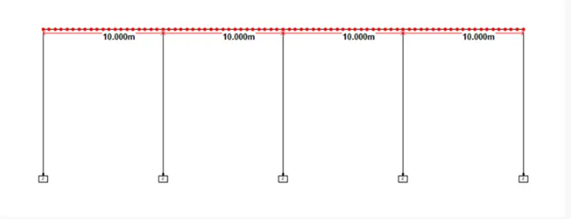
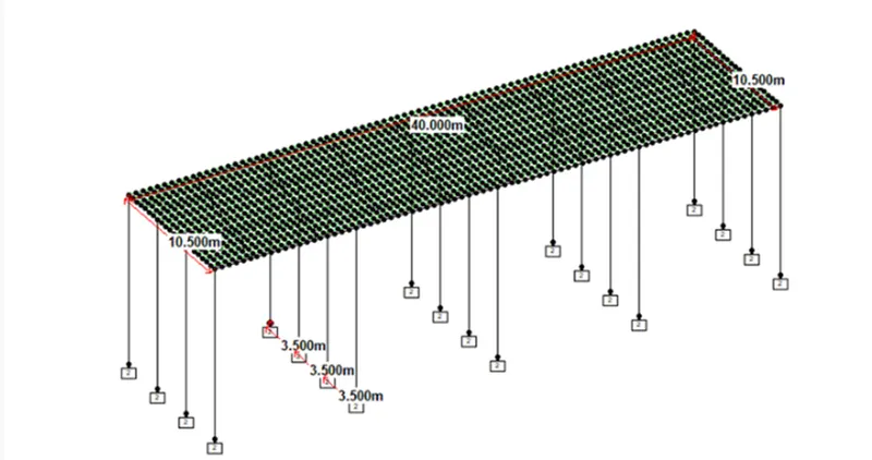
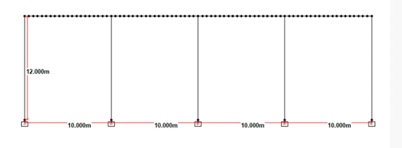
To calculate the water current forces, centrifugal forces, wave forces, snow loads, temperature loads, Barge Impact load for the bridge structure shown below
DATA GIVEN:-
Maximum Crest elevation for the wave = 3.0 m
Number of Main Girder = 4
Size of Main I Girder = Flange as 2.0 x 0.3m and Depth as 1.6 x 0.3m
Constant r = 5
Cva = 3
Storm Elevation = 8.5 m
Cr = 0.4
Highest Flood Level = 4 m above the Bottom of foundation
Span of bridge = 10.0 m
Mean velocity of river = 2.5 m/s
Width of carriage way = 9.0 m
Live load on Bridge = 70R Tracked vehicle
Radius of curvature (R) = 2.0 m
Design speed of vehicle = 50 km/hr
Size of Pier = 1.2 x 1.2 m
Width of deck slab = 10.5 m
Thickness of the deck slab = 1.5 m
Deck slab is flat.
Depth of snow = 1250 mm = 1.25 m
Dead Weight tonnage of Panamax vessel = 25000 Tons
No. of containers shipped by ship = 1500 containers
Each container = 6.1 TEU
ASSUMPTIONS:-
Depth of Foundation = 2.0 m
Speed of Barge vessel = 60 km/hr
Delhi
Coefficient of Thermal Expansion (α) = 12.0 x 10⁻⁶/ o C
Compressive strength of concrete = 40 N/mm2
Modelling of the Structure by Staad Pro. V8i
Modelling of structure is done as per given questions
Size of Cross beam = 1.0 m x 1.4 m
Hydrodynamic Coefficient (CH) = 1.25
Type of Snow = Damp New Snow
Location of bridge = New Delhi
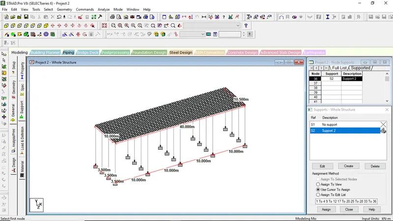
Property of the elements will be assigned as per given question
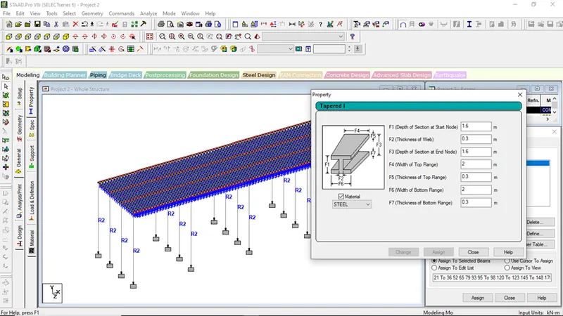
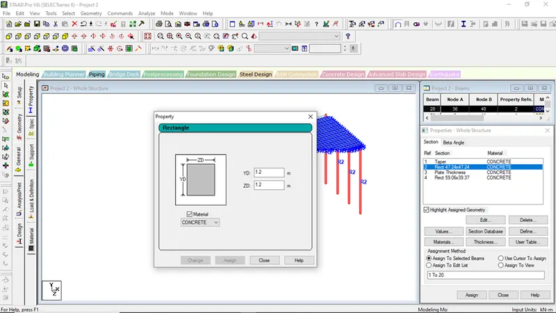
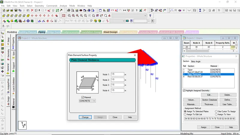
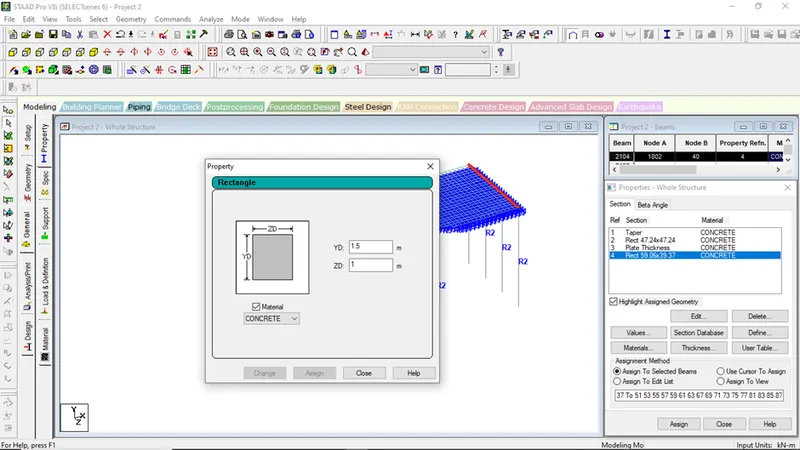
THEORY FOR WATER CURRENT LOADS:-
Water Current Loads:-
As per IRC 6:-2017, P=52KV2
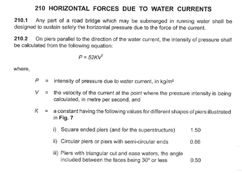
Calculations of water current loads
For Sqaure piers,
Shape factor K = 1.50
Height of H.F.L from foundation is 4m so water forces will be acting at 4m height of piers so,
Maximum Velocity, V = √2x Vmean
Mean Velocity = 2.5 m/sec (Given)
V= 3.53
Water Current Force, P = 52 x K X V2
= 52 x 1.50 x 3.53 x 3.53
P = 971.9 kN/m2
As Pier size is 1.2m x 1.2m, so final P = 1.2 X 971.9 = 11.66kN/m
Calculation of Centrifugal Loads:
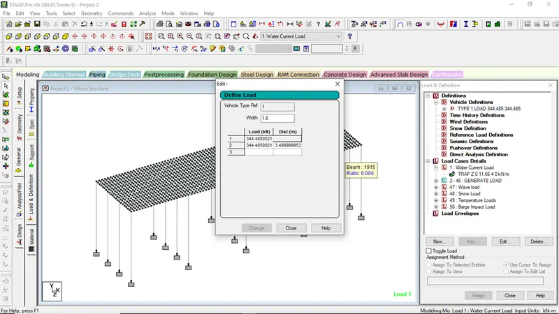
Live Load due to 70R Tracked vehicle (W) = 70KN
Design Speed of vehicles (V) = 50 km/hr
Radius of Curvature (R) = 2.0 m
Centrifugal Loads (Fc) = (W x V2)/(127 x R) = (70 x 502)/(127 x 2) = 688.98KN
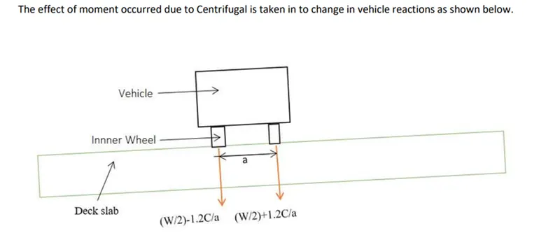
a= 1.8m
For Inner wheel
(W/2)-1.2C/a
= (70/2)-1.2*(688.97)/1.8
=-424.313
For Outer wheel
(W/2)+1.2C/a
= (70/2)-1.2*(688.97)/1.8
=494.313
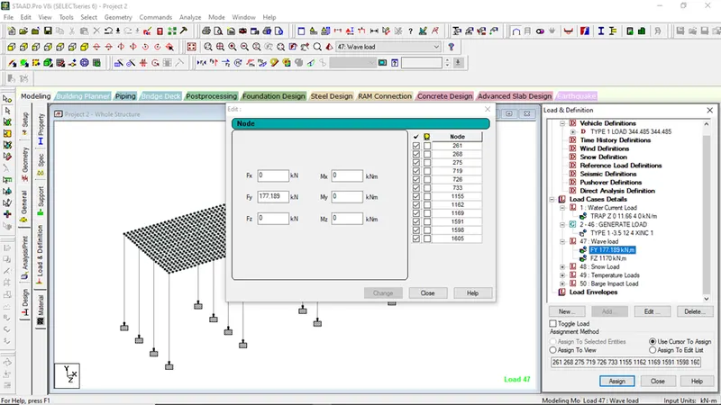
Calculation of Wave Loads:
Maximum elevation of wave crest, ηmax = 3.0 m
Depth of Superstructure = 1.5 m
ΔZh = ηmax – Centroid of superstructure = 3 – (1.5/2) = 2.25 m
ΔZv = ηmax – elevation of upside of deck = 3 – 1.5 = 1.5 m
Number of girders supporting bridge deck (N) = 4
Vertical load (Fv) = r x ΔZv x Av = 5 x 1.5 x (10.5 x (1.5/2)) = 59.063 KN
Horizontal load (Fh) = r x ΔZh x Ah = 5 x 2.25 x (10 x 1.5) = 168.75 KN
Maximum wave induced vertical load (Fvmax) = Cva x Fv = 3 x 59.063 = 177.189 KN
Maximum wave induced horizontal load (Fhmax) = (1+Cr x (N-1)) x Cva x Fh = (1 + 0.4 x (4-1)) x 3 x 177.189 = 1169.4474 KN
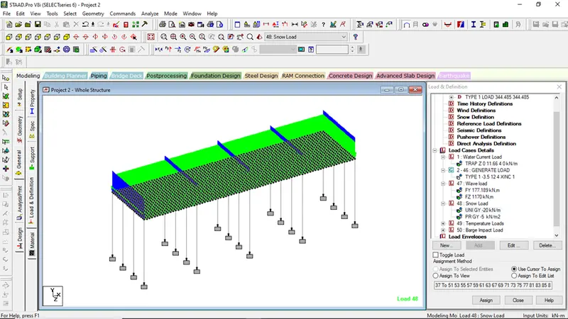
Calculation of Snow Loads:
Density of settled snow (ρ) = 200 Kg/m3
Depth of snow accumulation (D) = 1250 mm = 1.25 m
Slope of floor/roof (β) = 0
Snow Load, S0 = β x D x ρ = 2 x 1.25 x 10 = 25 KN/m
Shape Coefficient from IS 875 Part 4,
For angle β < 300, μ = 0.8
Design Snow Load,
S = μ x S0 = 0.8 x 25 = 20 KN/m
Calculation of Temperature Loads:
Maximum temperature at Delhi C.H.O. as per IRC 6 2017 = 47.8o C
Minimum temperature at Delhi C.H.O. as per IRC 6 2017 = -0.4o C
Effective temperature difference (Teff) = [(47.8 - (-0.4))/2] + 10 = 34.1 o C
Coefficient of Thermal Expansion (α) = 12.0 x 10⁻⁶/ o C
Young Modulus of concrete (E) as per IS 456 = 5000√fck = 5000 x √40 = 31622.777 KN/m2
Stress due to Temperature (σtemp) = α x Teff x E = 12.0 x 10-6 x 34.1 x 31622.777 = 12.94 KN/m2
Maximum Permissible Stress (σperm) = (2/3) x 0.7 x √fck = (2/3) x 0.7 x √40 = 2.952 KN/m2
So, Stress is reduced 3 KN/m2.
Positive Temperature Differences:
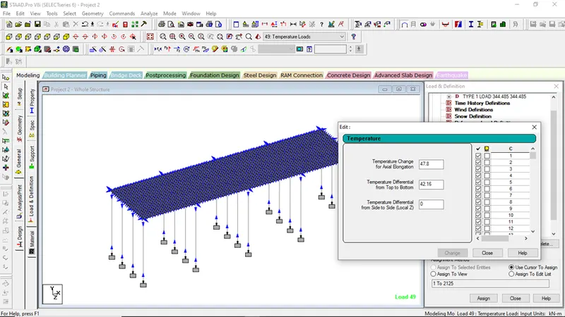
Temperature at top of deck = 47.8 o C
Temperature at bottom of deck = (2.1/17.8) x 47.8 o C = 5.64 o C
Reverse Temperature Differences:
Temperature at top of deck = 47.8 o C
Temperature at bottom of deck = (6.6/10.6) x 47.8 o C = 29.762 o C
Calculation of Barge Impact Loads:
Hydrodynamic Coefficient (CH) = 1.25
Barge Displacement Tonnage = 25000 DWT
Barge Impact Speed (V) = 60 km/hr. = 16.67 m/s
Barge Collision Energy (KE) = 500 x CH x W x V2 = 500 x 1.25 x 25000 x (16.67)2 = 260468750 N-m = 2.61 x 10⁸ N-m
Barge Damage Depth, aB = 3100 x ([1 + 1.3 x 10⁻⁷ KE]0.5 -1) = 3100 x ([1 + (1.3 x 10-7 x 2.61 x 108)]0.5 -1) = 15221.5 mm
Since aB > 100 mm
Then, Barge Collision Impact Force (PB)
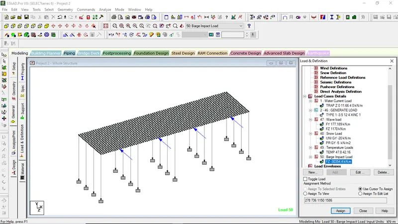
PB = 6.0 x 10⁶ + 1600 x aB = 6.0 x 10⁶ + 1600 x 15221.5 = 30354400 N = 30354.4 KN
PROCEDURES:-
STEP 1:-
Application of Loadings:-
- Water current loads
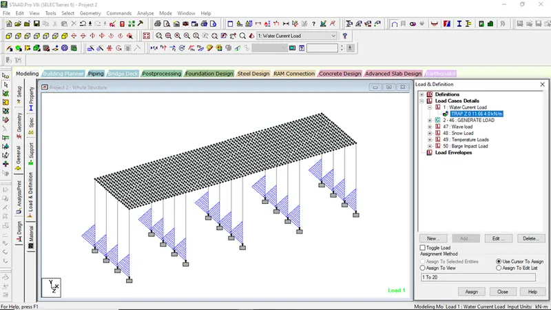
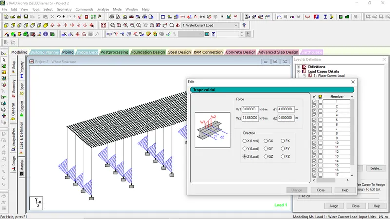
- Go to load and definition
- Select on load case details, click add
- Rename as water current load,click add
- Go to water current loads, select add
- Go to trapezoidal loadings, ;put the loading value as calculated above and assign it to the required structure
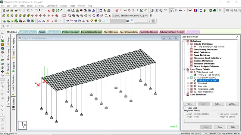
2. Application of Centrifugal Loads
- Go to Vehicle definations
- Select vehicle width = 1.8m
- Annotate the vehicle loads and the distance between the axle
- Go to Load case details, click add
- Go to load Generation
- of loads to be generated=45 (say)
- Assign vehicle start node
3. Application of wave loading to the structure
- Go to load cases details
- Select add
- Rename as wave loads
- Click on wave load, select add
- Go to nodal loads,
- Give the calculated load values in FY and FZ direction
4. Application of Snow loads to the structure
- Go to load cases details
- Rename as snow load
- Go to member loads, put the calculated value and assign to the cross girders of the structure
- Another Live load of 500kg/m3 was assigned to the deck slab of the structure
5. Application of Temperature Loads to the Structure
- Go to the load cases details
- Rename as temperature loads
- Select temperature loads
- Click add
- Go to temperature loads, click add
- Select temperature loads, put the calculated values in the given parameters
Then assign to view, Then OK
6. Application of Barge Impact Loads
- Go to Loads and Defination
- Rename as Barge Impact Loads, click add
- Select Barge Impact Loads, click add
- Go to Nodal loads
- Put the calculated load values and assign respectively
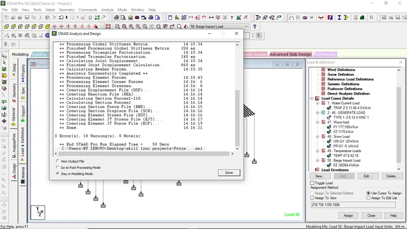
STEP 2:-
- Analyzing the model
- Go to Analysis and Print
- Select on no print option
- Go to Analyze menu
Select run analysis
Step 3:-
Go to post processing mode to get the final desired analytical results
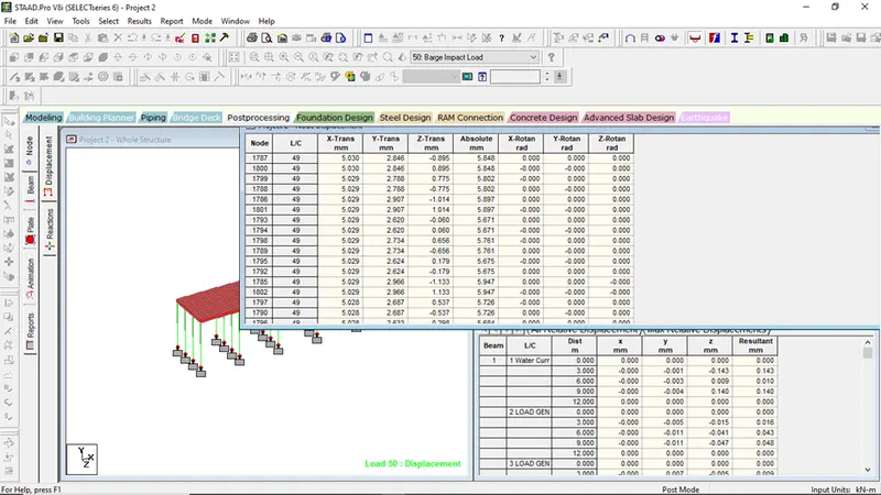
Figure showing values of joint displacement
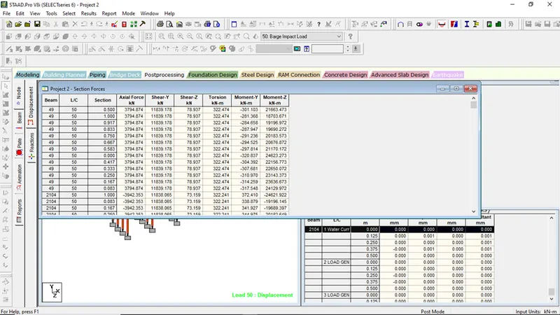
Figure showing maximum section forces on the bridge structure model
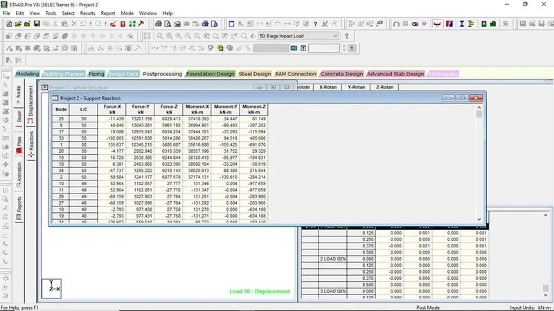
Figure showing the values of maximum support reaction acting on the bridge model
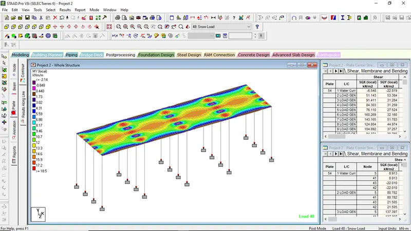
Figure showing plate contours on action of snow loading on MY local