Project 2
DESIGN AND ANALYSIS OF BRIDGE WITH WATER CURRENT LOAD,CENTRIFUGAL LOAD,WAVE LOAD,SNOW LOAD,TEMPERATURE LOAD AND BARGE LOAD
AIM
To Design and analyse a bridge with Water current load,Centrifugal load,wave load,snow load,temperature load and barge load using STAAD Pro. Software.
INTRODUCTION
As per the given data and standard formulas the water current load is being calculated manually.
Max. velocity = √2 x Vmean
= √2 x 2.5 = 3.53 m/s
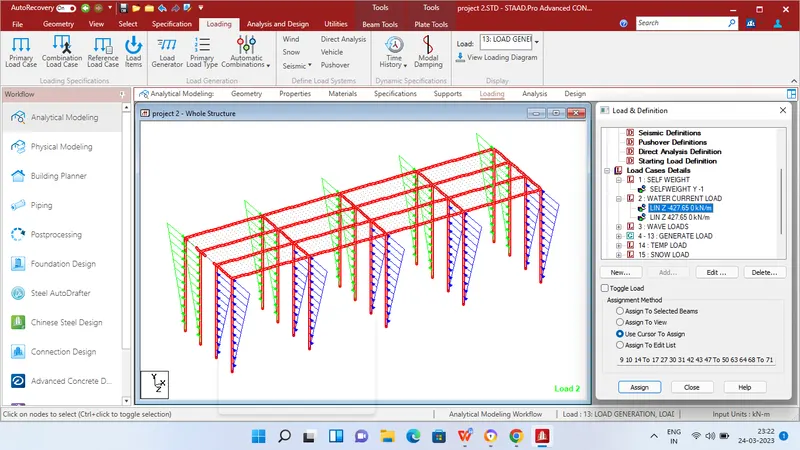
Water current ,P = 52 KV^2
= 52 x 0.66 x 3.53x 3.53
= 427.65 KN/m2
As per the given data and standard formulas the centrifugal load is being calculated manually.
As given in question Live load is 70 KN for 70 R tracked vehicle
so,Centrifugal force = WV^2/127 R
= 70 x 50^2/127 x 3
= 689 KN
As per the given data and standard formulas the Wave load is being calculated manually.
η max = 3
Δ zh = 3 - (1.6/2)
= 2.2 m
Δ zv = η max - Elevation of bottom deck
= 3 - 1 = 2
Number of girders N = 4
F v = r x Δ zv x A v
= 5 x 2 x (9 x 1.6/2)
= 90 x 1.6/2
= 72 KN
F vmax = Cva x Fv
= 3 x 72 = 216 KN
F hmax = 1+Cr(N-1) x Cva + Fh = 581 KN
As per the given data with standard formulas as per IS 875 Part 4 the Snow load is being calculated manually.
Density of snow = 2 KN/m3
So = Density of snow x depth of snow accumulation x span of bridge
= 2 x 1.25 x 10 = 25 KN/m
μ = 0.8 (Shape coefficient as per IS 875 Part 4)
S = μ x So
= 0.8 x 25 = 20 KN/m
As per the given data with standard formulas as per IRC 6 the temperature load is being calculated manually.
As the bridge has to be designed in Delhi the Maximum and Minimum temperature as per IRC 6 Isotherm is
Maximum Temperature = 47.5 °C
Minimum Temperature = -2.5 °C
Effective temperature difference = (47.5 - (-2.5))/2 + 10
= 35 °C
Stress due to temperature = α x ΔT x E
= 11.27 x 10^-6 x 35 x 5000√fck
= 11.27 x 10^-6 x 35 x 5000√40
= 12.47 KN
Maximum permissible stress = 2/3 x 0.7 x √40
= 2.95 KN/m2
Differential temperature top to bottom = 41.9 °C
As per the given data with standard formulas the Barge load due to Panamax is being calculated manually.
KE = 500 x CH x W x V2
= 500 x 1.25 x 25000 x 16.6 x 16.6
= 4.3 x 10^9
Barge damage depth
aB = 3100 X ((1+1.3 x 10^-7 x 4.3 x 10^9)^0.5)-1
= 70260 mm
If aB is greater than 100mm
PB = 6 x 10^6 + 1600 x aB
= 118320 KN
PROCEDURE
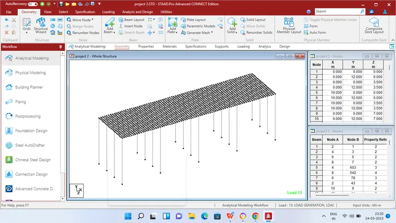
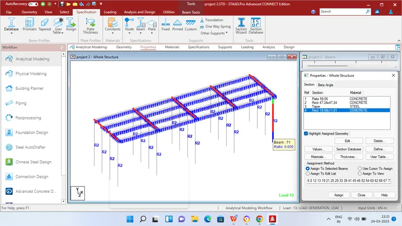
Step 1 - Create Nodes by entering the corresponding X/Y/Z values in the Node table for Creation of geometry for Truss bridge structure with elements such as Piers,Beams,Deck slab etc.,
Step 2 - After creating the nodes connect those nodes with add beam option.
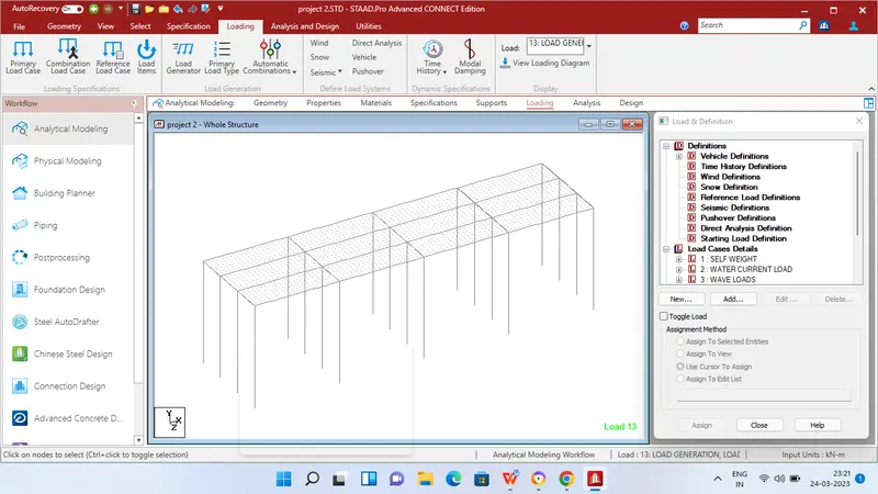
Step 3 - Then Click specification tab and click fixed support tab
Step 4 - After that in create support dialog box add fixed support for all the piers in the geometry using assign for selected nodes option.
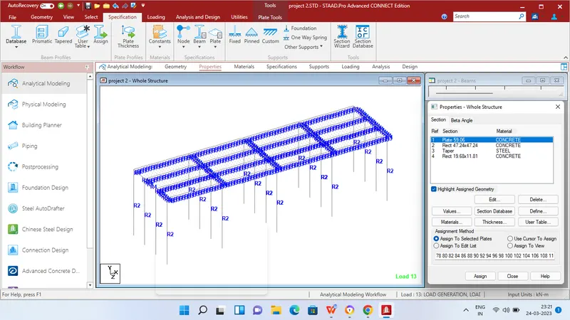
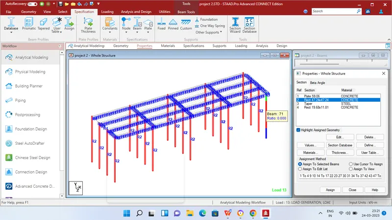
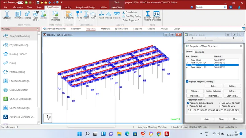
Step 5 - Then in Properties tab click Prismatic and add the Rectangle sections for beams - 0.5 x 0.3 m,1.2 m x 1.2 m Piers,I girder with height 1.6m Top and bottom flange width 2m Thickness of web 0.3mand respective thickness for plates 1.5m as given in the question data
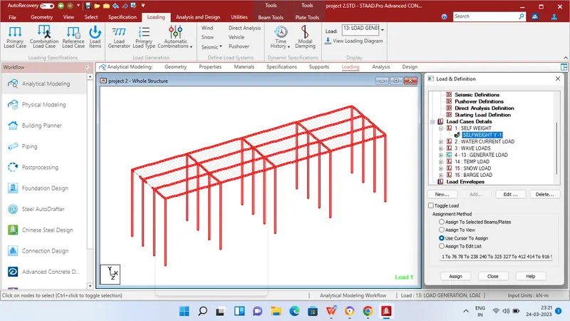
Step 6 - After adding the properties click Loading tab and add load cases for Self weight,water current load
Step 7 - Then apply self weight to the entire geometry.
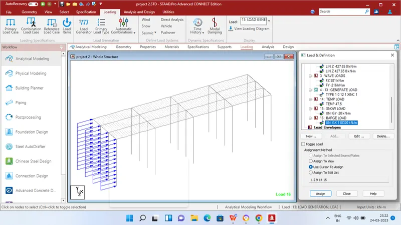
Step 8 - After applying the self weight add Live member load - Linearly varying load of 427.65 KN as per manual calculation to the Piers of the bridge for full length of the pier
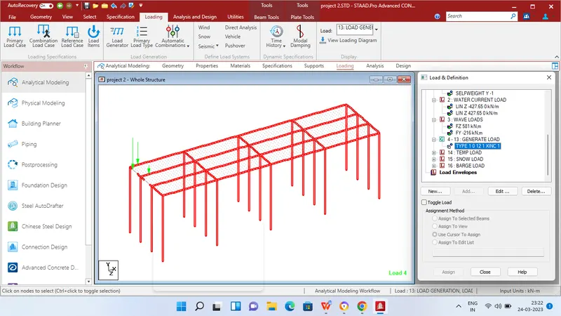
Step 9 - After that define vehicle definition add 689 KN as axle load and distance of 1.5 m b/w axles.
Step 10 - Then apply Load generation for required no of loads click add and then find out the initial position of vehicle by using select node option and enter the corresponding x,y,z values also enter increment value.
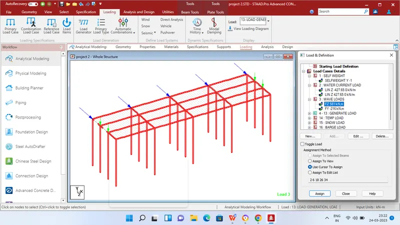
Step 11 - Then add Wave load under Load cases.
Step 12 - Then apply Nodal load of the calculated values of Maximum horizontal load = 581 KN at Z direction and Maximum vertical load of 216 KN at Y direction.
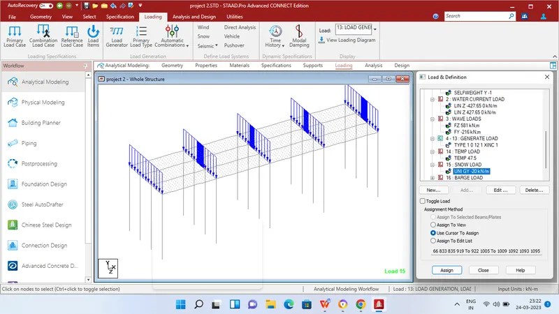
Step 13 - After that click Loading tab and add Snow load under Load cases.
Step 14 - Then apply Uniforce member load of the calculated value = 20 KN/m and Minimum snow load as per IRC 9 KN/m plate load.
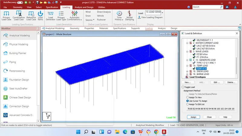
Step 15 - After that click Loading tab and add Temperature load under Load cases.
Step 16 - Then apply Temperature load of Differential temperature from Top to bottom the calculated value = 41.9 °C
Step 17 - Then click Loading tab and add Barge load under Load cases.
Step 18 - Then apply uniform member load at Global Z axis as 118320 KN as calculated above.
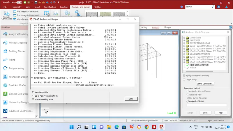
step 19 - Then in Analysis and design tab define commands for PERFORM ANALYSIS and click run analysis.
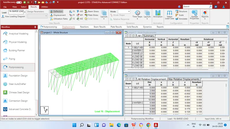
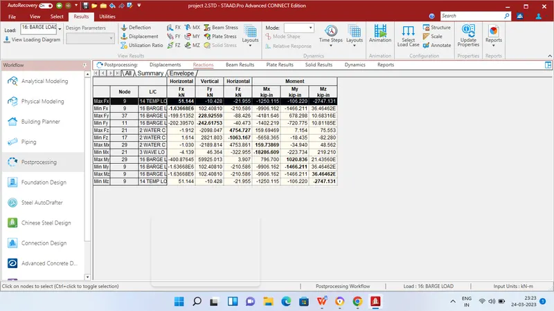
RESULT