Project 2
1.AIM :-
Here we calculate the forces due to water current forces ,centrifugal forces, wave forces, snow loads, temperature loads and Barge Impact load on a bridge.
2.INTRODUCTION:-
Here we have a bridge of 4 span bridge where each span is 10 m and width is 10.5 m . here we apply the forces due to water current force, centrifugal force, wave force , snow load , temp load as well as barge ipact load on brige. As per requirments here some data are given and another data shall be calculated or define with the help of IS code and find out the desire results which will help de desing a bridge.
3. GIVEN DATA :-
1.bridge length -40m
2.span - 10m
3.width- 10.5m
4.carriage way width -9m
5.thickness of slab -1.5m
6.type of girder -I
7.height -1.6m
8.top/bottom flange -2m
10.web/flange thickness -0.5m
11.span -04
12.pier -rectangular
13.diamension-1.2X1.2m
14.height-12m
15.transverse spacing -3.5m
16.max crest elevation for the wave -3m
17.constant(`gamma`)=5
18.Cva-3
19.strom elevation -8.5m
20.Cr-0.4
21.HFL from bottom of foundation -4m
22.mean velocity of river -2.5m/s
23.live load -70R tracked vehicle
24.radious of curvature -2m
25.design speed of vehicle -50kmph
26.B<20
27.depth of accumulation of snow-1250mm
28.dead weight of tonnage of panamax vessel- 25000DWT
29.capacity -1500 containers
30.1container-6.1 TEU.
here these data are given so from these data we calculate the required load/forces on bridge . as required some data will be assume as per requirments.
4.PROCEDURE :-
1.Water current forces:-
a forces produce due to water current on a brige is known as water current forces. the effect due to water current forces here we calculate as per IRC 112-2020,
P=52KV^2
Here ,
P=water current forces,
K=constant for pier shape , here pier are rectangular spape so k=1.5
V=Max velocity of water current
=2^0.5*Vmean
so,
P=52*1.5*((2)^0.5)*2.5
=275.730 kn/m2
here pier width is 1.2m ,if we calculate the intensity of force for load in unit width of pier
=275.730/1.2
=229.775kn/m in intensity max to zero for base .
2.Centrifugal forces:-
when a vehicle moving in a curve ,vehicle produce an outward pushing force on bridge/structure ,this force called as centrifugal force .
the force due to centrifugal force on structure can be calculated as per IRC -112-2020.
C=WV^2/127R
here ,
C=Centrifugal force ,
W=live load
V=Design speed of vehicle
R=radious of curvature
so,
C=70*50*50/127*2
=688.976kn
=689kn/m.
3.Wave forces:-
According to IS 4651 code ,waves are caused by disturbance of the water surface.
wave induced varying loads are calculated in terms of vertical and horizontal loadts.
here ,
(Fv)max=Cva-vXFv*
here,
Cva-v=imperical cofficient for vertical varying load.
Fv*=(Gama)(DeltaZv)XAv
here ,
Gama=unit weight of water
delta Zv=Differance between elevatin of crest of max wave and elevation of under side of bridge deck .
Av=Area of bridge contributing to vertical uplift.
put the values ,
Gama=5kn/m3
Delta Zv=Max crest elevation - height of girder
=3-1.6
=1.4
Av=width of slab X unit length of bridge
=10.5X1
=10.5m2
so,
Fv*=5*1.4*10.5
=73.5 kn
for ,
(Fv)max=3*73.5
=220.5kn
=221 kn .
(Fh)max=[1+Cr(N-1)]Cva-hXFh*
here ,
Cr=reduction cofficient for reduced horizontal load on the interval girder
N=no of girder
Cva-h=emperical co efficient
Fh*=gamaXDeltaZhXAz
here ,
DeltaZh=max crest elevation -cg of girder
=3-(1.6)/2
=2.2m
Az=Area of slab for apply the load
=10X1m2
=10m2
Fh*=5*2.2*10
=110kn
so,
(Fh)max=[1+0.4(4-1)]*3*110
=(2.2)*330
=726Kn
Now apply the load on bridge with the help of staad pro.
4.Snow load :-
According to IS code 875 Part IV , bridge structures are subjected to snow load when the bridge is located in snowy resion .snow are calculated as per IS 875 part IV and loads are applied accordance with IRC -06.
here some data are given and remaining data shall be calculated withing the range of IS code .
Minimum snow load =900 kg/m3
so,
design snow load 9s)=mu X So
here ,
mu=shape coefficient
=0.8
So=snow load on ground
=density of snow X depth of snow X span of bridge
=9X1.250X10
=112.5 kn/m
so S=0.8X112.5
=90kn/m
So,
calculated snow load apply on bridge with the help of staad pro .
5.Temperature load :-
According to IS code 875 part V ,the effect due to differance in temperature the load create on brige calculate and apply with the help of staad pro with the use of given calculation .
Here let we assume that the temp differance are such as
Max = 20
Min =-10
Grade of concrete =M40
so,
Delta T = (20-(-10))/2
=15
add 10 due to avg value is less than 20 degree
so delta T =15+10
=25
Now stress due to temp
= Alfa X delta T X coefficient of temp
=11.27X10^-6X25X5000(40)^0.5
=8.909 kn/m3
But max permissible stress due to temp = 2/3X0.7Xfck
=2/3*0.7*(40)^0.5
=2.951
=3 kn/m2
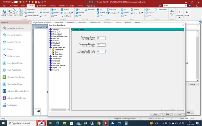
temp at top =20
temp at bottom of slab =(2.1/17.8)X20
=2.395
differance of temp at top and bottom of slab
=20-2.395
=17.605
with the help of staad pro we apply the temp effect load on the bridge model and get the results
6.Barge Impact load:-
According to IRC -112 we calculate the barge impact load on bridge
Here ,
Ke=500 X Ch X W X V^2
Here ,
V= 60 km/hr
W= 25000 DWT
Ch= 1.25 (Assumed)
so,
=500X1.25X25000X60X60
=56250X10^6 (N-M)
Barge damage depth ,
AlfaB=3100[(1+1.3x10^-7XKe)^0.5-1]
=262008.911mm
Here AlfaB>=100mm ,
so
Barge collision impact force ,
Pb=6X10^6+1600XAlfaB
=419214.893 kn
uniform force at slab of Bridge ,
Pb/length of bridge
=419.215X10^3/10
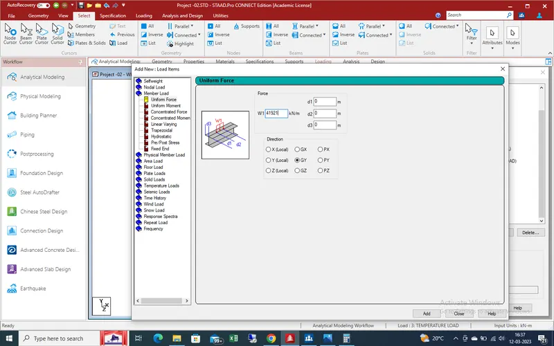
=41921.489 kn/mm.
We calculate all required all load which need to check in given bridge so we create the model in staad and apply the calculated load and find the results
Procedure :-
Now the help of staad pro we calculate the desired value of bridge for it we open an new window in staad as showing given pic as below
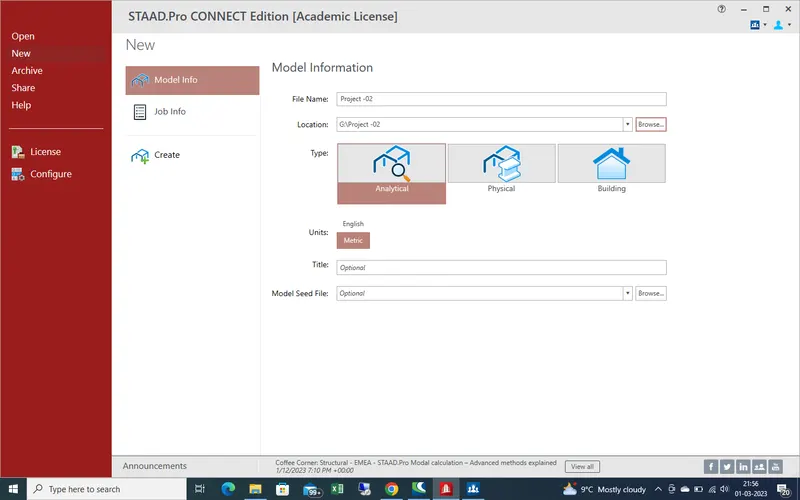
as new project name as project-02 and start the modeling with the help of 0,0,0 node as starting node
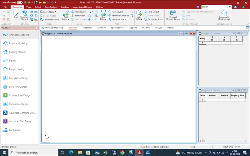
Here height of pier is 12 so create second node at 12m distance in Y-direction
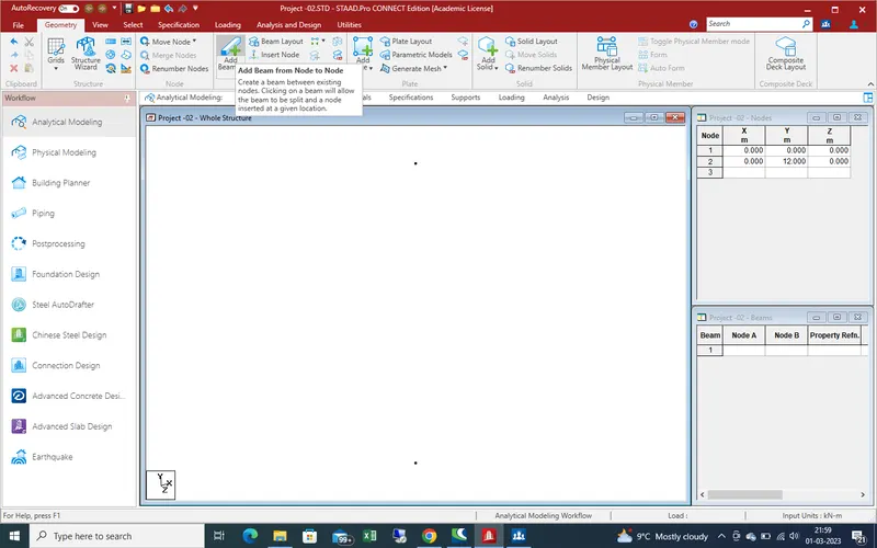
With the help of "add beam " command creat the pier for bridge
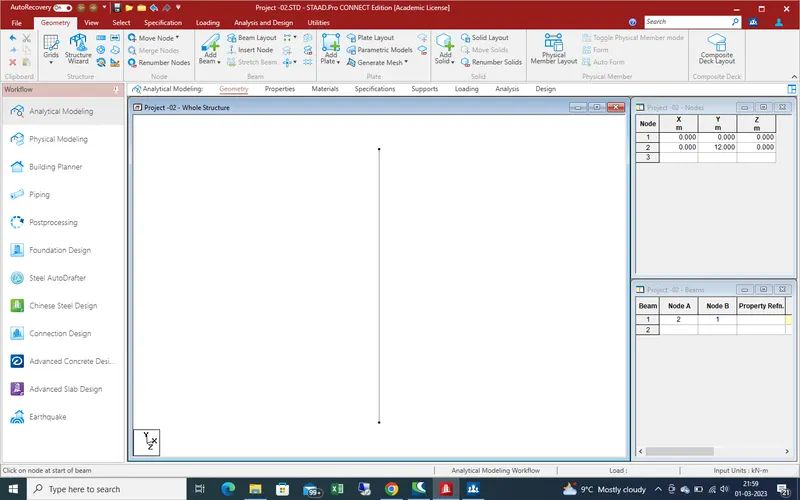
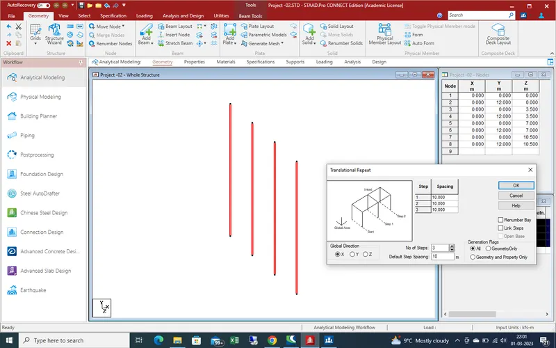
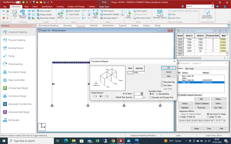
With the help of translation repeat command we create the all pier as showing in given pic
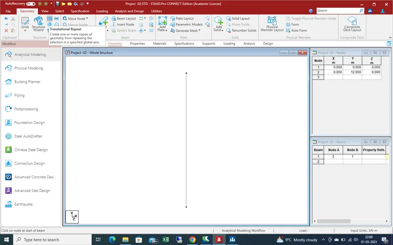
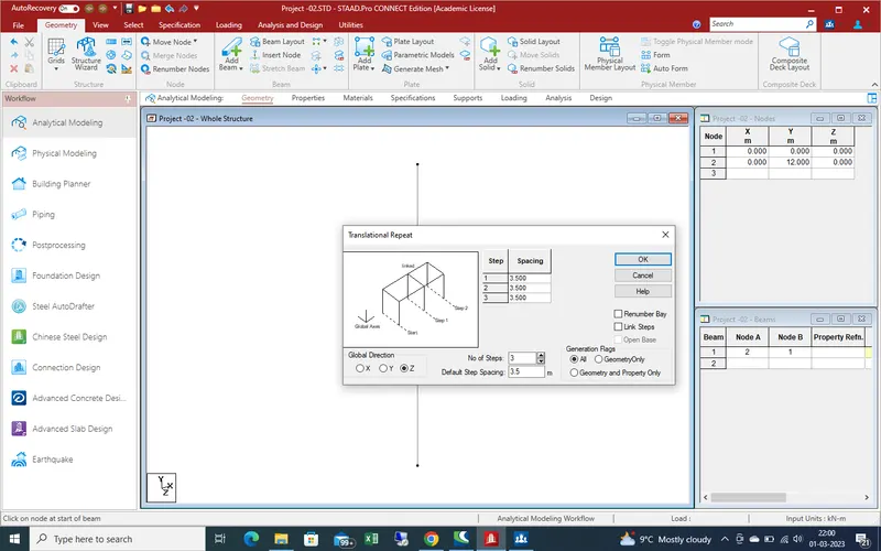
Here spacing between piers are 3.5 m so put the spacing values and no of pier are 4 so put the value of no of steps in Z-Direction
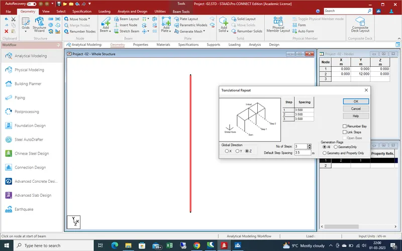
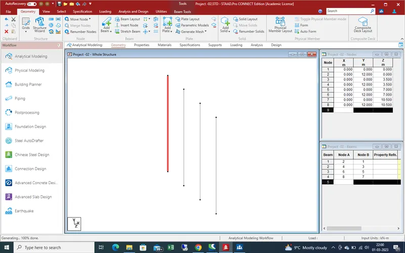
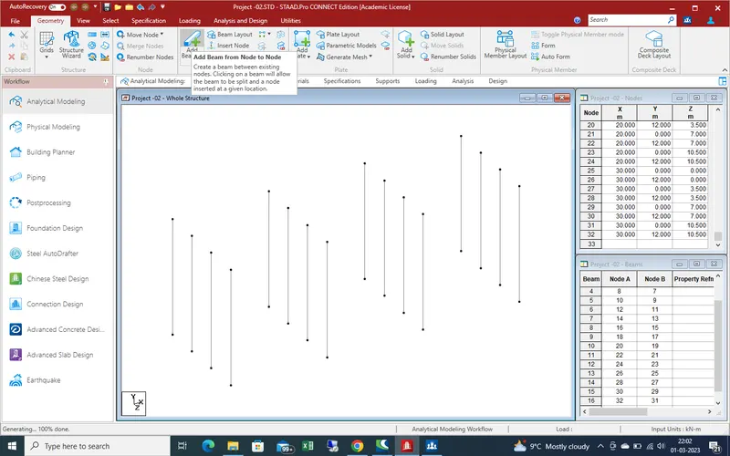
Again select the all pier which are created in Z-direction now here 3 nos of span so with the help of translation repeat command create the pier
Get the results as showing in given pic
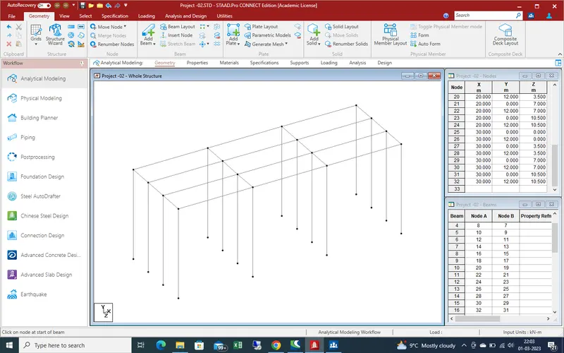
With the help of add beam command create the main girder and cross girder as showing in given below pic .
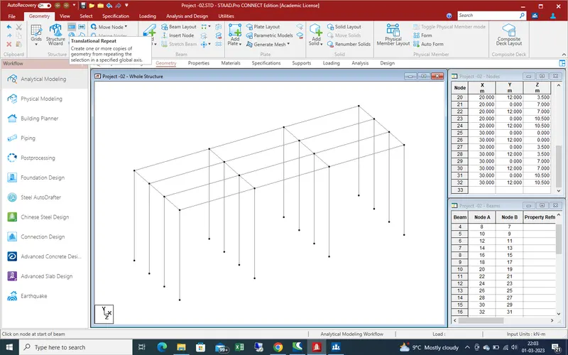
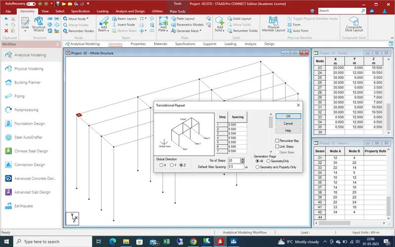
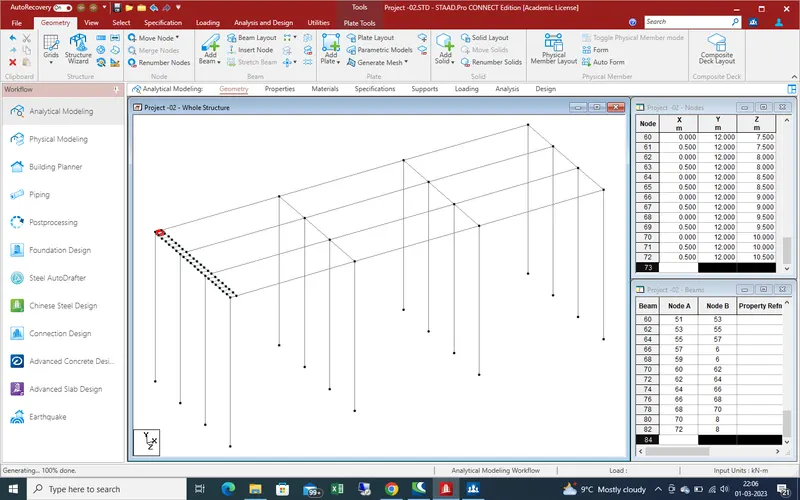
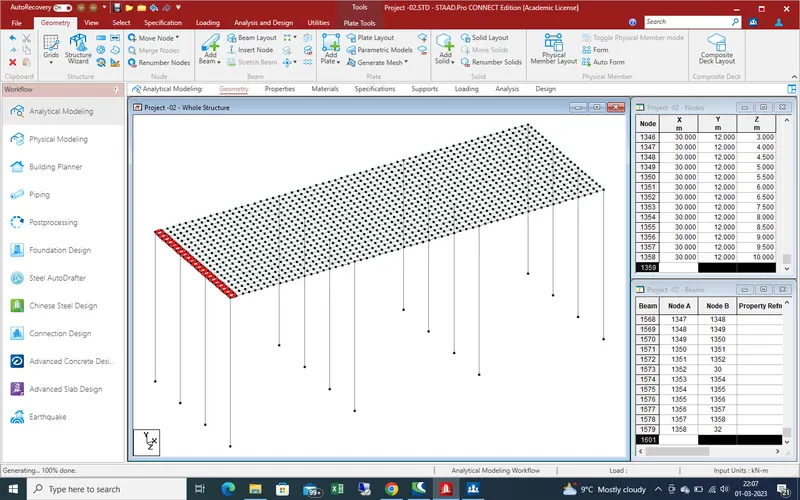
Now create the plate, so agian required 4 nodes for plate ,we create the nodes at 0.500 m spacing with the help of translation repteat command
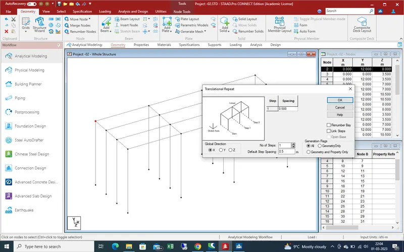
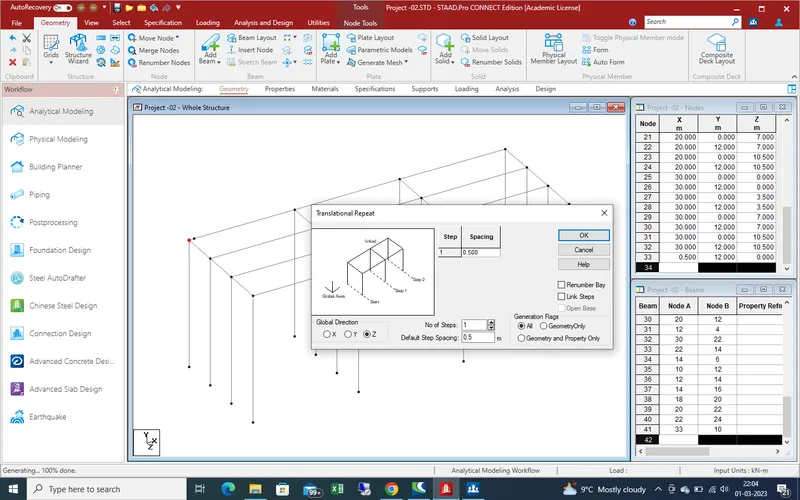
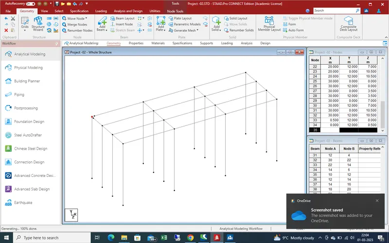
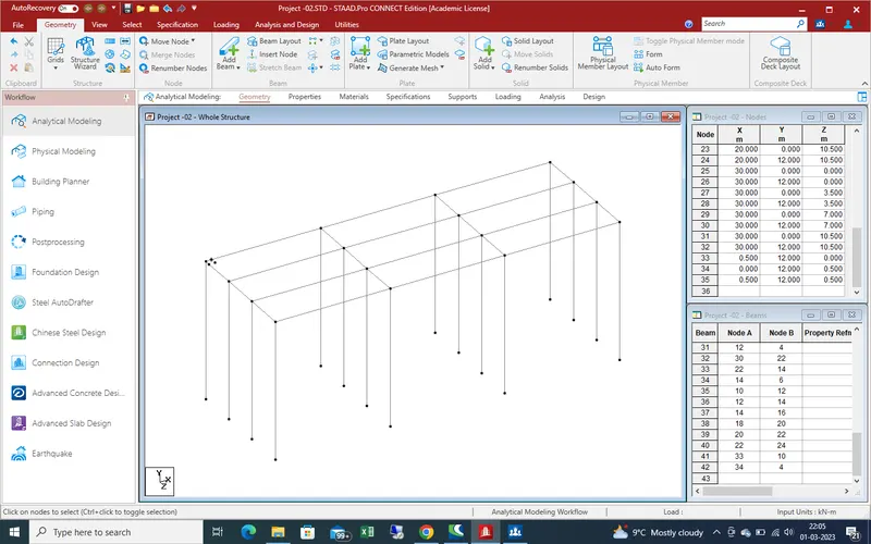
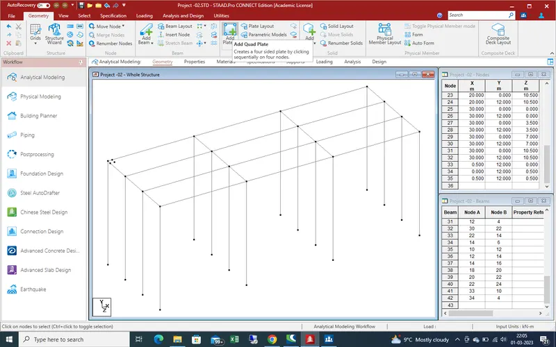
create the plate in Z-direction with the help of translation repeat command as showing in given pic .
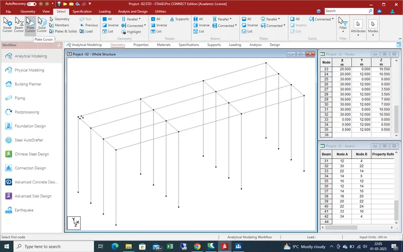
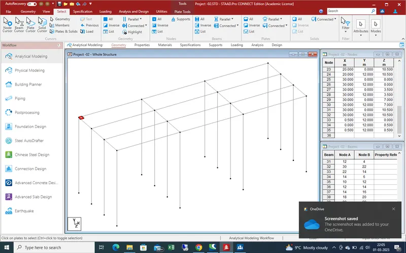
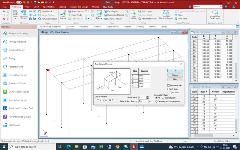
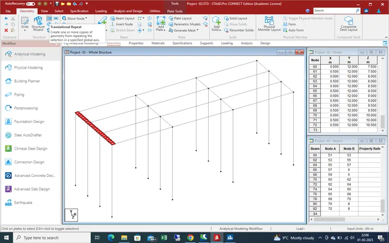
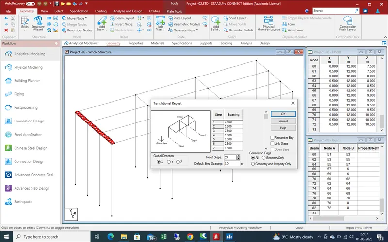
Now select the plate and create the plates in X-direction with the help of dranlation repeat command .
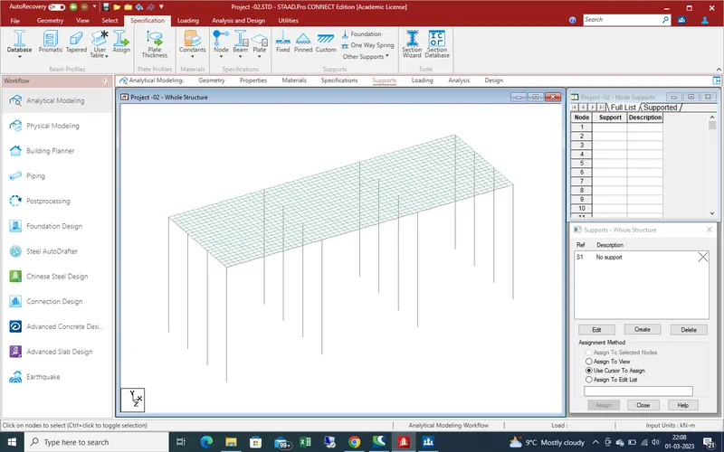
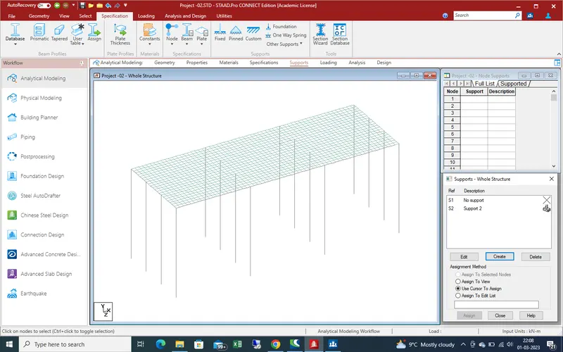
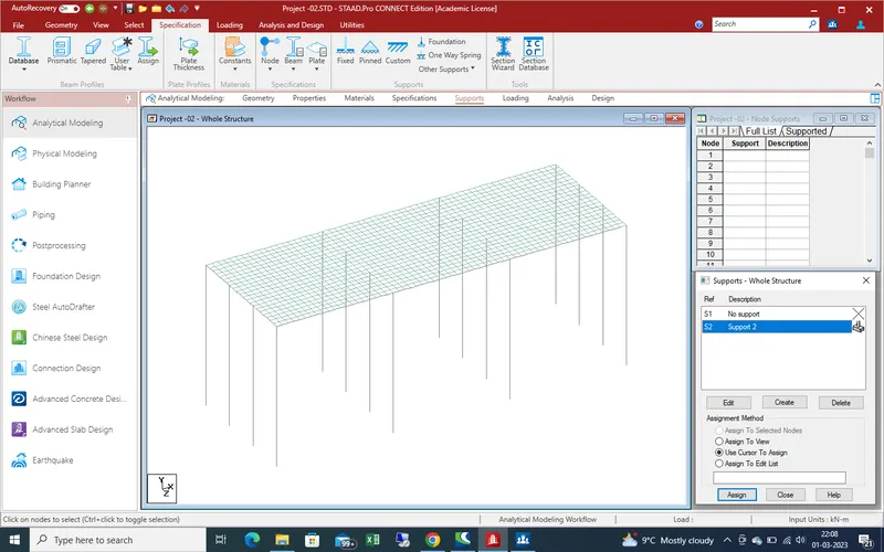
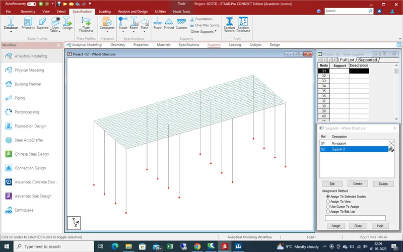
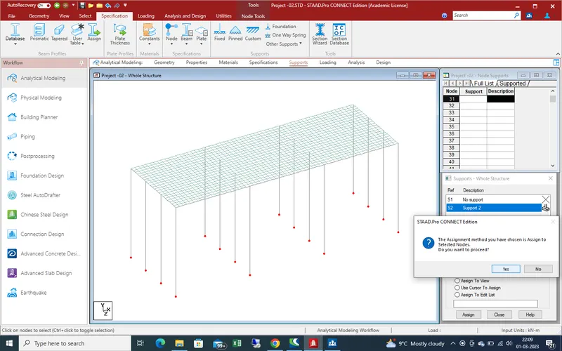
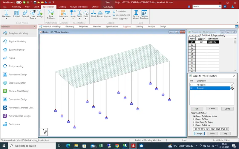
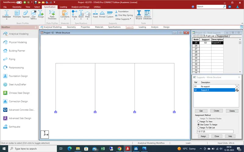
Now create support at end of bridge as here we assume that the support are fixed support as assign the fixed support and apply as shown in given below pic .
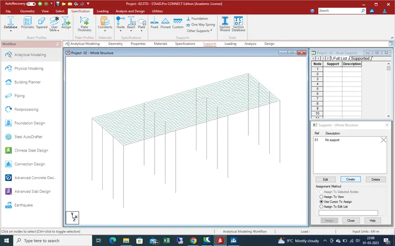
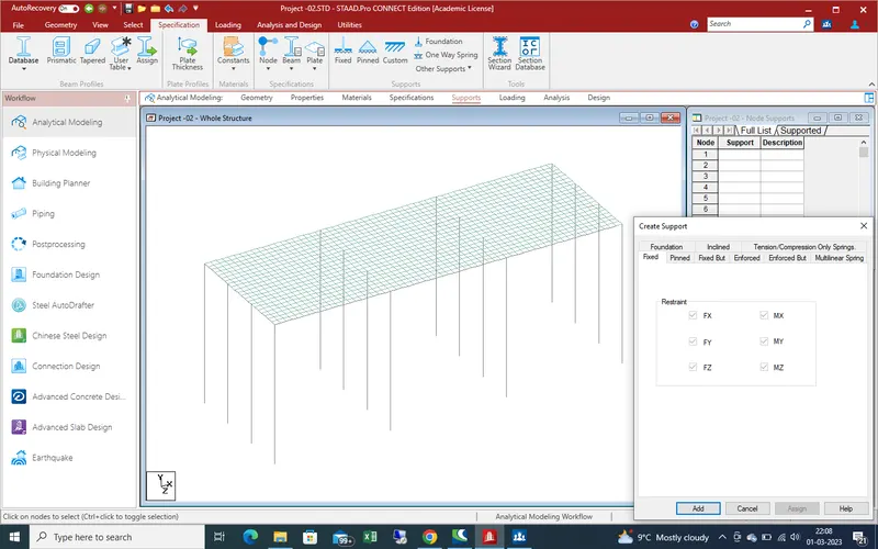
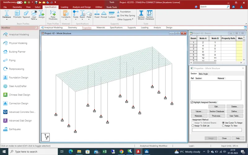
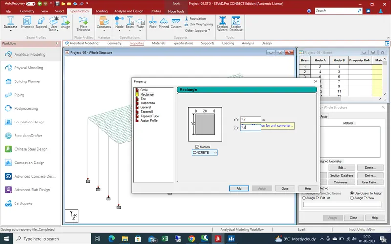
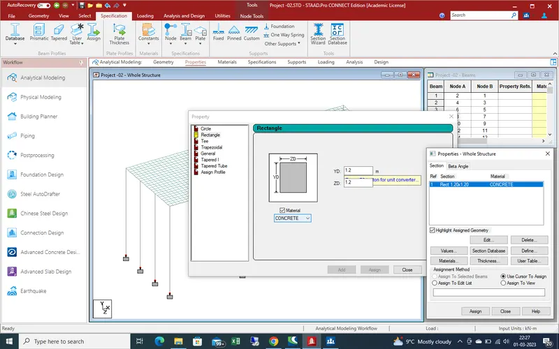
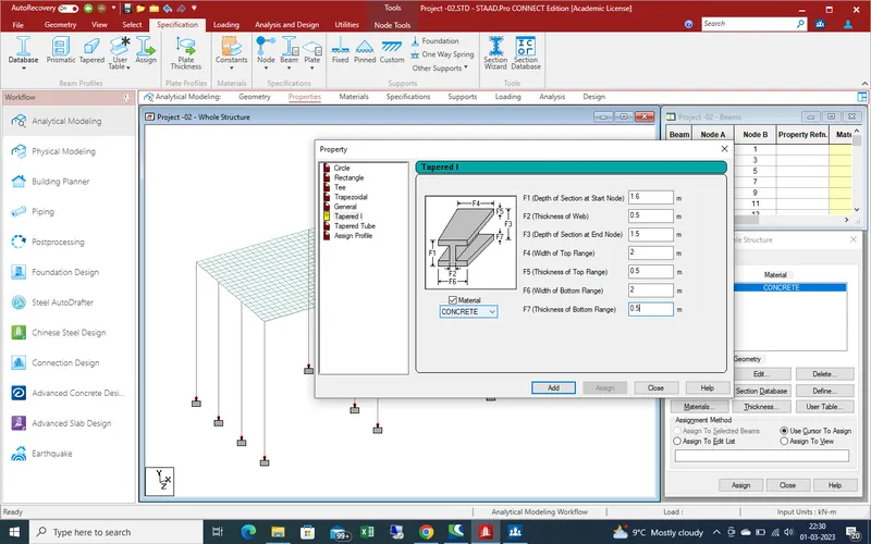
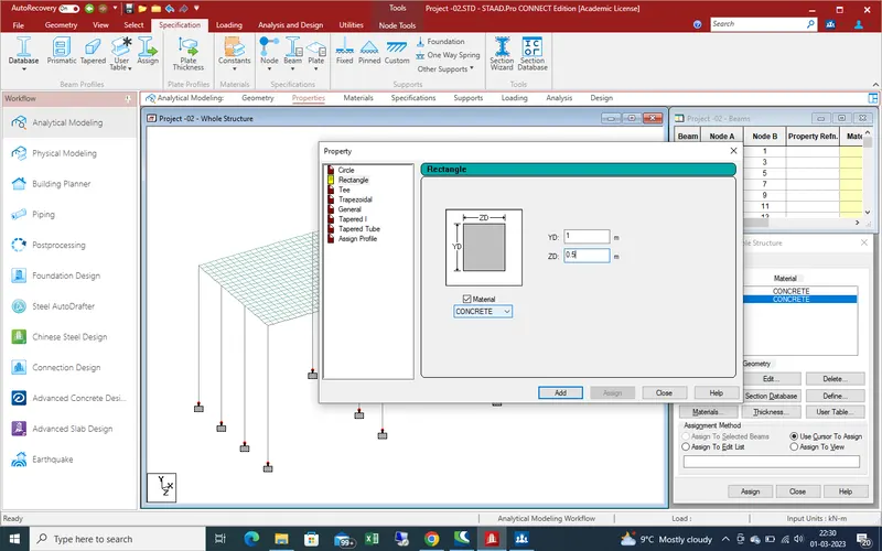
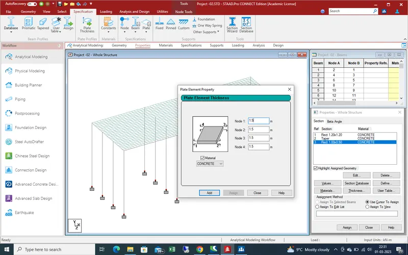
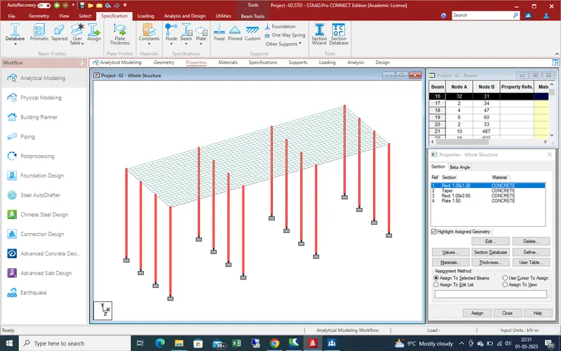
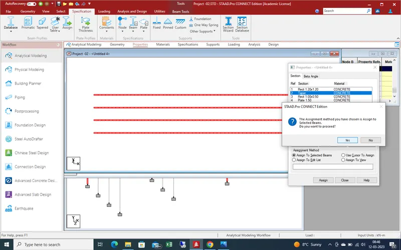
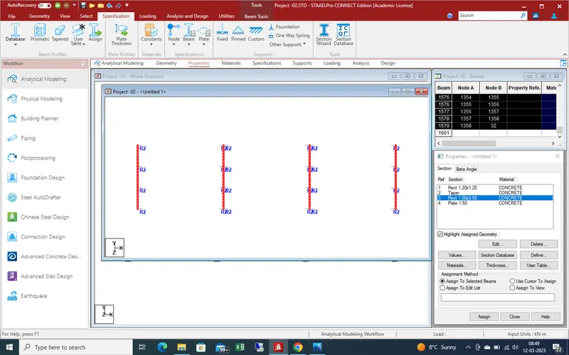
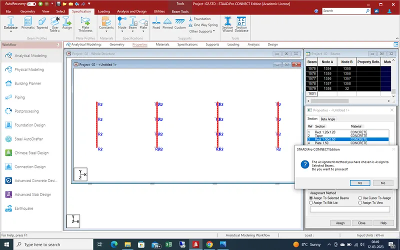
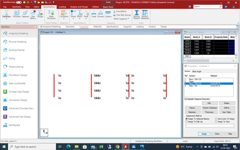
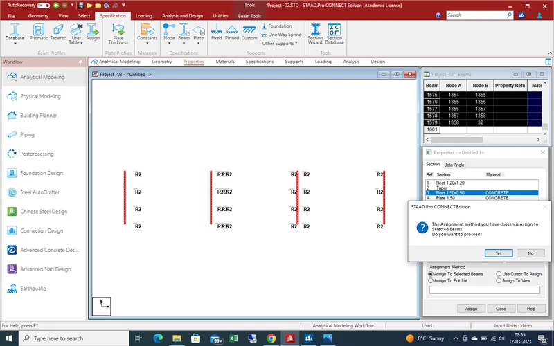
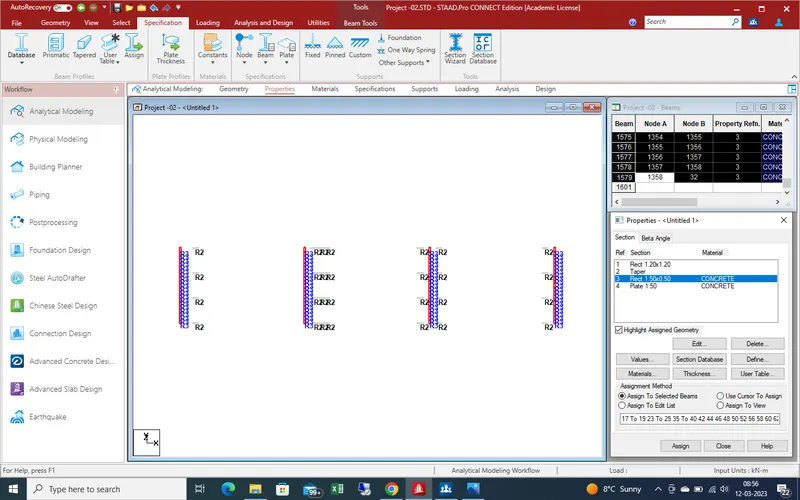
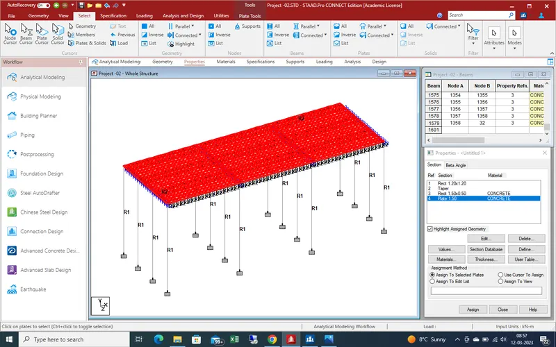
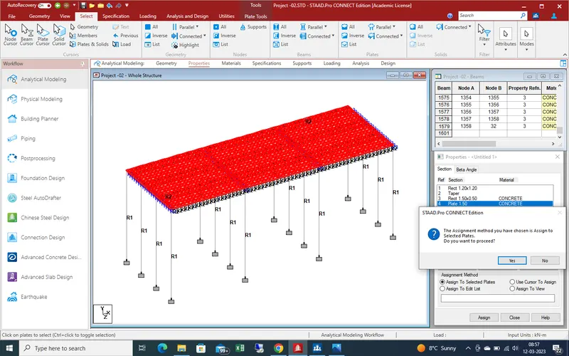
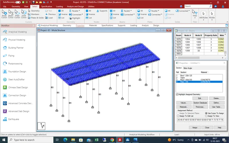
Now create the properties and assingn as details are given as detailed
Now we define the loading and apply as shown in given
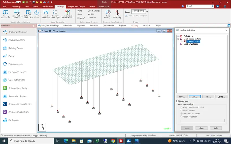
as here we calculate the wave load. Go the Load case and add new
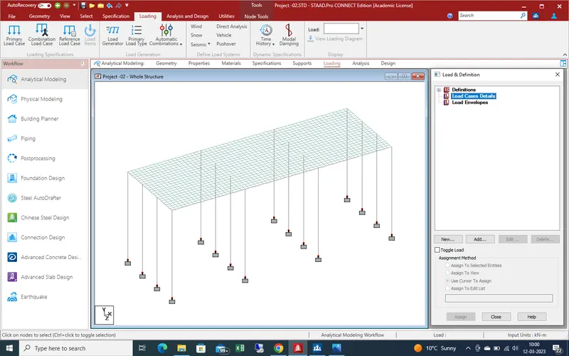
Give the name as wave load and add it after that add a new window will open as showing in given below pic
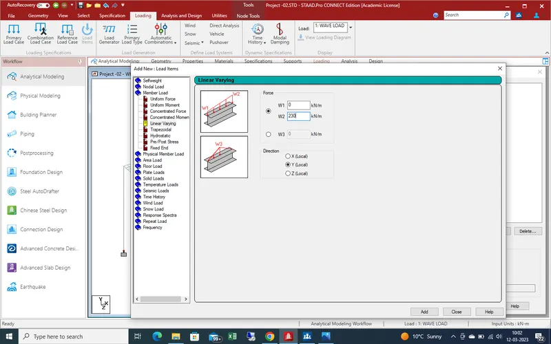
In new window go to linear varying force a new side window open as showing . Select the direction load as y- direction and load intensity as above calculated is 230 kn/m
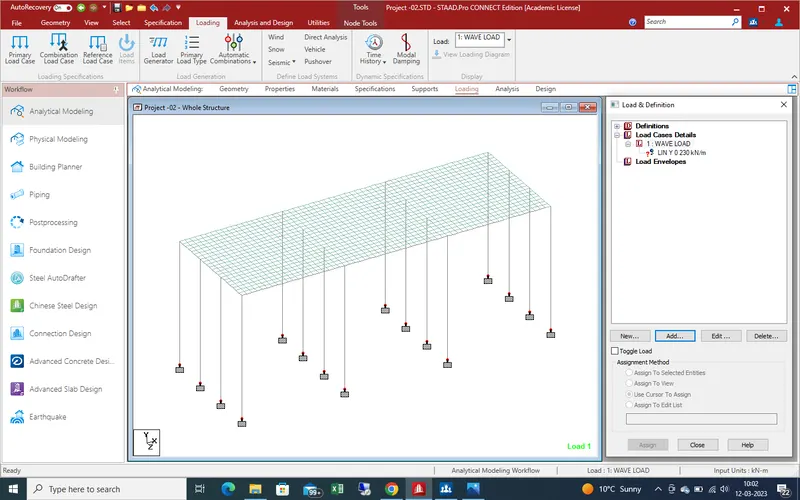
After load define assign the loading on pier as specified location as showing in given below pic.
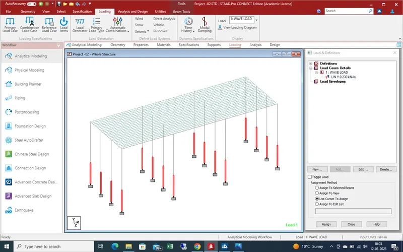
Assign the load as shown given pic .
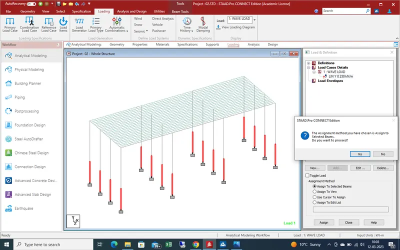
Get the results as
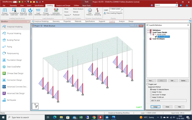
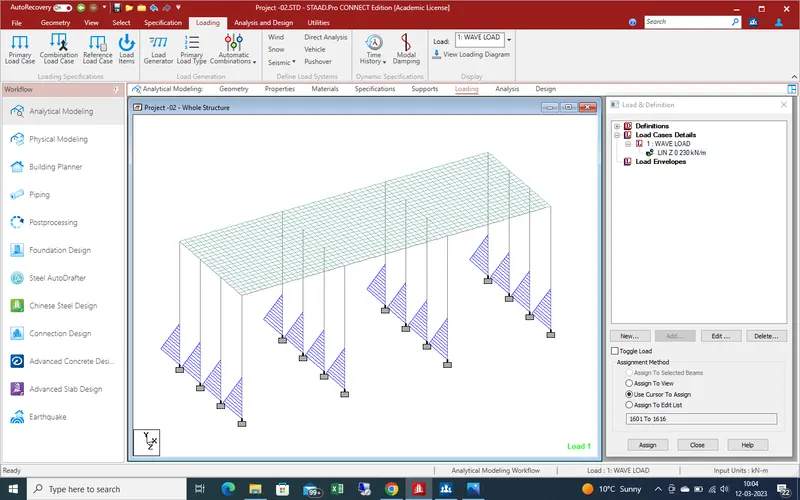
Now go for centrifugal force on bridge which is based on moving load as shown as given pic .
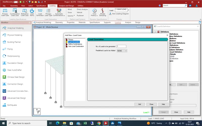
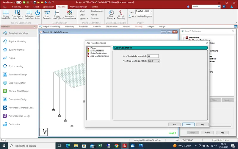
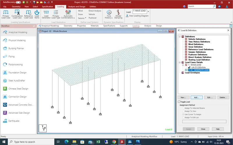
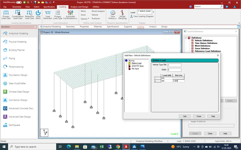
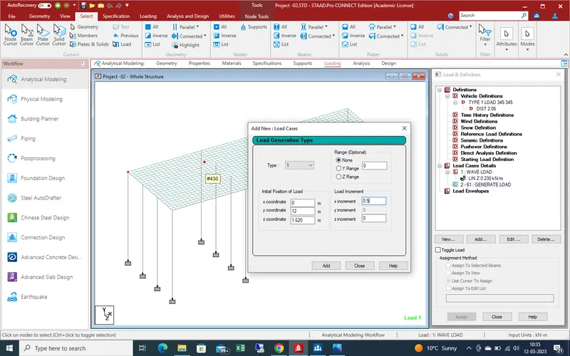
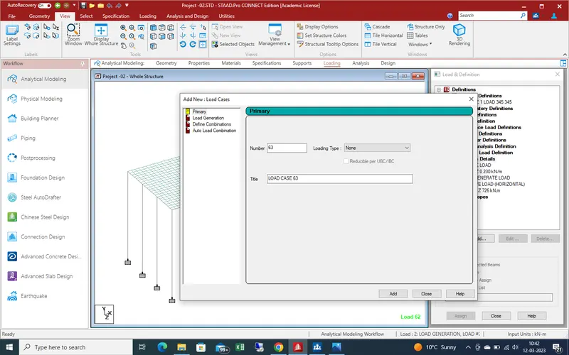
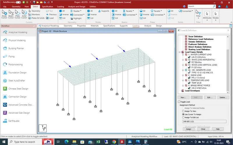
Now define the wave load on bridge as shown in given below pic .
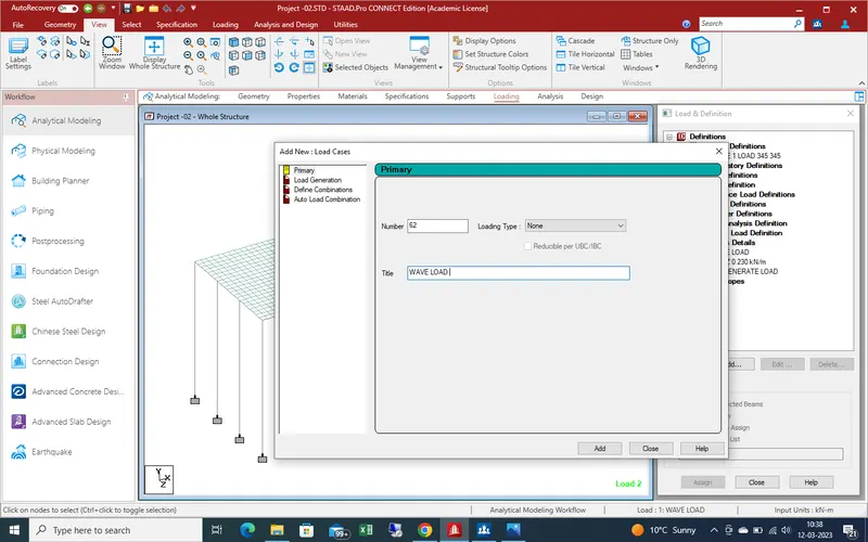
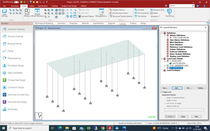
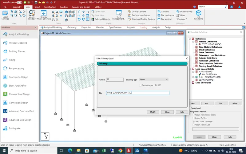
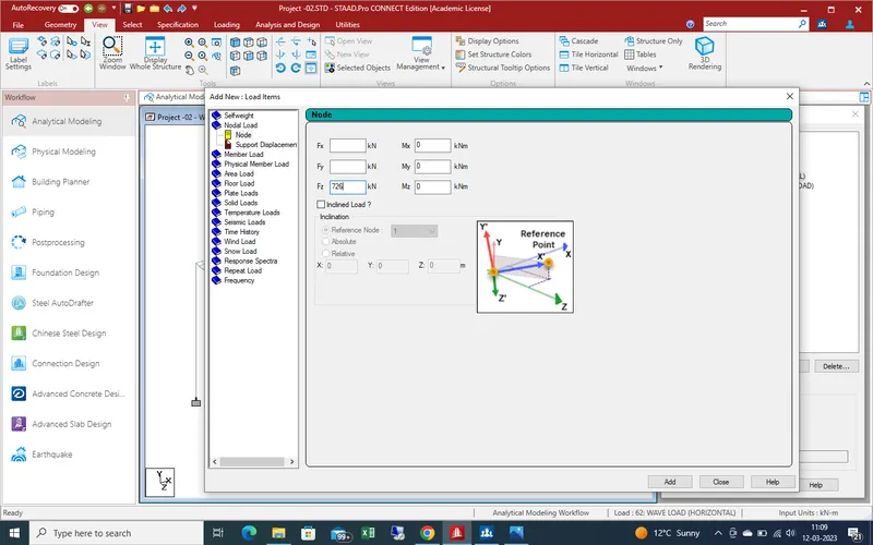
Wave load work on bridge as vertical load and horizontal load ,so define both load
we assume that the load is point load above calculate put the value as 726 kn in Z-direction for wave load in horizontal .
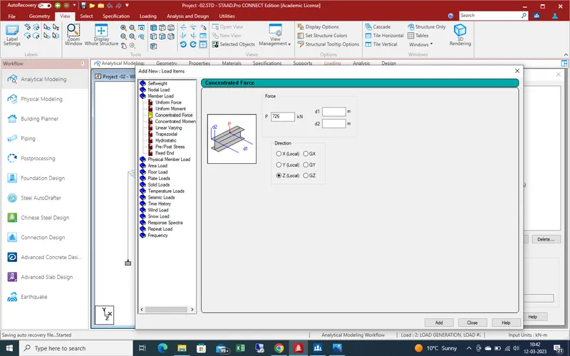
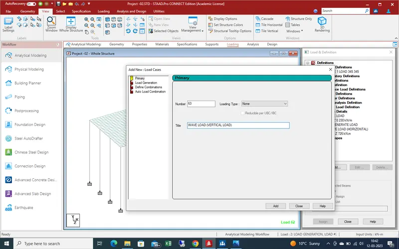
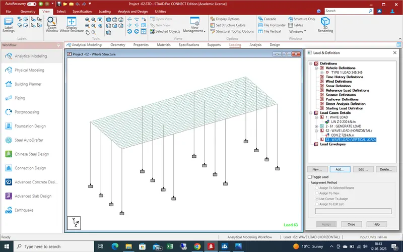
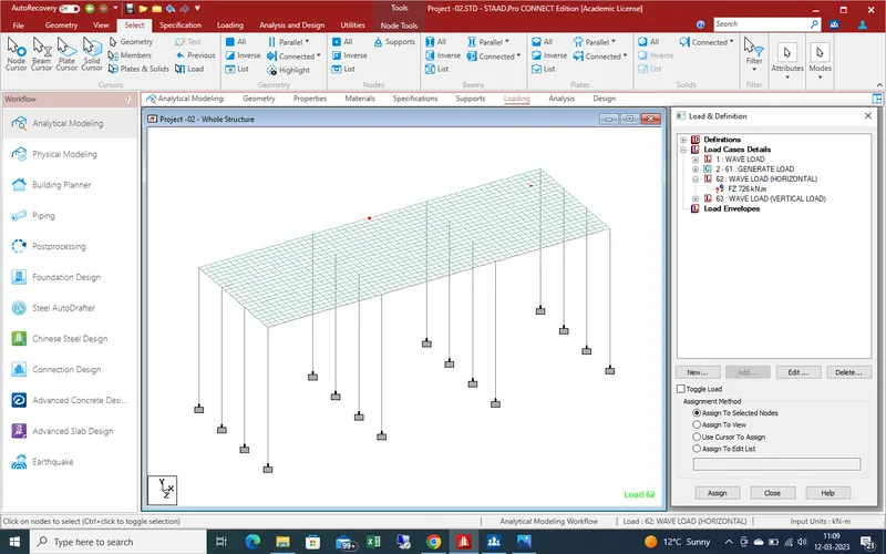
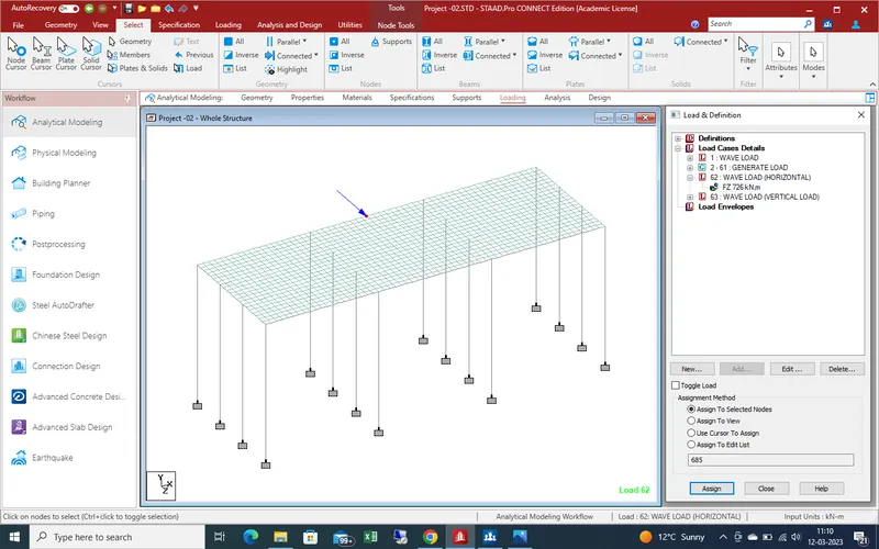
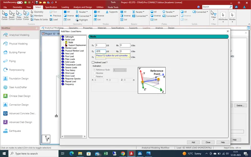
for wave load in Y -direction in negetive sign due to direction of loading is upward
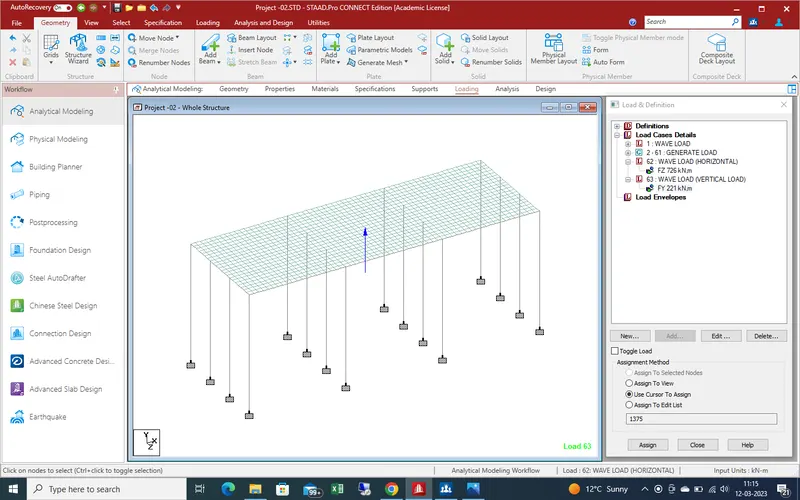
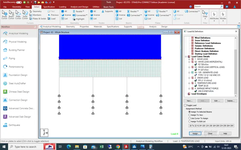
Now apply snow load as snow load is applied in plates as point load as showing in given pic
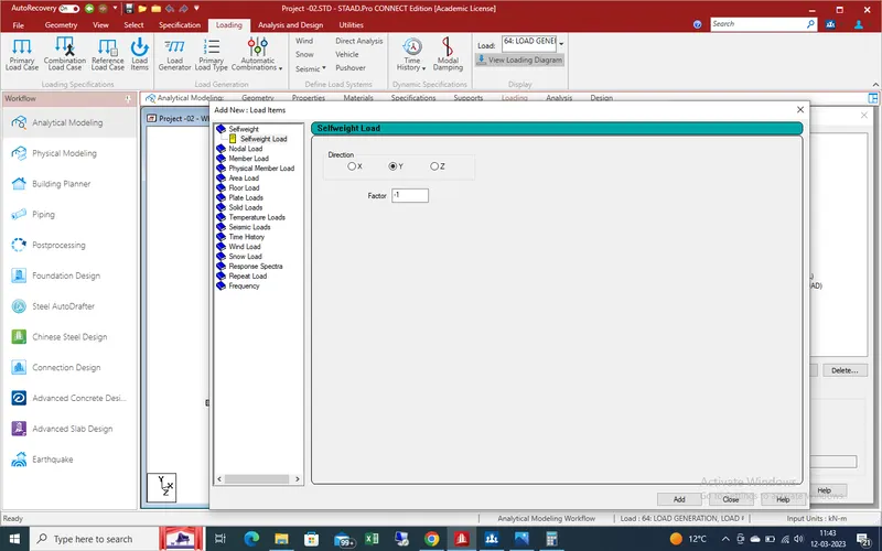
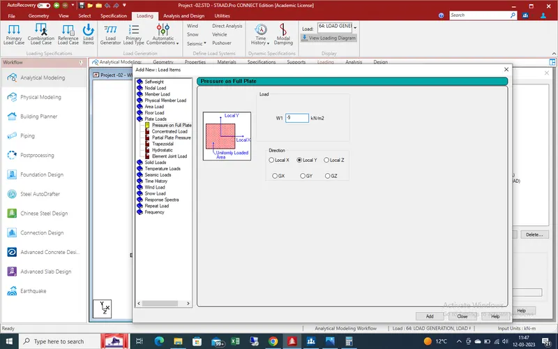
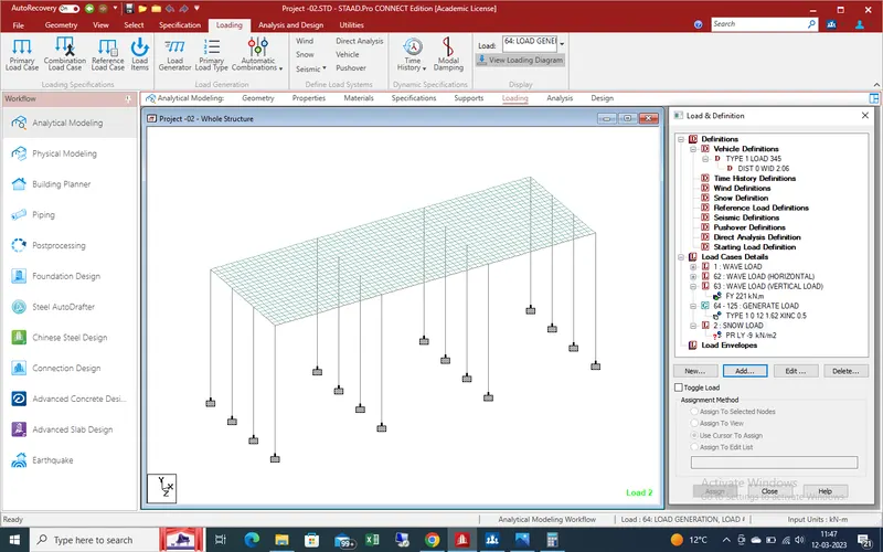
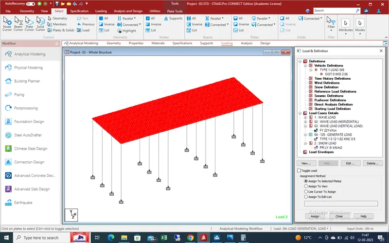
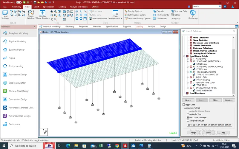
Add another load ,temperature load as given below pic .
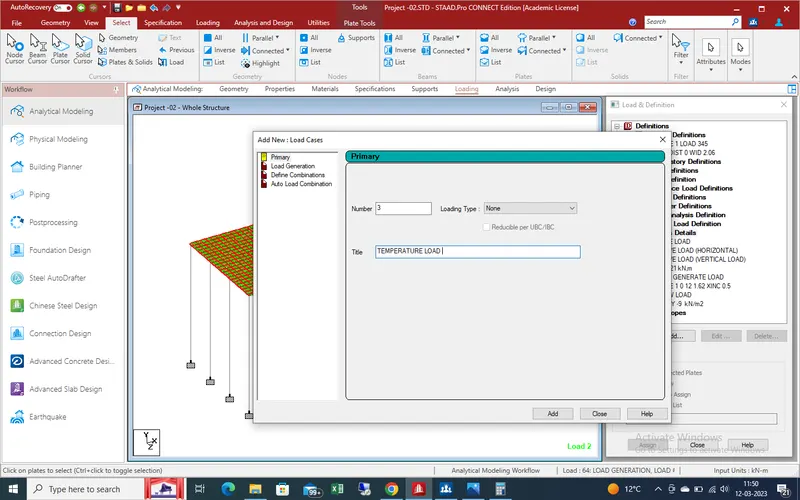
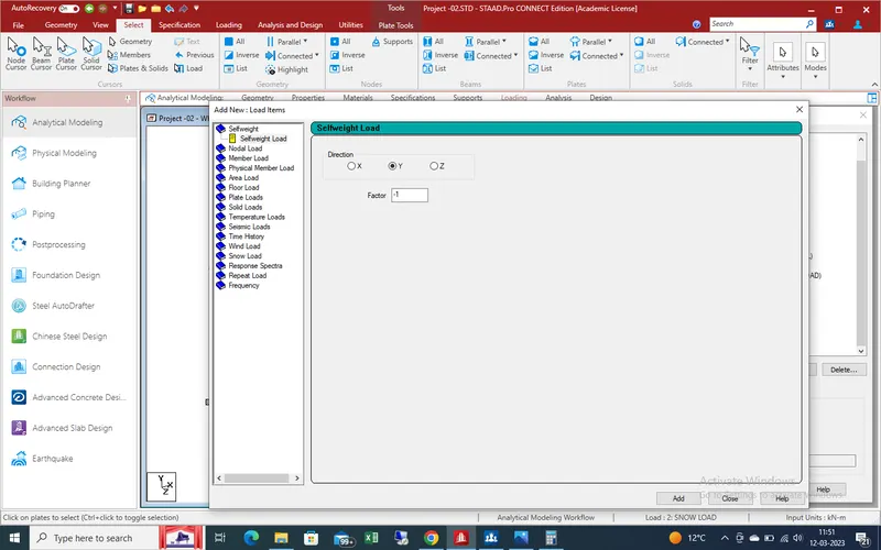
put the values for temp as above calculated
Select the all beam member as showing
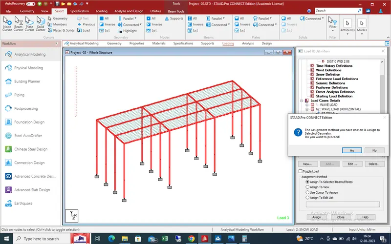
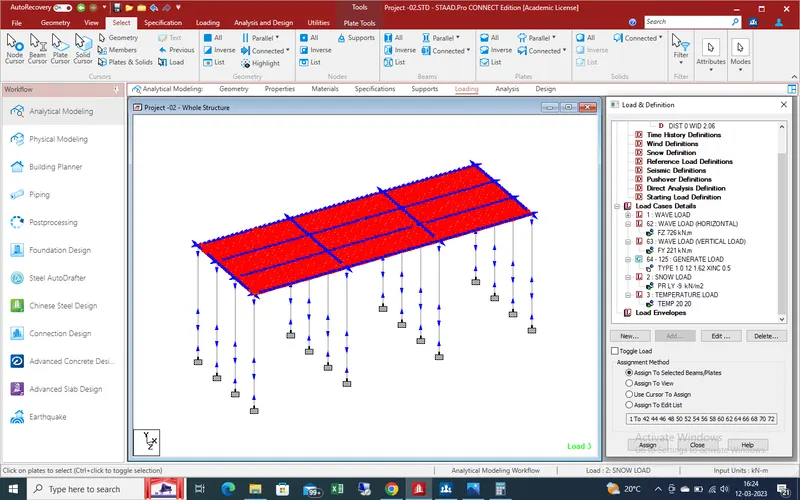
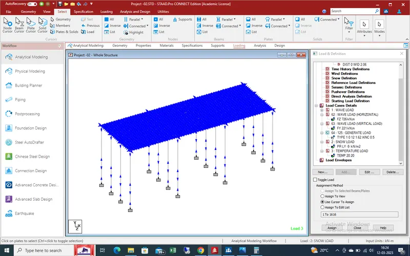
same as for plates
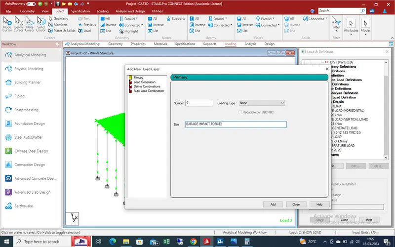
Now define the barge impact force on bridge
Barge impact load work as udl load over side the slab of bridge as showing given below pic
Now run analysis
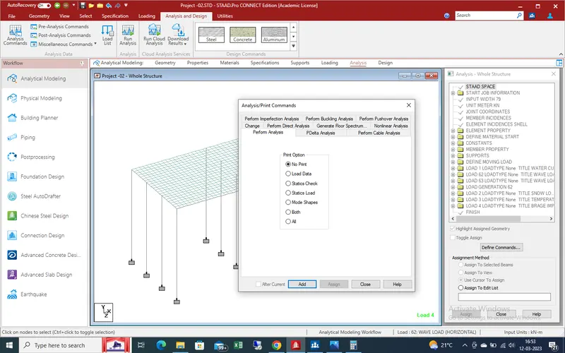
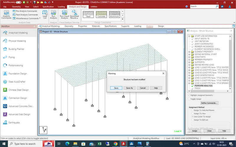
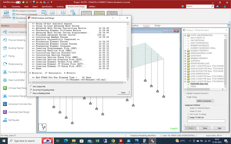
After run analysis ,there is no error so we go to post processing mode for get the results as given below
RESULTS :-
After run analysis we get the results as shown .
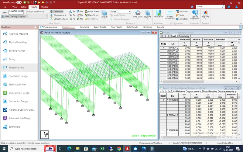
deflection due to water current load
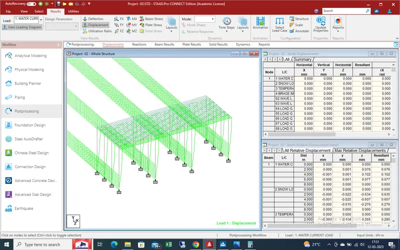
Displacement due to water current load
Shear force effect due to water current load .
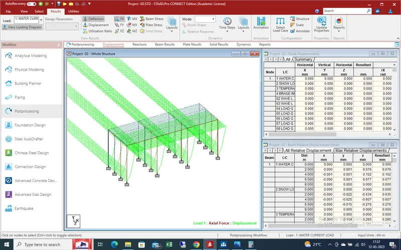
shear force effect in Y-direction
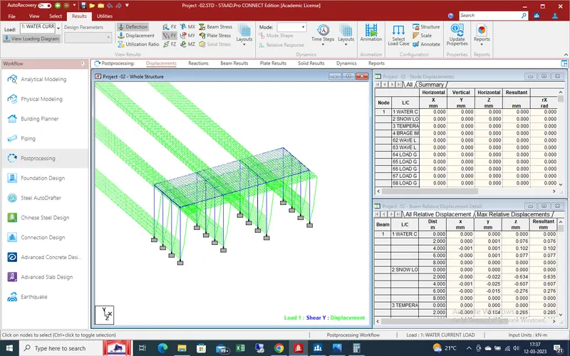
Shear force effect in Z-direction
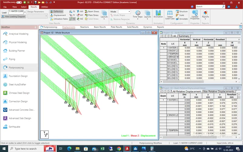
Bending moment effect due to water current load in x-direction
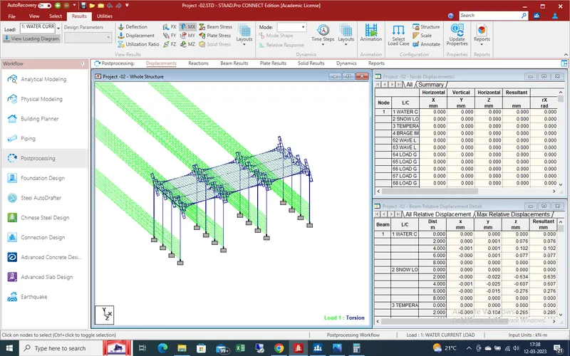
Bending moment effect due to water current load in y-direction
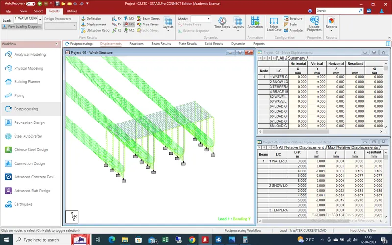
Bending moment effect due to water current load in z-direction
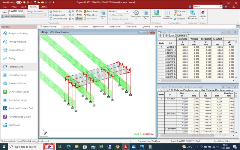
Beam stresses due to water current load on bridge
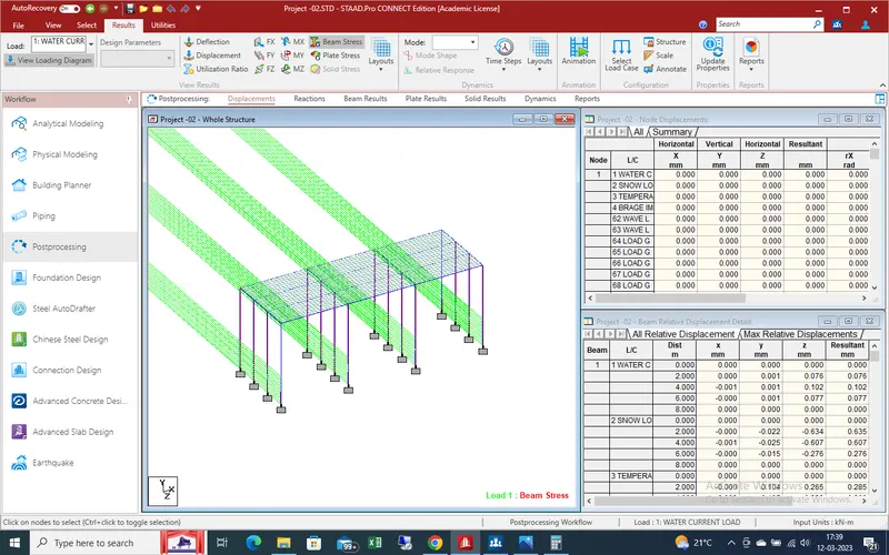
Deflection due to wave load on bridge
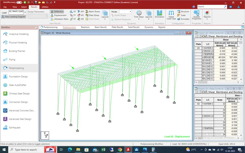
Shear force effect due to wave load
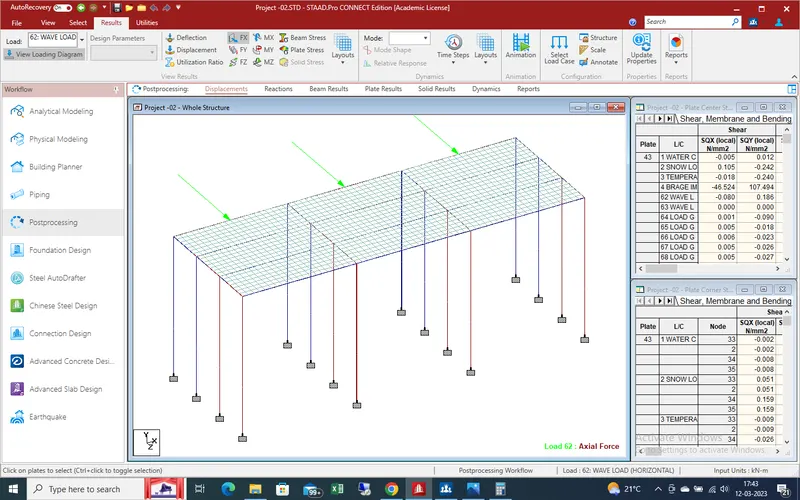
Shear force effect due to wave loading in Y-direction
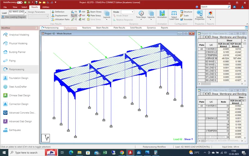
Shear force effect due to wave load in Z-direction
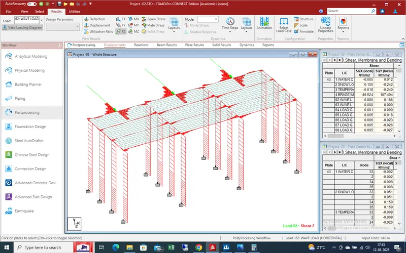
Mending moment in X-direction due to wave loading on bridge
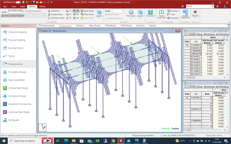
Bending moment effect due to wave load on bridge
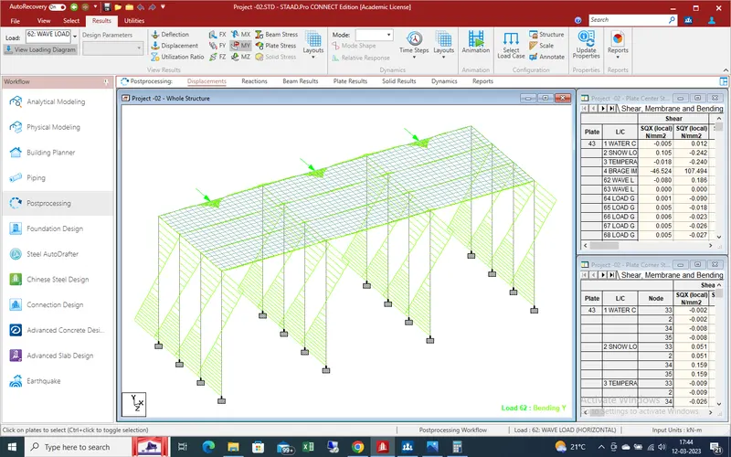
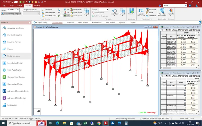
Bending moment effect due to wave load in Z-direction
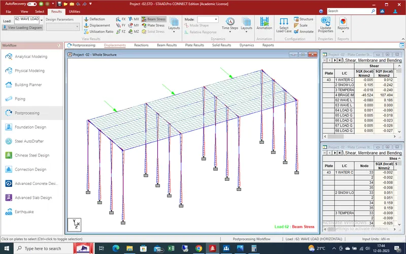
Beam stresses effect due to wave loading
Effects due to vertical vave loading in deflection
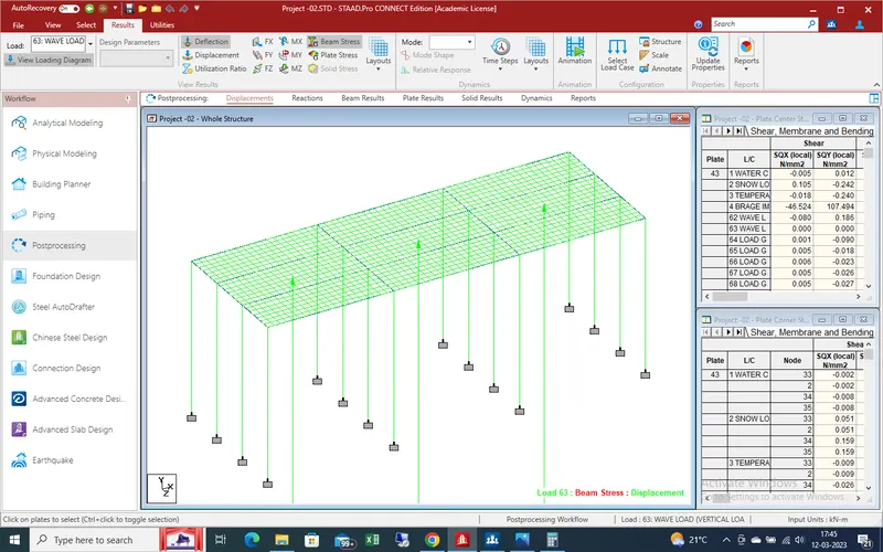
Beam stress due to wave loading
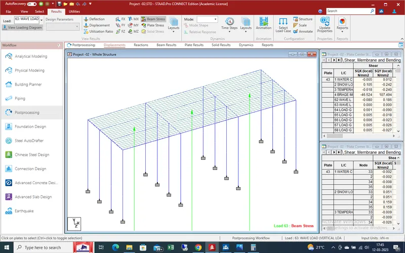
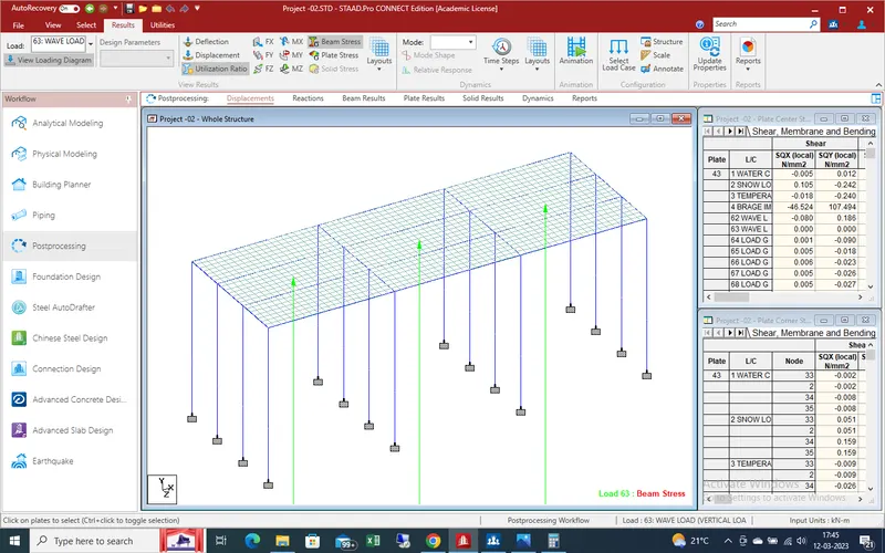
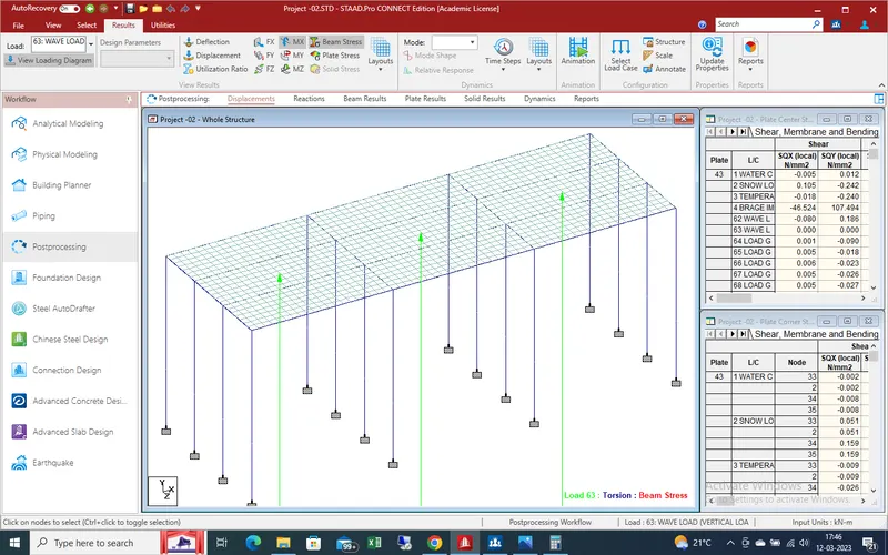
Bending momnet effect due to vertical wave load
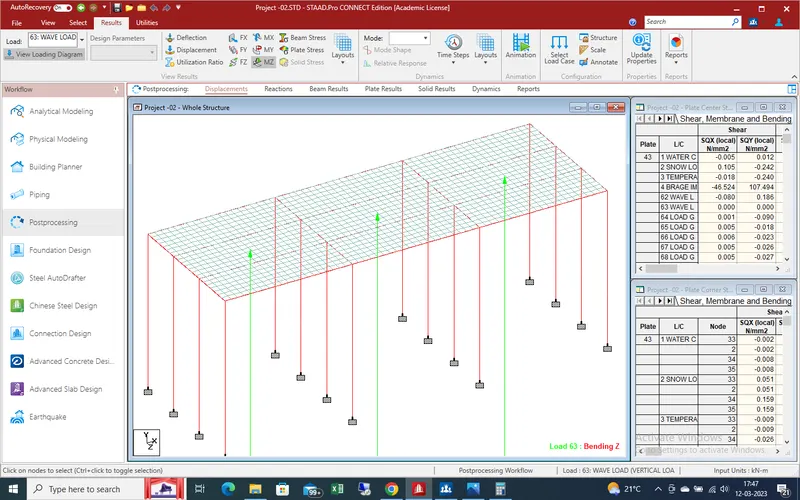
Deflection due to snow load
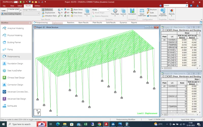
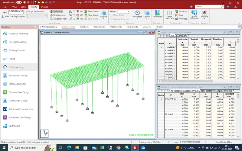
Deflection due to temprature differance on a bridge
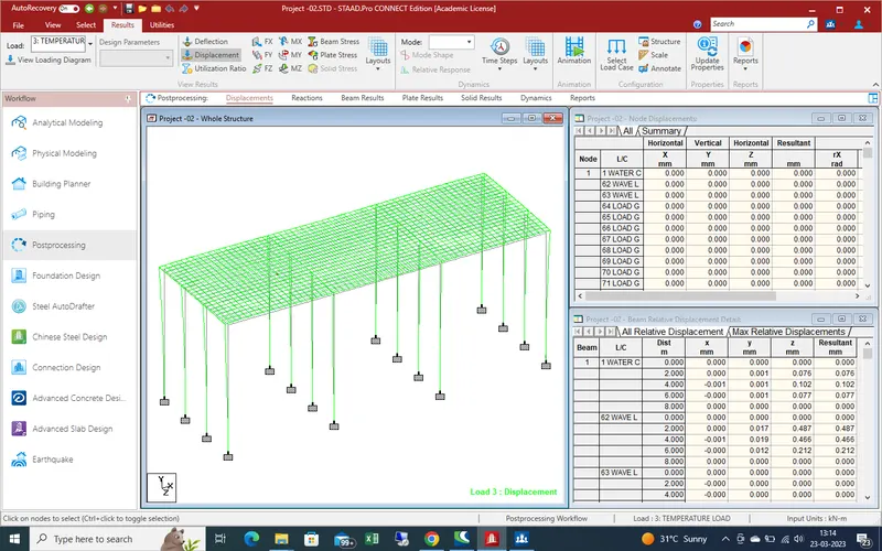
Displacement due to temp load on bridge
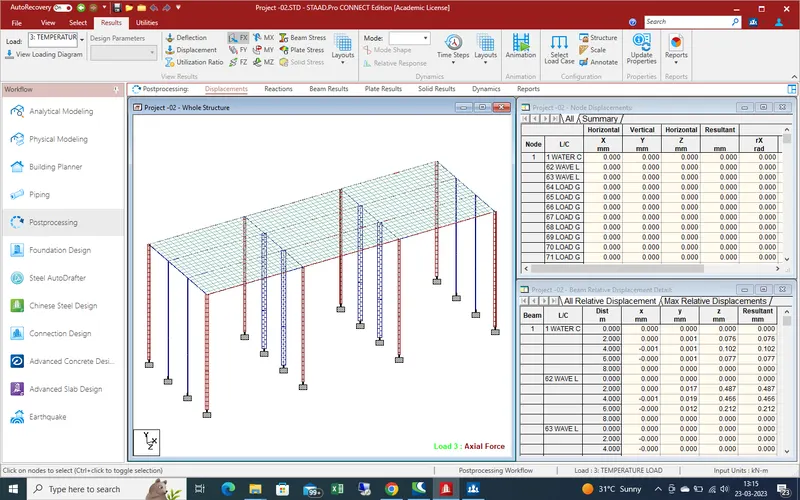
temp effect in shear in X-direction a bridge
Shear force effect due to temp in Y-direction
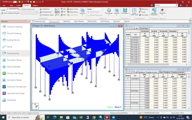
Shear force effect in temp in z-direction
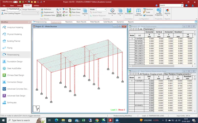
Bending moment effect due to temp in Y-direction
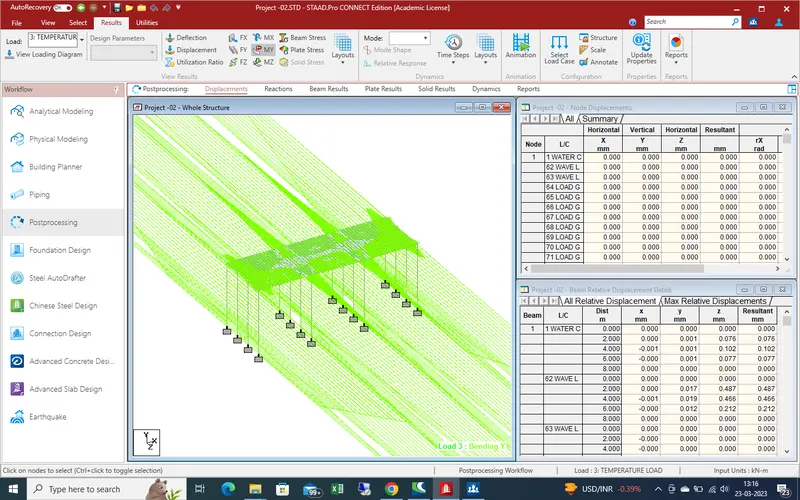
Bending moment effect in z-direction due to temp on bridge
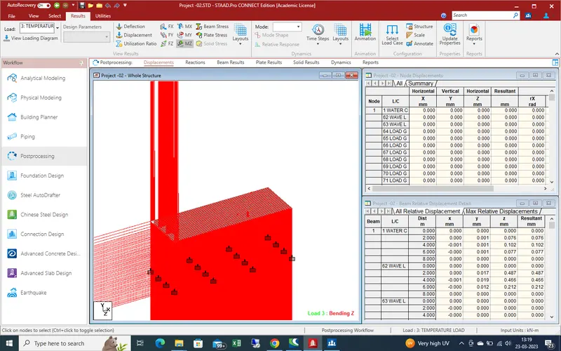
Beam stress effect due to temp load on bridge
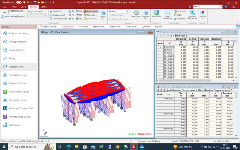
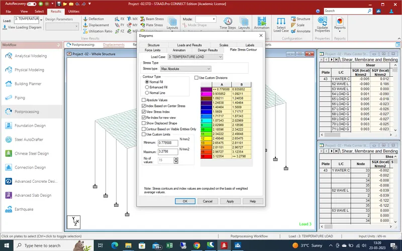
plate stress at max abslute due to temp load
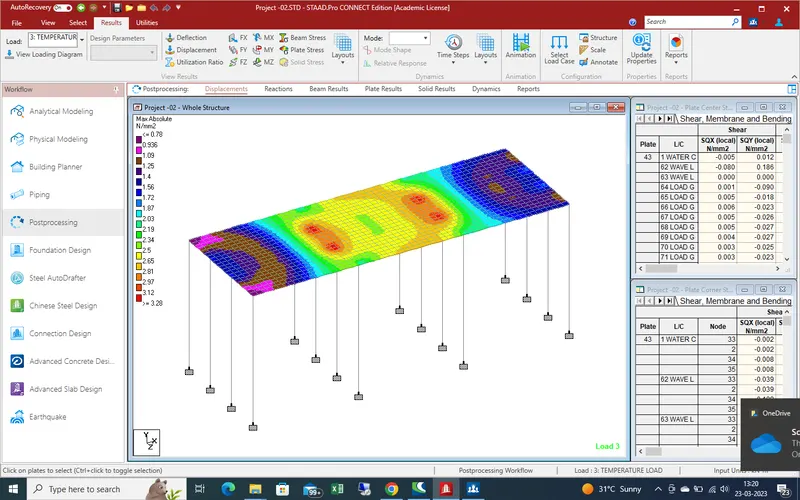
barage impact load ,deflection
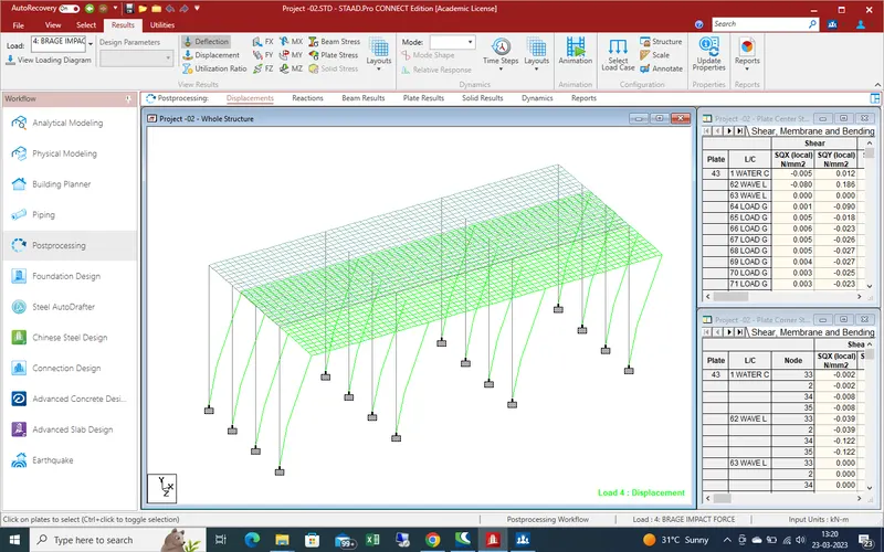
Displacement due to barage impact load
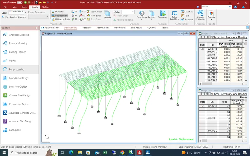
Shear force effect due to barge impact load
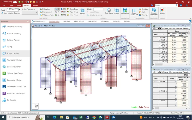
shear force effect due to barge impact load in Y-direction
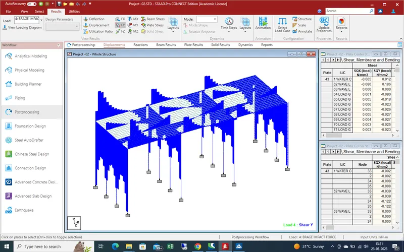
Shear force effect due to barge impact load in Z-direction
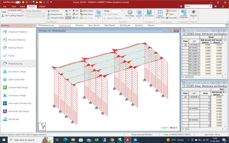
Bending moment effect due barage impact load in Y-direction
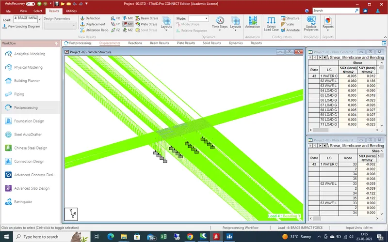
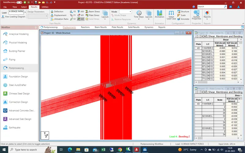
Bending moment effect due barge impact in Z-direction
Beam stress due to barage impact on bridge
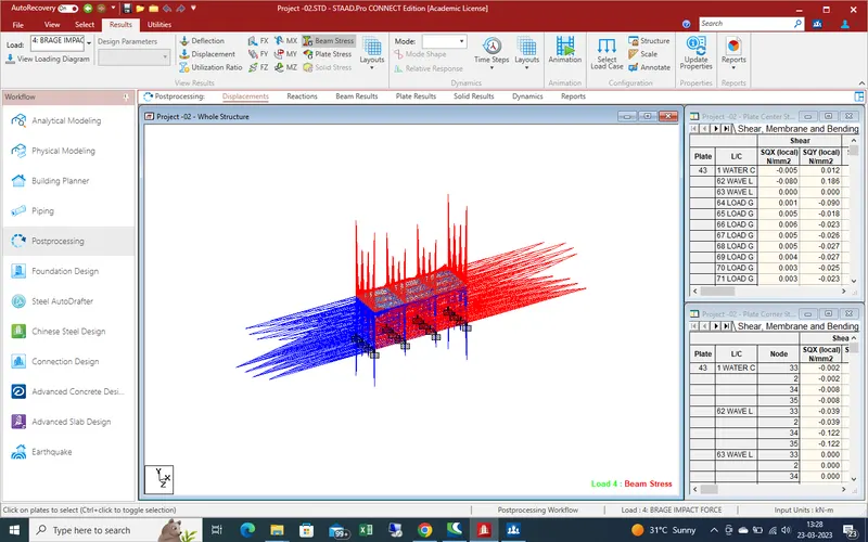
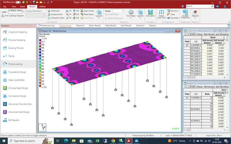
Plate stress due to barage impact force
Centrifugal force deflection on bridge
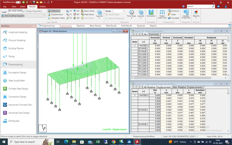
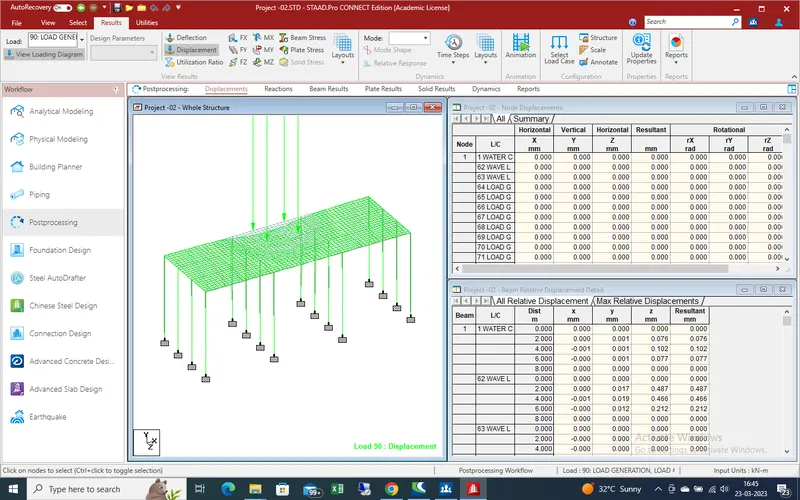
Displacement due to centrifugal force on bridge
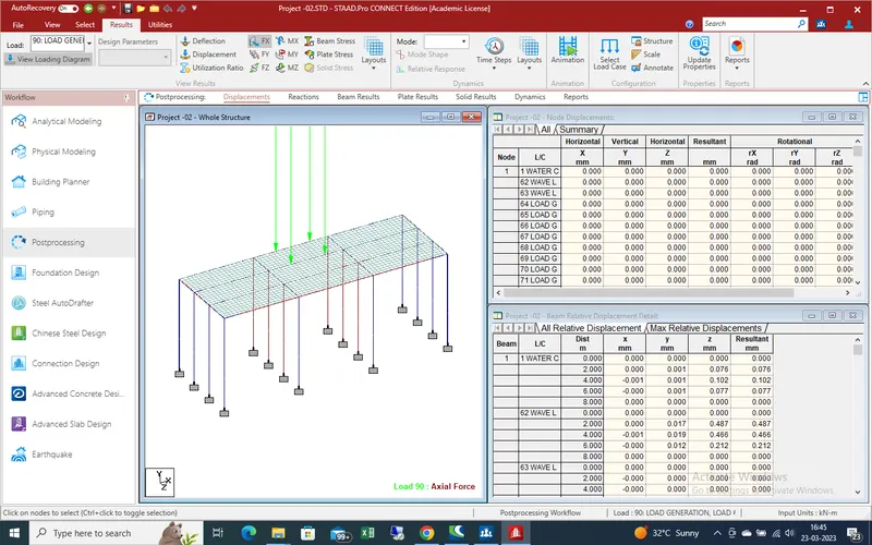
shear force effect due centrifugal force on bridge in x-direction
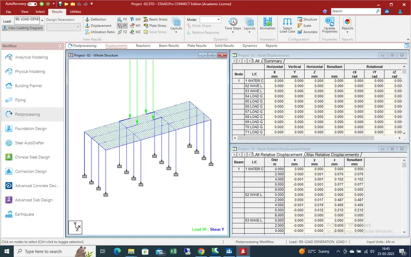
shear force effect due centrifugal force on bridge in y-direction
shear force effect due centrifugal force on bridge in z-direction
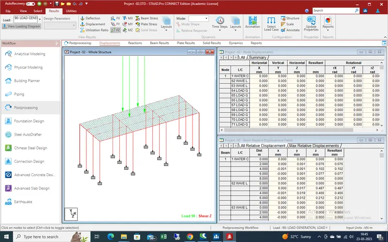
Bending moment effect due centrifugal force on bridge in x-direction
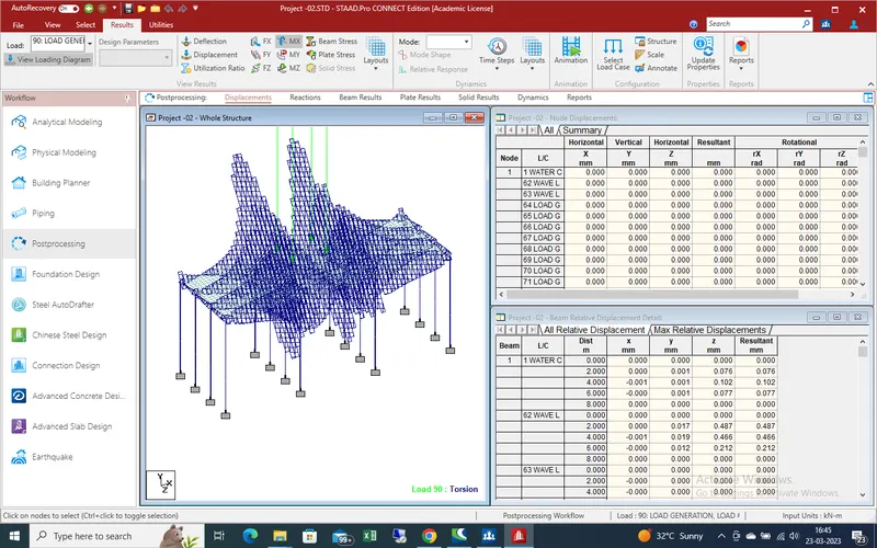
Bending moment effect due centrifugal force on bridge in Y-direction
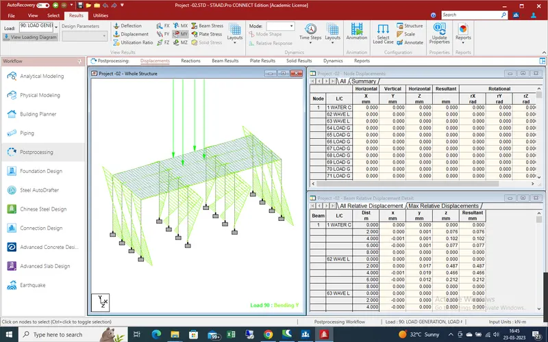
Bending moment effect due centrifugal force on bridge in Z-direction
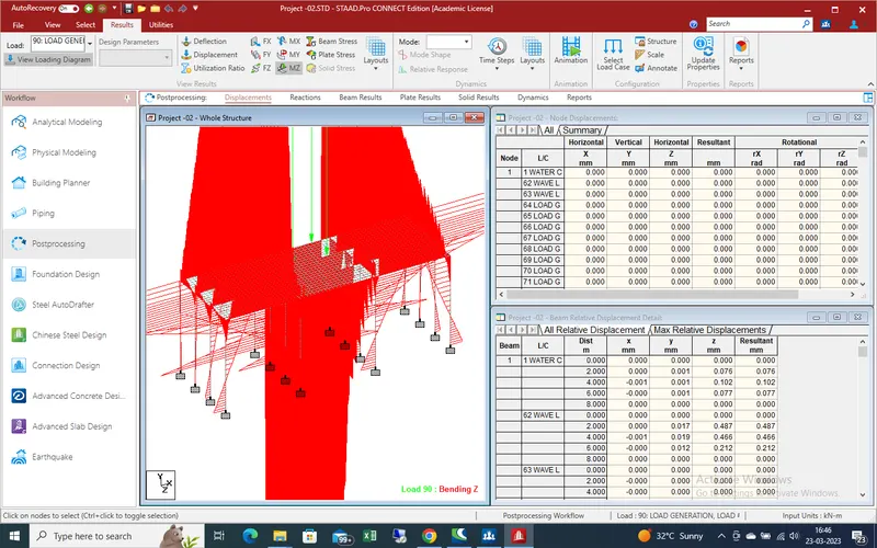
Beam Stress due to centrifugal load on bridge
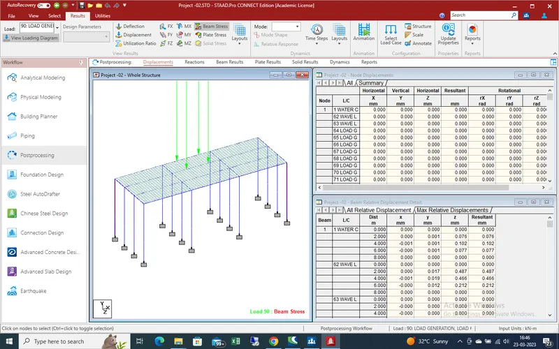
Plate stress on bridge due to centrifugal load
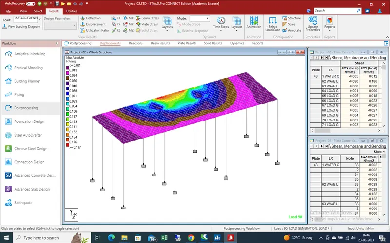
As given data we define different data which are required for different load and create the model and apply the load in different condition and get the appropriate results as shown in steps .