Project 2
Design of Tail lamp for Production vehicle
AIM
The aim of the project is to design a complete assembly of tail lamp considering all the parameters with lens, reflector, housing, wiring harness and other features on the housing to fix the tail lamp assembly with vehicle. CATIA V5 is used for the complete design of tail lamp assembly project.
INTRODUCTION
Tail lamp is the light function which shows the presence of vehicle mostly at night. It is one of major safety feature for vehicle. Tail lamp will have 3 functions at least , tail/stop, reverse and turn signal, Tail/stop is present in red colour lens and reverse and turn is present in clear lens. The lens and housing of the lamp is designed as per industry standard by checking all the regulations, While design of reflector is done in such a way that no light leakage happens inside the casing of light. Anti fog coating is done at the lens so that condensation does not happen and in reflector metalization is done for better reflection of light. Bulb are standard part.
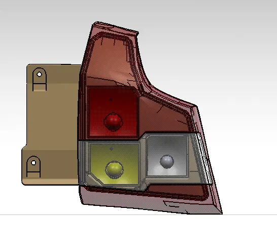
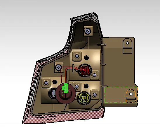
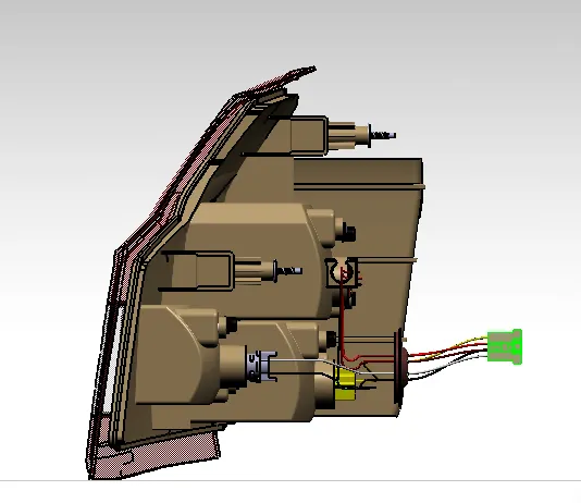
Tail lamp images are shown below:-
Front view:-
Back view:-
Side view:-
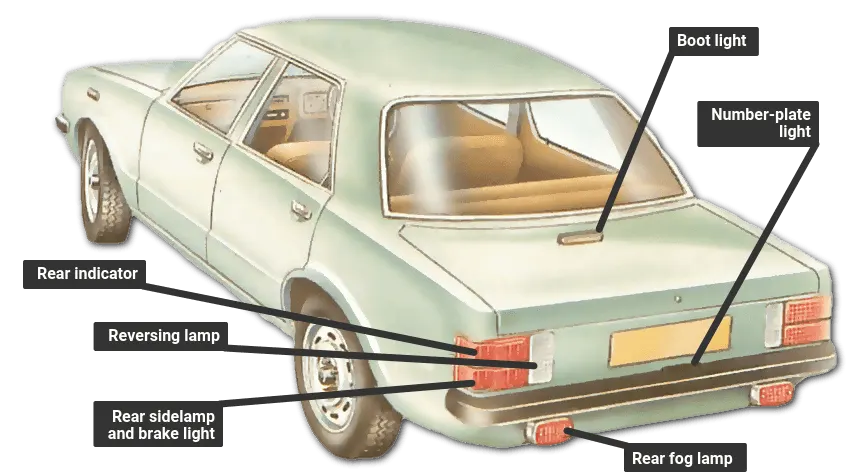
Position of the lights at rear of the car is shown below
Steps involved in manufacturing of the Tail lamp assembly are shown below:-
- Designing the solid body of the lens along with the welding track.
- Determing the shape and positions of the tail stop, yutn and reverse reflector.
- Desiging the solid body of thr reflectors
- Desinging the solid body of the housing for the lens along with welding track for the housing.
- Make screw bosses for reflector and housing.
- creation of red and clear lens
- presentation of final product
- Drafting of tail lamp assembly
- Bill of material
Design of the lens
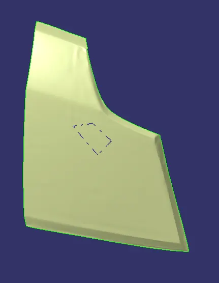
This the lens A surface , after getting the A surface first need to check the quality of the surface, if it has a irregular surface then need to correct the surface and make a good quality surface. The tooling axis of the input has to be determine before proceding and check whether it is clearing having the draft or not.
In this lens A surface was not at all satisfactory so need to main the surface and create the B surface for the same, after creating the B surface C surface need to be created to close the boundry which shown below with tooling direction
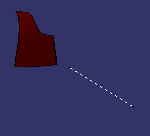
For this assembly tooling direction lies in Y axis
Draft analysis report is shown below
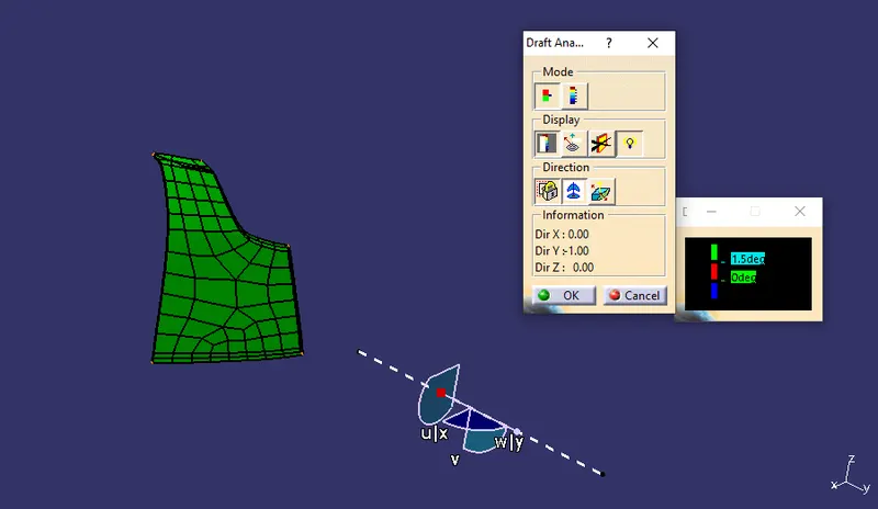
The part clears the draft of 1.5 degree
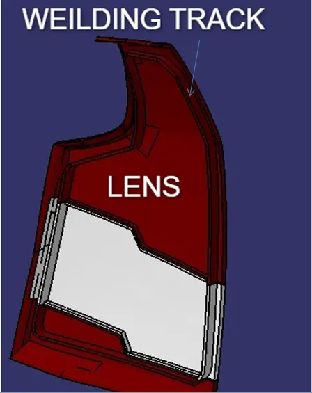
Next step is to create the weilding track for the Lens, Which is then joinned with the lens by union trimming. the image is shown below.
Design reflector for the assembly
Tail lamp consist of 3 major function:-
- Tail/stop function
- Turn signal
- Reverse function
Tail/stop function is in red lens and tail is used with headlight on time while the stop function activate when the driver press the brake padle, turn signal on when driver activate the switch while make a right or left turn and turn signal also works when hazard lamp is switched on. Reverse light turns on when the reverse gera is engaged.
To design the reflectors first we need to create the parabola at the back side of the parabola poitns are given and then the focal points are given so that the bulbs are placed then in the disired the parabola are trimmed to create the reflectors. Parameters and relation features are used to specify the diameter of the parabola so that in future some one wants to modify the parabola they can easily do that.
Next step is to add bulb in the focal points of the reflectors. Bulbs are Bop poarts so need to add the bulbs in the master file then with axis to axis translation they are placed in the reflectors. Bulbs which are used are speified below
- Tail/stop function:- W21/5W BULB
- Turn signal:- WY21W BULB
- Reverse function:- W16W BULB
Along with bulb , bulb holders , seating area were also imported. With the help of bulb seating area the bulbs are fixed to the housing with the help of union trimming.
After the creation of the reflectors It is placed at the required position on the housing and it is the most important step in designing the reflectors,As per the industry certain rules has to be followed which are minimum and maximum distance at which each function should be placed by considering all thses factors reflectors were positioned at required position following the industry standards.
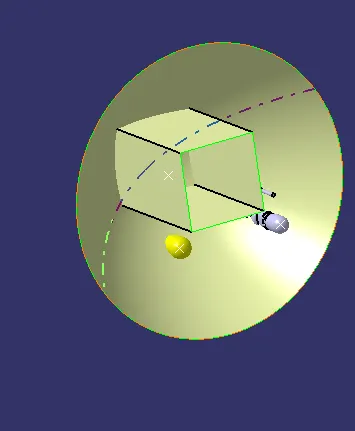
TAIL STOP
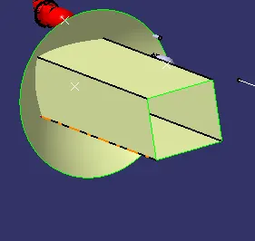
TURN SIGNAL
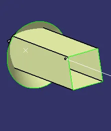
REVERSE FUNCTION
In the above image parabola and reflectors are shown which were created as per the industry standards like minimum focal length with the back of the reflectos. Shape of the reflector
Solid reflectors are shown in the image below.
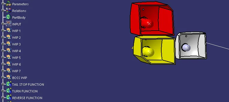
The above image shows the solid reflector with all the bulbs on it and with the tree structure of parametrs and relations, in WIP 1 the focal points and parabola creation is present,from WIP 2- 5 the creation of shape of reflectors are present and in WIP 6 and 7 the vent hole and reflector mounting is present.
After creating the reflectors flutes should be added on the reflector with power copy. Flutes are the external surface used to reflect the lights more better way.
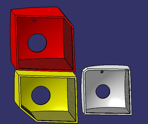
Flutes are added on the walls of the reflector at the back side of the reflector other type of flutes are added which cant be done using CATIA V5.
Design of Housing
Housing is the most important part of the light design because housing hold all the parts together and get fixed in the BIW surface. The first step of creation of housing is to create master section , projection of surrounding , weilding track of lens solid body were taken into consideration and then sketch was developed by referring to which the housing can be designed
Hot plate weilding technique was to be used to attached the housing with the lens to accomodate both lens and housing together.
While creating the housing many industry factors were taken in consideration to make sure their is no light leakage happening inside the lens.
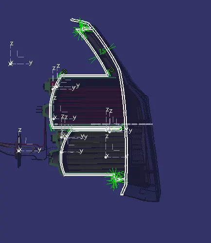
Master section of housing is shown below
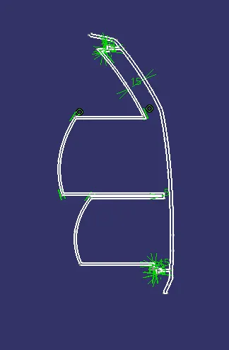
VERTICAL MASTER SECTION
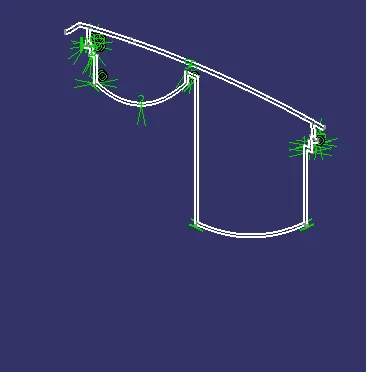
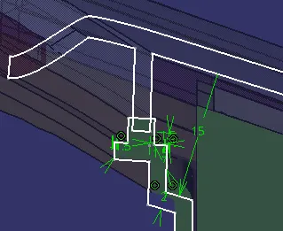
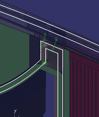
HORIZONTAL MASTER SECTION
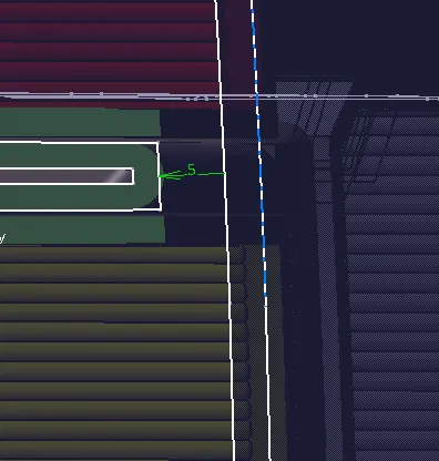
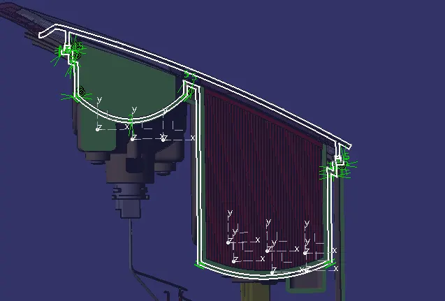
In the designing of housing a diatance of 15mm is manintained between the housing otter surface to the lens inner surface so that when hot plate weilding takes place it do not affect the housing surface as it is a part of styling. The image below shows the approximate distance of 15mm between the housing and lens. In the middle portion 5mm is manintain to aviod the light leakage.
VERTICAL SECTION
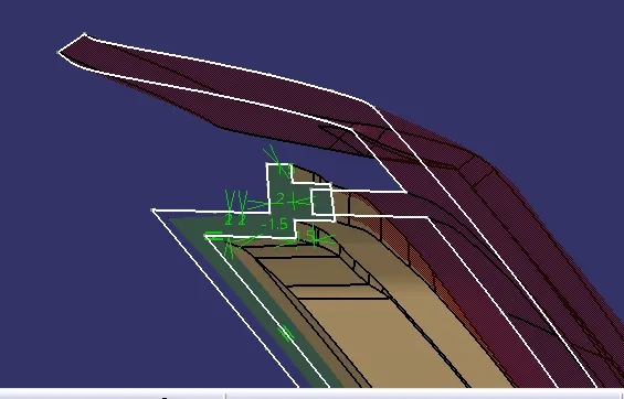
HORIZONTAL SECTION
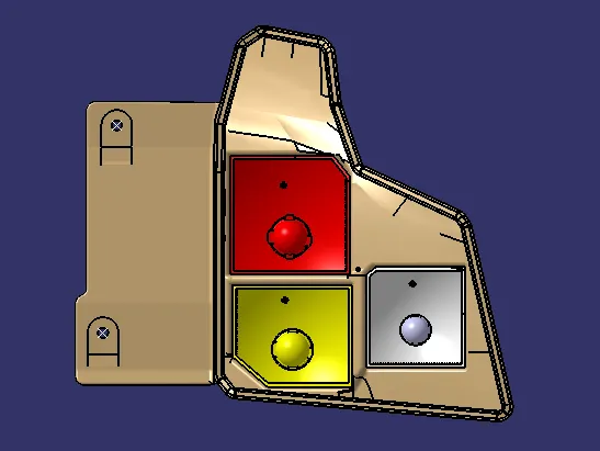
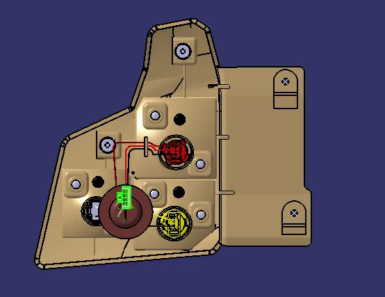
Different views of the housing
Front view
Rear view
Side view
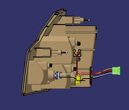
In the above image the final housing is shown with all the fixation screw boss vent area and the dog house seperate images of the same is shown below
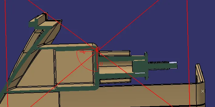
Dog House
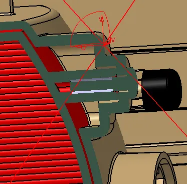
BOSS,BOSS HOUSING WITH M4 SCREW
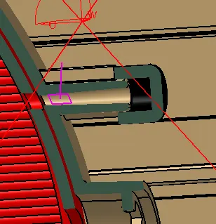
VENT CAP
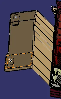
POSITIVE MOUNTING
Above images shows the mounting area of the houisng to biw and the mounting of reflector to housing by considering 3-2-1 principle.
Ribs are provided for the strengting of the mountings and to hold the reflector housing.
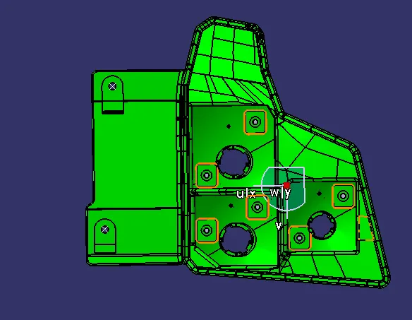
Draft analysis of housing is shown below
Design of Wiring Harness
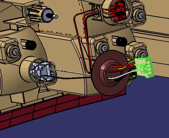
Above image shows the wiring harness of the housing with wire routing feature. In every vehicle 5 wire comes from connector 1 for tail, 1 for stop, 1 for turn , 1 for reverse, and 1 ground.
Colours of wire for each function
- Tail/stop function- 1 maroon for tail , 1 red wire for stop , 1 black wire for ground
- Trun signal- 1 yellow wire for turn , 1 black wire for ground
- Reverse function- 1 white wire for reverse, 1 wire for ground
Grommet is designed at the back side of the housing which connects between pole connector and the wire coming out from the housing. At gormmet aditional wire can also fixed for the lamp
Final Product
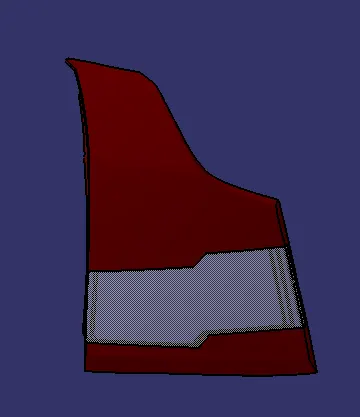
The above image showns the insert moulding section

The above image showns the proper view of insert moulding. At first the red lens will be moulded and then the white lens will be moulded , in insert moulding we have to provide the bur so that red colour dont flow into white part.
parting line
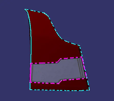
When core and cavity joins and material is filled then one joining line forms which can be seen easily in the plastic components. It is the boder line in which the draft angle is aslo changed.It spits the cre and cavity from each other. In the above figure parting line for white lens and red lens is shown.
Reflector Final
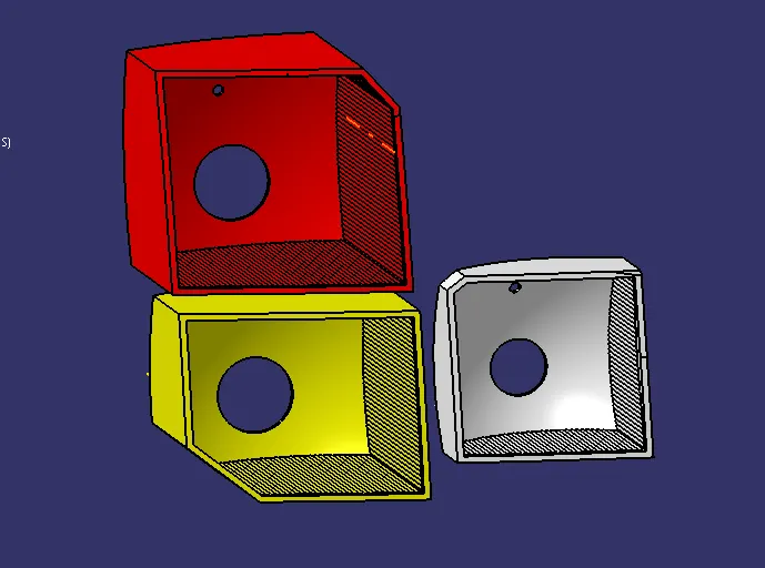
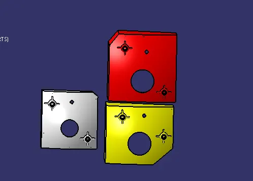
In the above shown image the reflector is finilized with flutes on the surface it is created to reflect the lights in more better way.
Assembly and child part Drawing
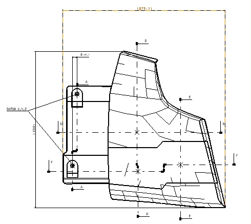
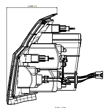
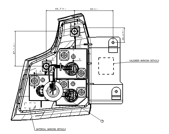
The above image shows the packing and the mounting dimensions
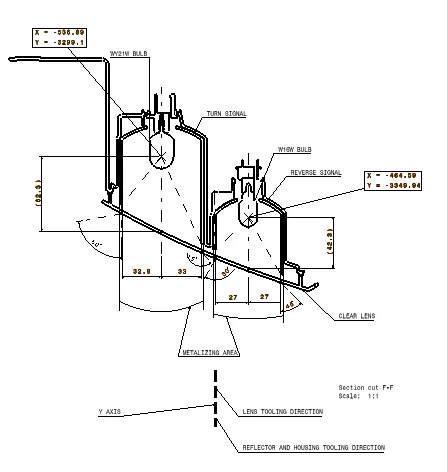
In this image the regulaton and focal coordinate with metalizing area are shown the above image has Turn signal and Reverse lamp with tooling direction of housing, reflector and lens. In horizontal section
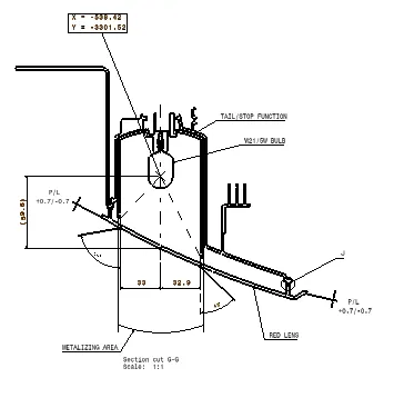
In this image the regulaton and focal coordinate with metalizing area are shown the above image has Tail and stop function.In horizontal section.
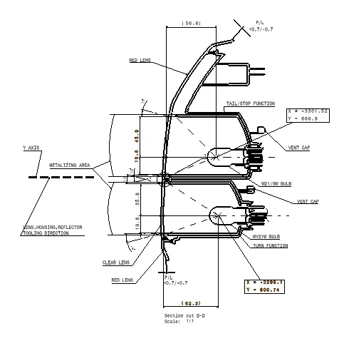
In this image the regulaton and focal coordinate with metalizing area are shown the above image has Turn signal and Tail stop with tooling direction of housing, reflector and lens. In vertical section
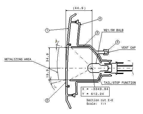
In this image the regulaton and focal coordinate with metalizing area are shown the above image has reverse function .In horizontal section.
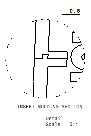
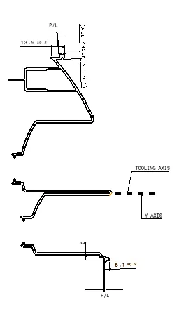
Insert moulding section
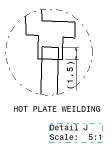
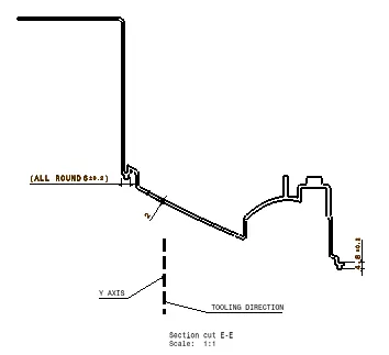
Hot plate weilding section
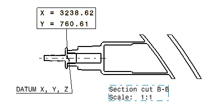
Dog house
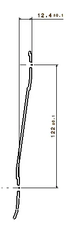
Positive Mounting
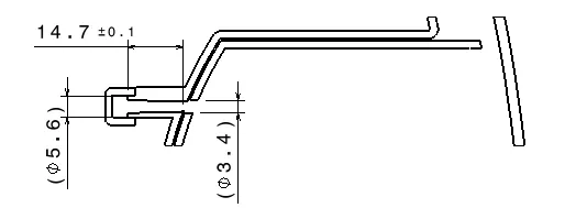
Vent area
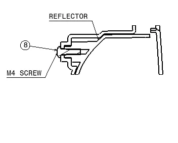
Reflector mounting
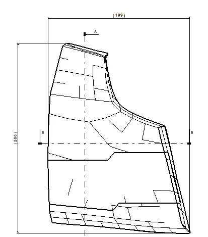
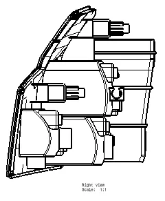
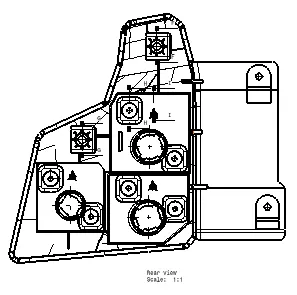
CHILD PART DRAWING
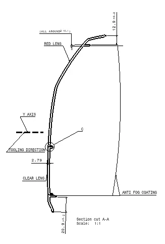
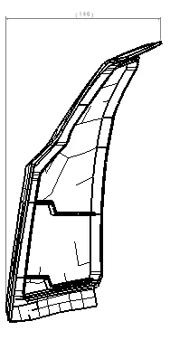
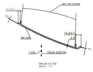
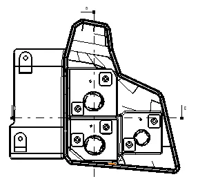
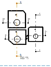
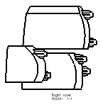
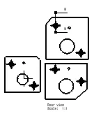
BILL OF MATERIAL
A bill of material is the list of product used in the assembly , name of part, quantity, any remarks is there or not any assembly can not happen without BOM. The actual reprentation of BOM is shown below.
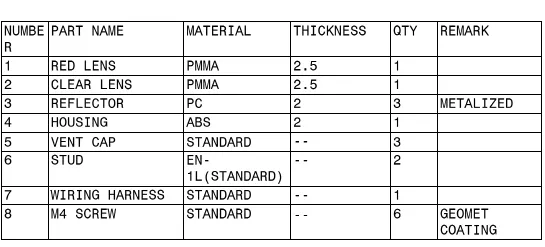
Assembly drawing BOM

Child Part BOM
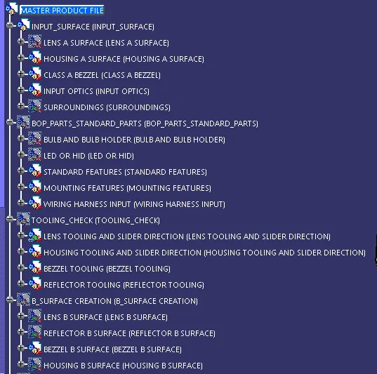
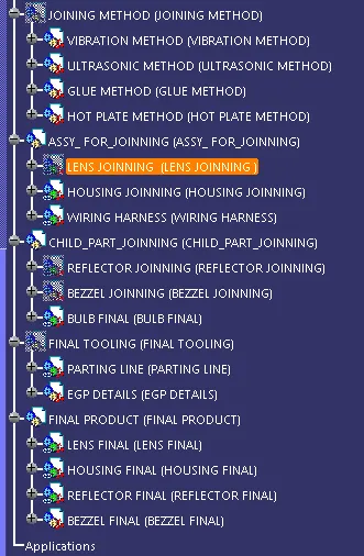
Tree structure
Conclusion
The design of light assembly is completed following industry standards:-
- Solid for lens and housing was made which can be attached to each other using hot plate weilding section
- Attachment features like mounting, bosses were designed at the back side of housing
- Draft analysis is performed
- 2D drwaing is made for child part and assembly
- BOM was also presented to know all the information