Project 2
Aim of The Project : To Model & Analyse the Bridge Section which is having 4n span of 10m length for Various Loadings such as Water current forces ,Centrifugal forces, Wave forces, Snow loads, Temperature load & Barge Impact load acting on the bridge There are various Values and Parameteres given in the problem which is briefly described below. We have to Calculate each and every loadings for different cases and analyse the structure.
Given Values :
- HFL above foundation level - 4m
- Span of bridge - 10m
- Mean Velocity - 2.5 m/s
- Width of carriage way - 9m
- Crest height - 3m
- The deck is supported by - 4 girders
- Height of each girder - 1.6m
- Top and bottom width - 2.0m
- Thickness of web - 0.3m
- Constant r - 5
- Cva - 3
- Strom elevation - 8.5m
- Cr - 0.4
- Bridge subjected to - 70R tracked vehicle
- Radius of curvature in bridge - 2m
- Design Speed of Vehicles - 50 km/hr
- Pier Size - 1.2 x 1.2 m
- Width of deck slab - 10.5m
- Thickness of deck slab - 1.5m
- Depth of accumulation of snow - 1.250 m
- The bridge is subjected to snow load - Settled Snow
- β <30
- Dead weight of vessel - 25000T
Introduction : As we Know Staad Pro is Designed and Maintained by Bentley Systems Software Company, Staad Pro is used for Structural Analysis and Design Purposes, we have to analyse the structure and provide different analysis results for Different Loadings.
Procedure :
CALCULATION OF WATER CURRENT FORCES
V is Maximum Velocity of current at the point where the pressure intensity is being calculated
V = (√2) x Mean Velocity
V = (√2) x 2.5 = 3.536 m/s
According to IS Code 78-2000 Section VII table No 4 Page No 21 is value of K is 1.5 for Rectangular Piers
k = 1.50 for Rectangular Piers
Water Current Forces = P = 52 x k x V^2
P = 52 x 1.5 x (3.536)^2
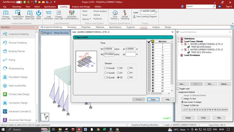
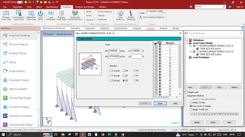
P = 975.000 Kn / M^2.
This Load must be applied in the model as water current load up to the height of 4m as HFL provided is 4m above the ground.
---------------------------------------------------------------------------------------------------------------------------------------------------------
CALCULATION OF CENTRIFUGAL FORCES:
C = W*(V)^2/127R
According to IRC 6 2017 70 R Tracked Vehicle is having a total load of 35T + 35T = 70T
Design Speed of Vehicle V = 50 km/hr (Given)
Radius of Curvature R = 2 m (Given)
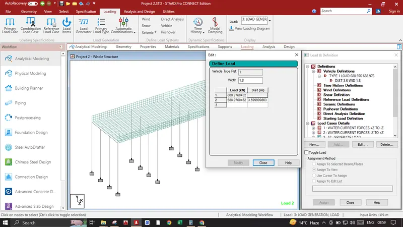
Hence, C = (70 x 50 x 50) / 127 x 2 = 688.976 KN.
---------------------------------------------------------------------------------------------------------------------------------------------------------
CALCULATION OF WAVE LOADS:
We have to calculate Δzh and Δzv
Δzh = ηmax-Centroid of I girder = 3 -(1.6/2) = 2.20 m
Δzv = ηmax-Elevation of Bottom Deck = 3 -1.7 = 1.4 m
Vertical Load Fv = R x Δzv x Av = 5 x 1.4 x (10.5 x (1.6/2)) = 58.80 Kn
Horizontal Load Fh = R x Δzh x Ah = 5 x 2.20 x (1.5 x 40) = 660 Kn
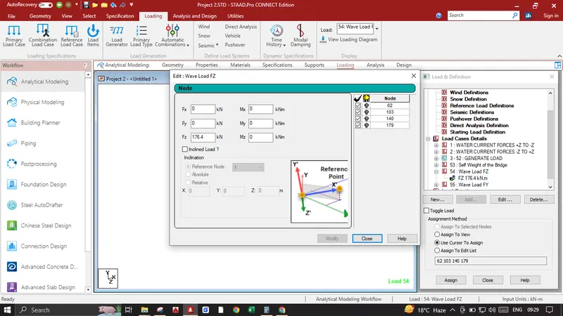
Max Vertical Load Fvmax = Cva x Fv = 3 x 58.80 = 176.40 Kn
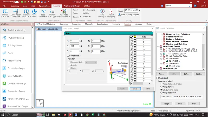
Max Horizontal Load Fhmax = (1+Cr x (N-1)) x Cva x Fh = (1+0.4 x (3-1)) x 3 x 660 = 1585 Kn
----------------------------------------------------------------------------------------------------------------------------------------------------------
CALCULATION OF SNOW LOADS:
Design Snow Load,
S = μ x So
Were,
So - is snow load on the ground.
μ - is Shape Coefficient.
So= Span of the Bridge x Depth of snow x Density of settled snow.
As per IS 875 Part IV code Density of settled snow is 2 -3kN/m3
We take the value of Density of settled snow is 3 kN/m3
So = 10 x 1.25 x 3
=37.5 kN/m (Per Span is Calculated)
As per IS 875 Part IV code value of Shape Coefficient for angle B<30 degree is, u = 0.8
S = u x So
=0.8*37.5
=30 kN/m Design Snow Load.
---------------------------------------------------------------------------------------------------------------------------------------------------------
CALCULATION OF TEMPERATURE LOADS:
Assuming the Location of the Bridge is in Delhi and Structure is designed for M40 Concrete.
Max temperature in the location as per IRC 6 Isotherm at the location=47.5°
Min temperature in the location as per IRC 6 Isotherm at the location=-2.5°
Effective Temperature Difference= (47.5- (-2.5)/2) +10
Effective Temperature Difference=35°
Stess due to temperature =α *ΔT*E
α = 11.27 x 10^-6
ΔT = 35°
E = 5000 x sqrt(40)
=11.27x 10^-6 x 35 x 5000 x sqrt(40)
Stess due to temperature =12.47KN/m^2.
Max Permissible Stress=(2/3)*0.7*(40)^(1/2).
Max Permissible Stress =2.95KN/m^2..
Hence the stress are restricted to 3KN/m^2.
Max temperature=47.5°
Min temperature=-2.5°
Positive temperature Difference ;
Temperature at Top=47.5°
Temperature at Bottom=(2.1/17.8)*47.5°
Positive temperature Difference=5.60°
---------------------------------------------------------------------------------------------------------------------------------------------------------
CALCULATION OF BARGE IMPACT LOADS:
(W) The Dead weight tonnage of Panamax vessel is 25000 DWT.
(V) = 50 km /hr – 13.88 m/sec.
Barge collision energy.
KE = 500 X CH X W X V2
= 500 X 1.25 X 25000 X (13.88)2
= 3010225000
Barge damage depth 'aB'.
ab = 3100 X [ (1 + 1.3 X 10⁻⁷ X KE ) x 0.5 - 1 ]
= 3100 X [ (1 + 1.3 X 10−7 X 3010225000)^0.5 - 1]
=58302.639 mm.
Barge Collision Impact force Pb.
Pb = 6.0 X 10⁶ + 1600 X (ab)
= 6.0 X 10⁶ + 1600 X 58302.639
= 99284222.4 N
= 99284.2 KN.
Uniform Force.
= Pb / length of bridge
= 99284.2 / 40
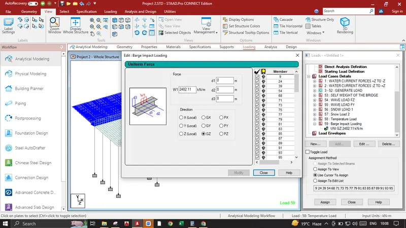
= 2482.105 kN/m
---------------------------------------------------------------------------------------------------------------------------------------------------------
Modeling :
- 1. Open Staad Pro and Create a new Project and select Metric in Unit, this will allow us to model the structure in metres as shown in the given diagram and get results in Kn.
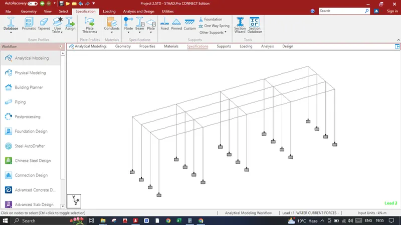
- 2. Input the origin node as 0,0,0 Select the node press CTRL C+ CTRL V input 12 in Y and press ok, create beam between two nodes, again select the beam and perform translational repeat no. of steps 3 and step spacing 3.5m in Z Direction press ok, Select all the newly created beams and again perform translational repeat no. of steps 4 and step spacing 10m in X Direction press ok, connect with top nodes with beams this will create our main girders, Now we have to Provide Supports in Pier Bottom Select all the bottom Nodes Click on Specification in Upper Tab Create a Fixed Support and Assign the Bottom Nodes to Fixed end Support. After all the steps the Model will look like this.
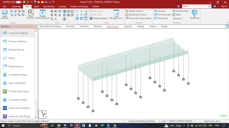
- 3. Now Create a Deck Slab Select the corner node of the Pier press CTRL C+ CTRL V input -0.5 in Z press ok. Select both the nodes and press CTRL C+ CTRL V input 0.5 in X press ok, create a plate inside the 4 nodes, now select the plate and perform Translational Repeat No. of steps 79, Step Spacing 0.5m in X Direction, again select all the newly created plates perform Translational Repeat No. of steps 20, Step Spacing 0.5 m in Z Direction. which creates our deck slab of 10.5m wide and 40m long.
- 3. Now Create a Parapet Wall Select the corner node of the Pier press CTRL C+ CTRL V input -0.5 in Y press ok. Select both the nodes and press CTRL C+ CTRL V input 0.5 in X press ok, create a plate inside the 4 nodes, now select the plate and perform Translational Repeat No. of steps 79, Step Spacing 0.5m in X Direction, again select all the newly created plates perform Translational Repeat No. of steps 3, Step Spacing 0.5 m in Y Direction. select all the parapet wall plates and press CTRL C+ CTRL V input -10.5 in Z press ok, which creates our parapet wall of 1.5m Height both sides. after this process model will look like this.
This Completes our Modelling Process
Assingning Specifications :
Creating Groups :
- 1. Click on Utilities and Click on Groups, again click on Create enter name as MAINGIRDERS and type Beam new group has been created, click on select click on Parallel under Beams click on parallel to X which selects all the Longitudinal Girders Click on associate to selected Geometry. again click on Create enter name as CROSSGIRDERS and type Beam new group has been created, click on select click on Parallel under Beams click on parallel to Z which selects all the Cross Girders Click on associate to selected Geometry. again click on Create enter name as PIERS and type Beam new group has been created, click on select click on Parallel under Beams click on parallel to Y which selects All the Piers Click on associate to selected Geometry. again click on Create enter name as DECKSLAB and type Plate new group has been created, Select all the deck slab plates Click on associate to selected Geometry. again click on Create enter name as Parapet Wall and type Plate new group has been created, Select all the Parapet wall plates Click on associate to selected Geometry.
Hence all the Groups has been Created it is lot easier for us to assign specifications for certain objects.
- Click on Specification Tab click on Define click on Taper and enter the values mentioned in the image below, this will create a specification for Main Girders select the Main Girders from groups and assign.
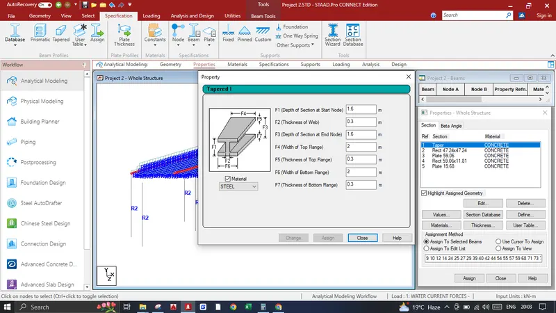
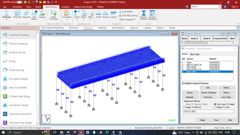
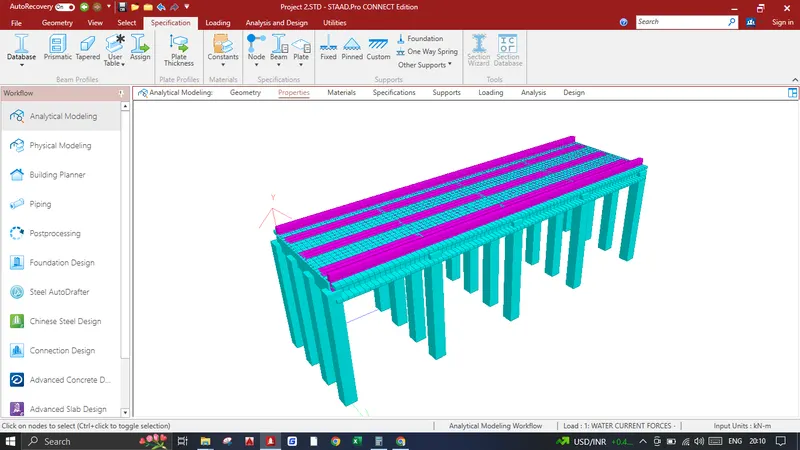
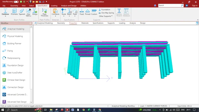
- Click on Specification Tab click on Define click on Rectangle and input YD-1.2 and ZD-1.2 this will create a specification for piers select the piers from groups and assign. Again click on Define click on Rectangle and input YD-1.5 and ZD-0.0.3 this will create a specification for Cross Girders select the Cross Girders from groups and assign. Again Click on Thickness and add a plate of 1.5 m click ok this will create specification for Deck Slab select the deck slab from groups and assign. Again Click on Thickness and add a plate of 0.5 m click ok this will create specification for Parapet Wall select the Parapet Wall from groups and assign. After Assigning all the specifications the model will look like this.
Adding Loadings:
Adding Water Current Forces:
- Click on Load Cases Details Click add write name WATER CURRENT FORCES +Z TO -Z click add again click add select Member Load , under member load select Trapezoidal and input the values mentioned in the image below.click add, apply these loadings in the piers as we can see the water current forces are applied upto the height of 4m that is the HFL of the Bridge.
- Click on Load Cases Details Click add write name WATER CURRENT FORCES -Z TO +Z click add again click add select Member Load , under member load select Trapezoidal and input the values mentioned in the image below.click add, apply these loadings in the piers as we can see the water current forces are applied upto the height of 4m that is the HFL of the Bridge.
Adding Centrifigual Loading:
- 1. Click on Loadings click on Vehicle Definitions, click add and give properties as given in the image below.
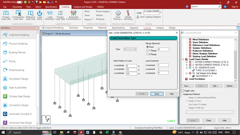
- 2. Click on Load Cases Details Click add Click on Load Generation Enter 50 in No. of Loads to be generated click ok. Again click add and give properties as given in the image below.
- 3. Click on Load Cases Details Click add write name Self Weight click add. Again click add and provide sewlfweight in -Y Direction.
Adding Wave Loading:
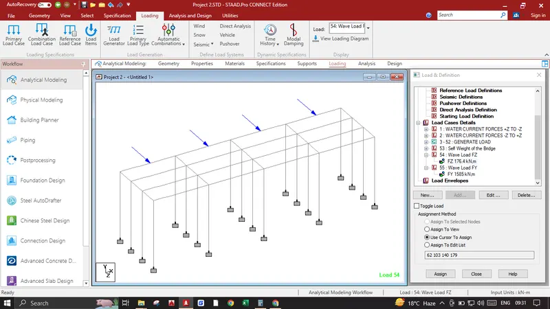
- 1. Click on Load Cases Details Click add write name Wave Load FZ click add. Again click add click nodal load and follow the image below. Apply this loading on the center of the longitudinal girders nodes.
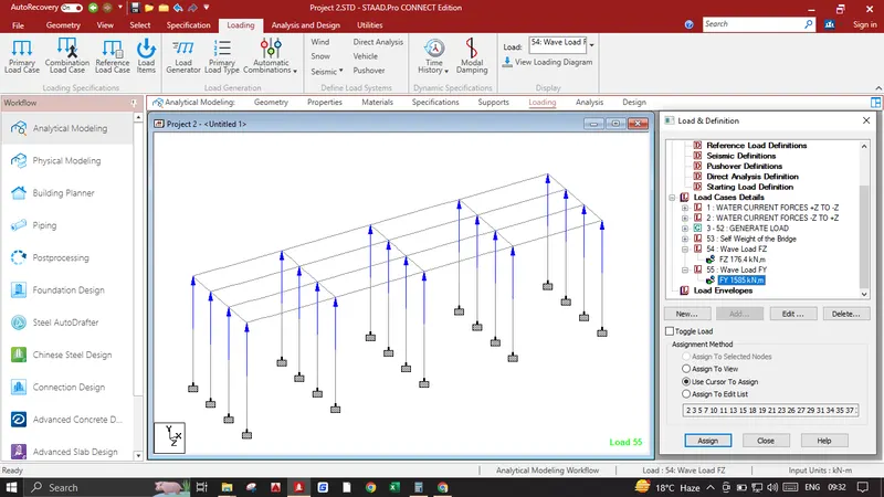
- 2. Click on Load Cases Details Click add write name Wave Load FY click add. Again click add click nodal load and follow the image below. Apply this loading on the center of the Piers nodes.
Adding Snow Loading:
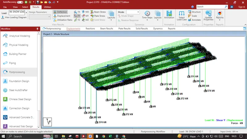
- 1. Click on Load Cases Details Click add write name Snow Load click add. Again click add click Member Load and follow the image below. Apply these loads in the longitudinal and cross girder beams.
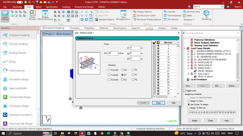
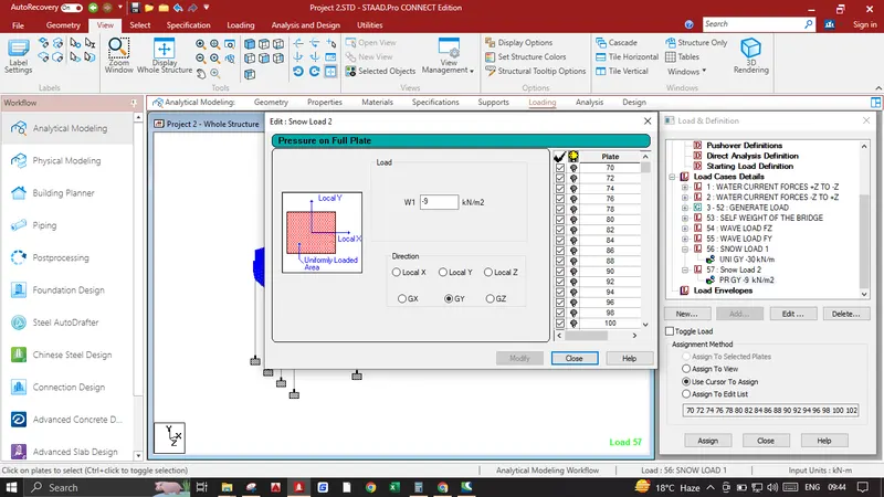
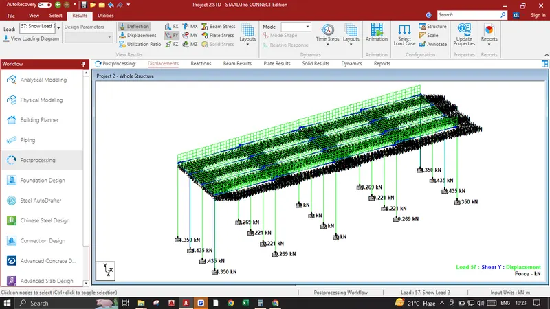
- 2. Click on Load Cases Details Click add write name Snow Load 2 click add. Again click add click Plate Load and select Pressure on Full Plate and follow the image below. Apply these loads over all plates.
Adding Temperature Loading:
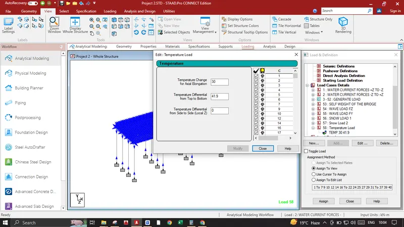
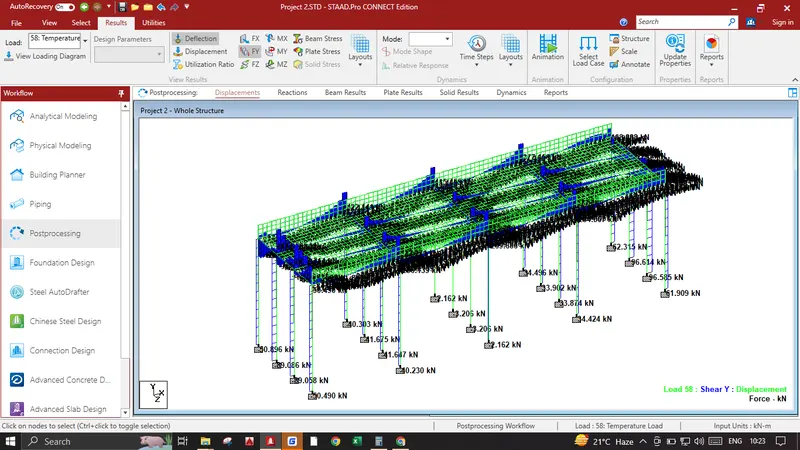
- 1. Click on Load Cases Details Click add write name Temperature Load click add again click add select Temperature Loads and give the values of Temperature Change along Axial Elongation =30 and Temperature Differential from Top to Bottom=41.9. and Add. Assign to view.
Adding Barge Impact Loading:
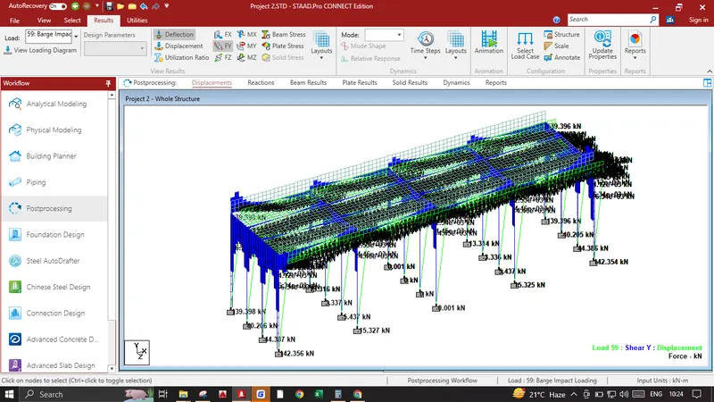
- 1. Click on Load Cases Details Click add write name Barge Impact Loading click add again click add select Member Load , under member load select uniform force and input the values mentioned in the image below.click add
- Select the Left Main Girder and assign it to the selected geometry.
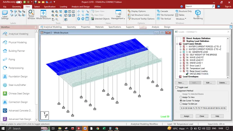
Analysis & Results :
- 1. Click on analysis and design click on define commands click add which adds a command for perform analysis, press run analysis, again go to post processing
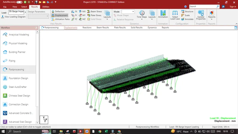
In Results Tab Displacement Pattern show in the image below for Different Load Cases mentioned at the top left tab.
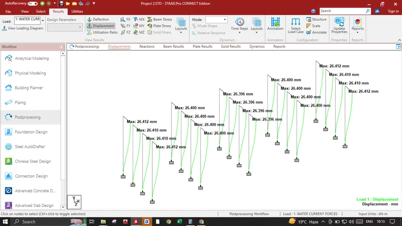
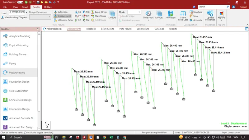
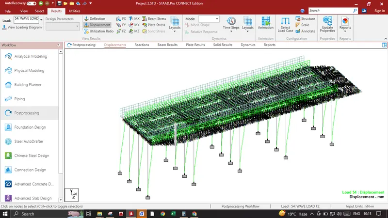
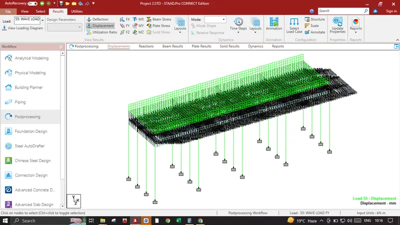
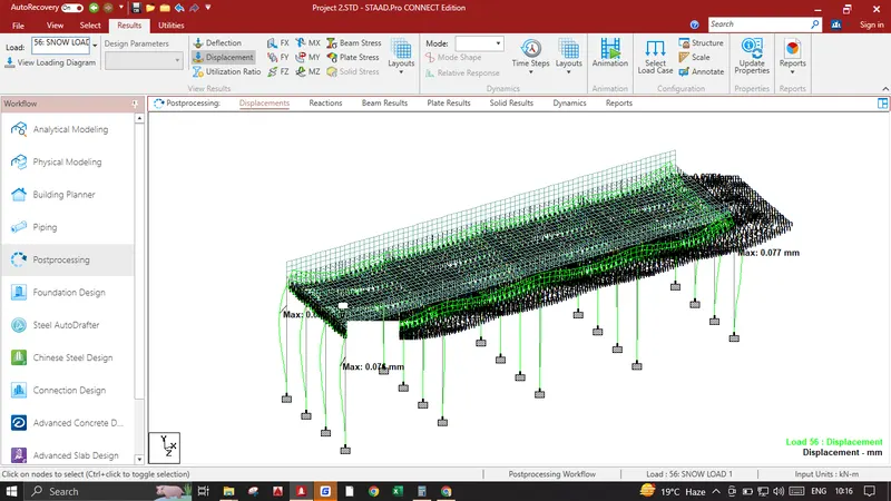
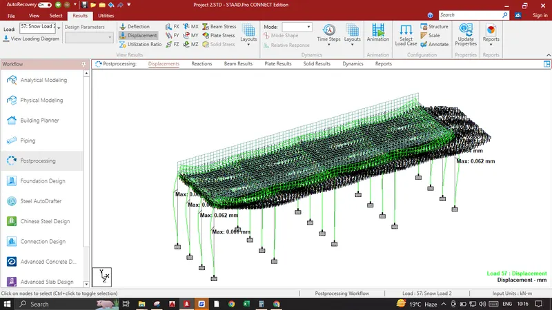
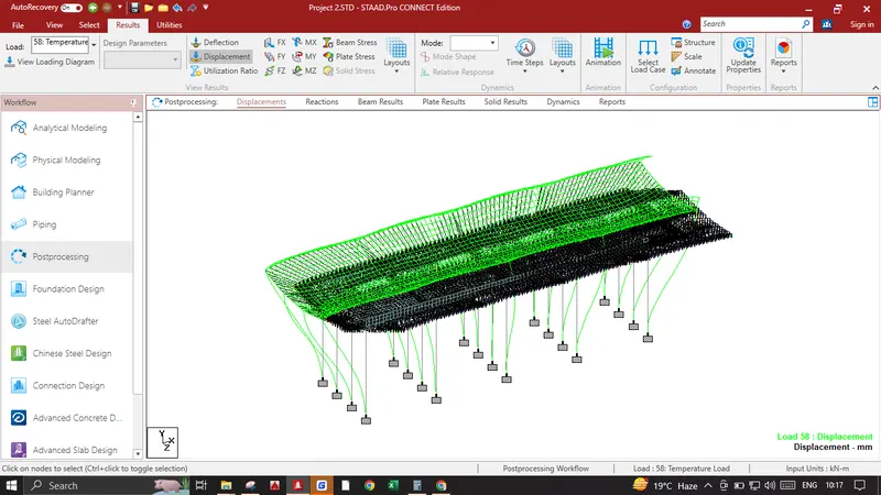
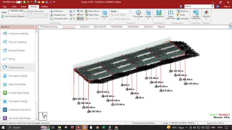
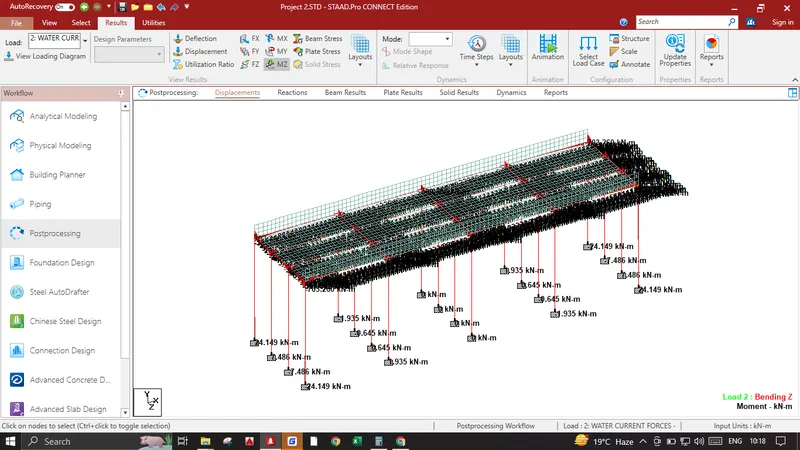
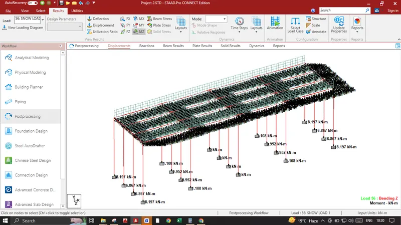
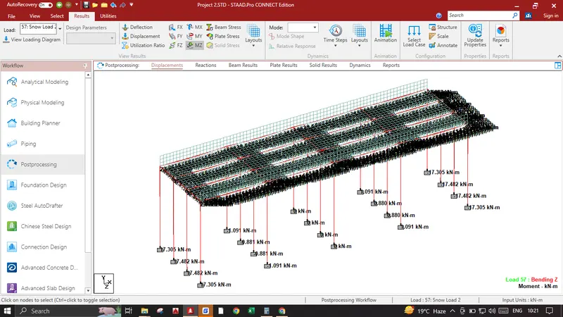
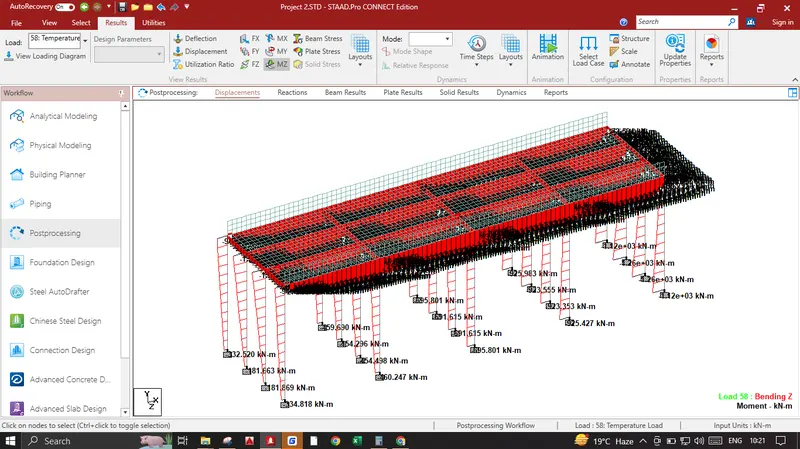
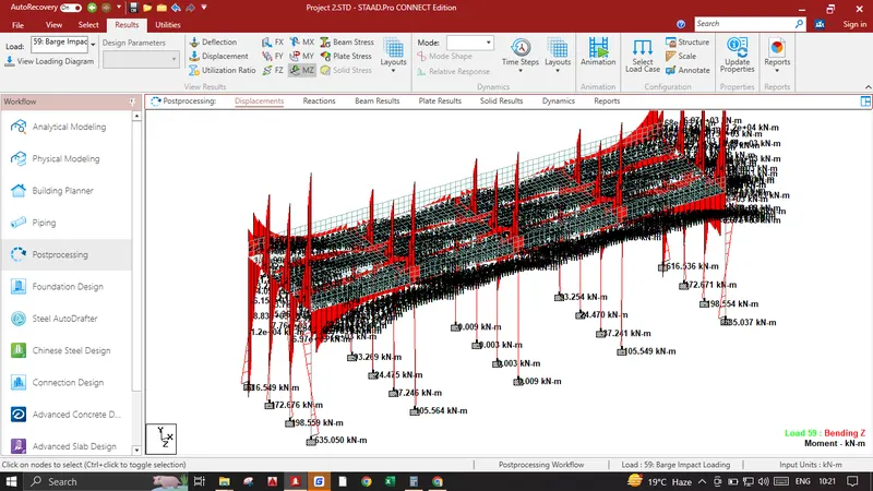
In Results Bending Moments shown in the image below for Different Load Cases mentioned at the top left tab.
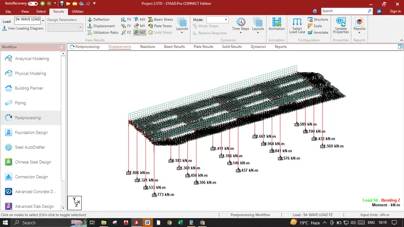
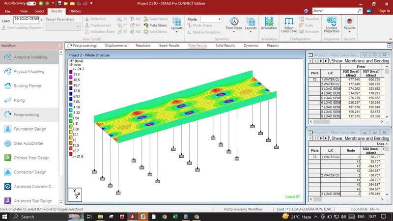
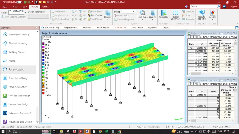
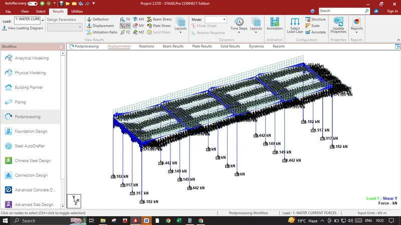
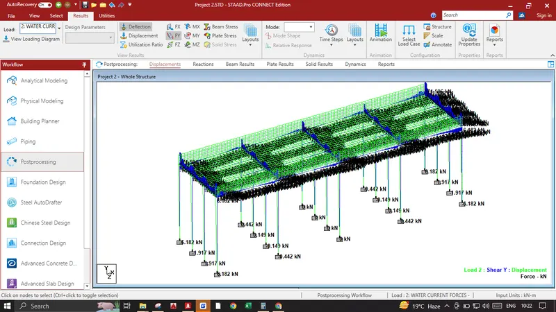
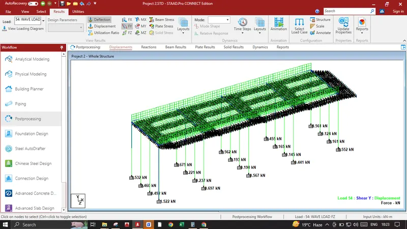
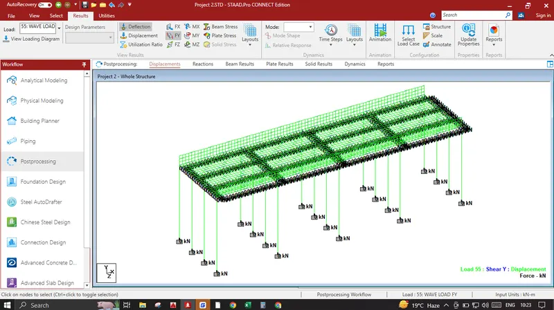
In Results Shear Stresses are shown in the image below
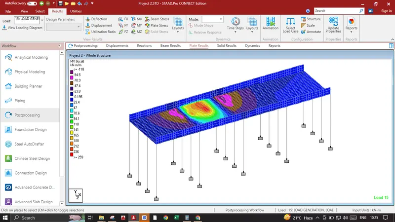
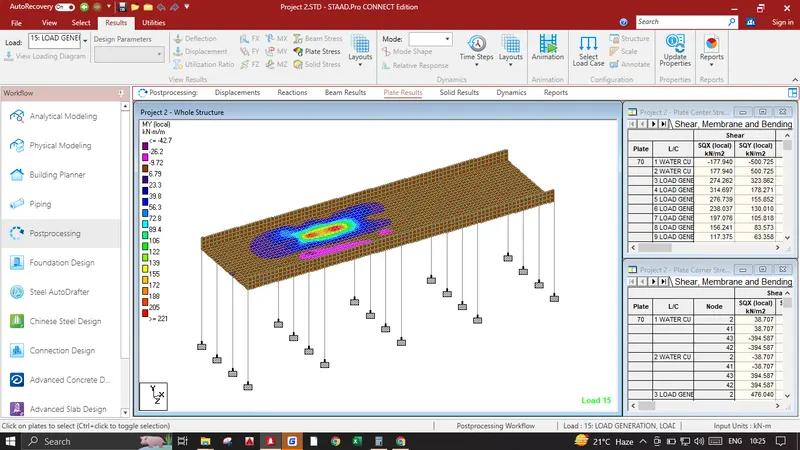
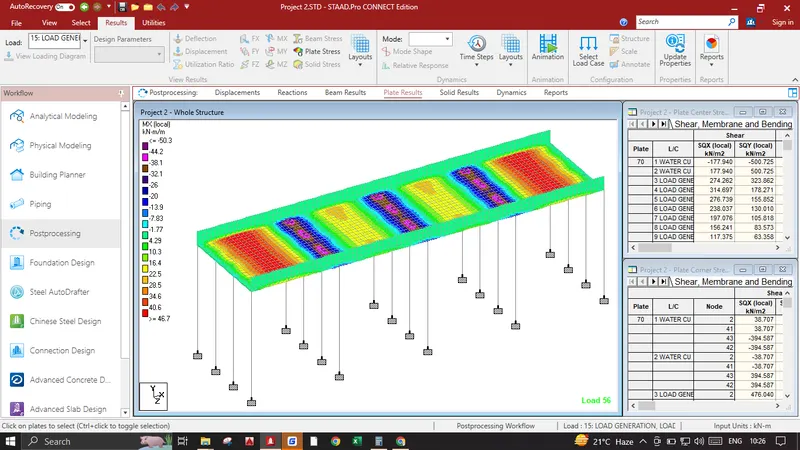
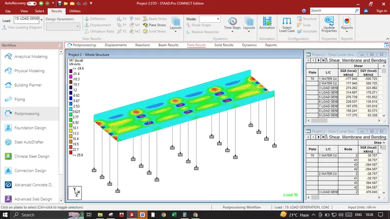
In Results Plate Stresses are shown in the image below