Project 2
WIRING HARNESS DESIGN OF BACKDOOR
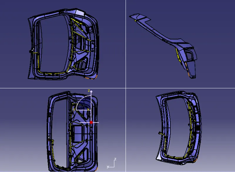
AIM- To Route the Wiring harness on the Given car body Backdoor and prepare the flatten view drawing in CATIA V5.
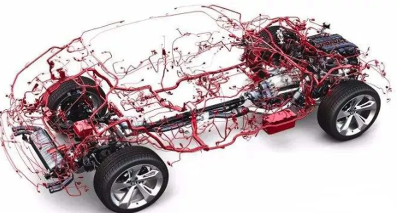
OBJECTIVE- The objective of this project is to route the wiring harness and prepare flatten view drawing for the Backdoor of the car. All types of packaging rules have to be considered while routing the harness and industry-based practices shall be demonstrated in harness design. All necessary details like clearance, clipping/clamping selection, harness fixing requirements, harness continuity should be provided in order to design the wiring harness.
BACKDOOR WIRING HARNESS
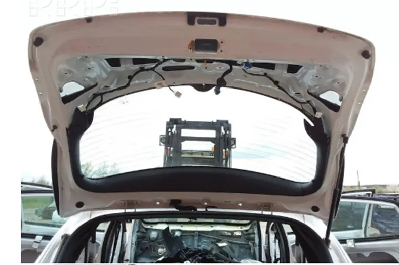
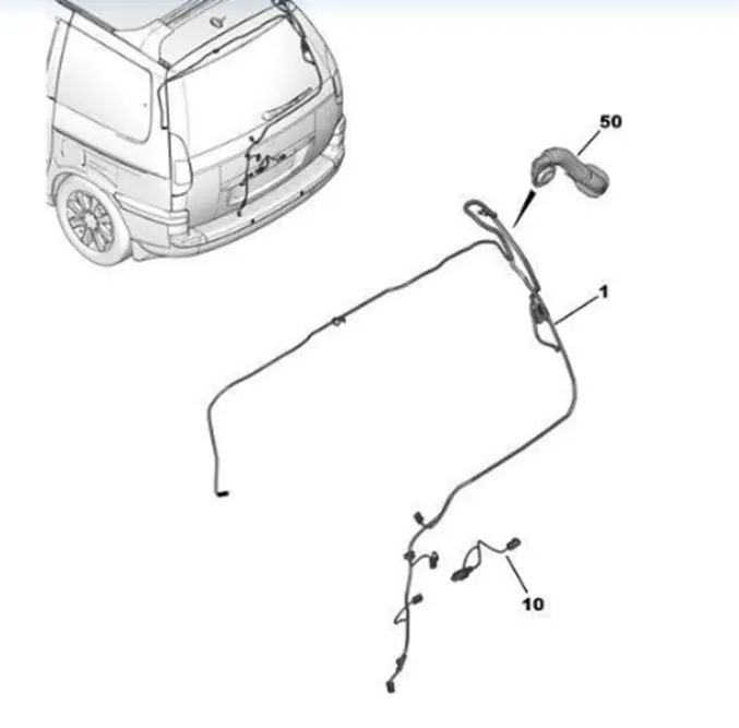
In the case of car doors, as the door of the automobiles opens and closes, the wires bend. If you use the car every day, the door will open and close many times. In case of Back door, the trunk could be open and close many times in daily life. Backdoor wiring harness mainly introduced to connect the brake lights, number plate lights, rear wiper motor, defogger connections. The harness routing should be maintained properly with all the supporting components like clips, clamps with proper protective covers, rubber grommets.
Rules Followed while Routing-
- Provide clips/clamps as per requirement.
- Make sure that there is no any fouling case while designing the wire harness. Additional clips/clamps may be used to avoid fouling case.
- Give additional slack if needed. 5-10% slack is sufficient. Provide additional slack if needed according to the surrounding and harness bending requirement. If harness is passing through the closures/doors or tail gates then envelope dimensions during opening and closing of doors shall be considered to provide the slack. Check the harness slack requirements with open and close conditions to avoid excess slack.
4.Enough Clips Clamps shall be provided to ensure positive clearance with surroundings and safety of wiring harness.
Fir tree clips and other clips can be added to the geometrical bundle as they are electrically defined and are part of the wire harness routing and should be provided with the wire bundle package.
- Avoid routing on sharp edges or else provide protection over the harness.
- Follow the clearance distance and keep away the harness from heat generation components.
- Protection should be provided as needed according to surrounding temperature.
- Routing through small structural holes and openings shall be avoided. To minimize chaffing and handling of the wiring harness during installation.
- Branch length should be greater than 50mm.the no of branch from a single branch point to 4.
- Minimum distance between two branch points should be at least 50mm.
- Minimum distance between clip and branch point should be at least 25mm.
- The wiring harness should be easy to assemble and easy to access.
ASSUMPTIONS –
- We have to route the wiring harness for two tail light and two number plate, and connect them main electrical system of as car.
- For two tail light and two number plate light we are using DEUSTCH 2 pole connector (DT06-2s).
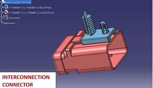
- A car body also have an interconnection connector which connects from a car body hatch to the, a car body wiring harness and is used a preferred location from where the routing for these lights starts.
- We will use 12 pole electrical connector with a mounting clip as an interconnection connector.
- As for the mounting parts clips/clamps which are used where ever necessary, HEllerman mounting clip and fixing clips are used.
- This car BIW body requires a lot of mounting hole provision for the clips, it should be discussed with BIW design team and should be asked for these extra features and it will be finalized by the BIW design team.
DESIGN METHODOLOGY –
STEP1- Download the backdoor cad data from given our website.
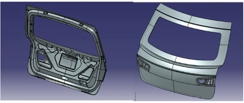
STEP2- Defining all the connector cad data clips and clamps as required for routing the backdoor.
Here we will use 2 pole connector and 12 pole connector which is required for the routing.
Choosing right components for the wire harness routing. Here we are using the components for backdoor upper and lower lights, wiper motor, sensors, and defogging equipment. The connectors used are first electrically defined and then added to the Catia model.
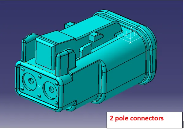
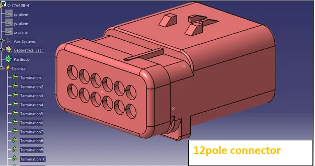
STEP 3- Defining clip as support.
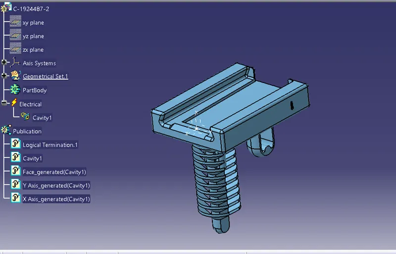
- We will use mounting clip for the mounting purpose.
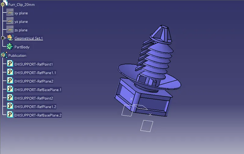
- We have to define geometrical parameters, bundle entry points and exit points from both left and right side of the clip.
- We have defined these clips electrically as a support in electrical part design workbench.
We need to mount the Fir tree clips on the Backdoor to provide support so we must first define it electrically with geometrical parameters, entry, and exit points on both the left and right sides of the clips.
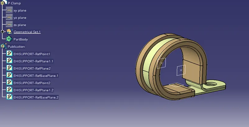
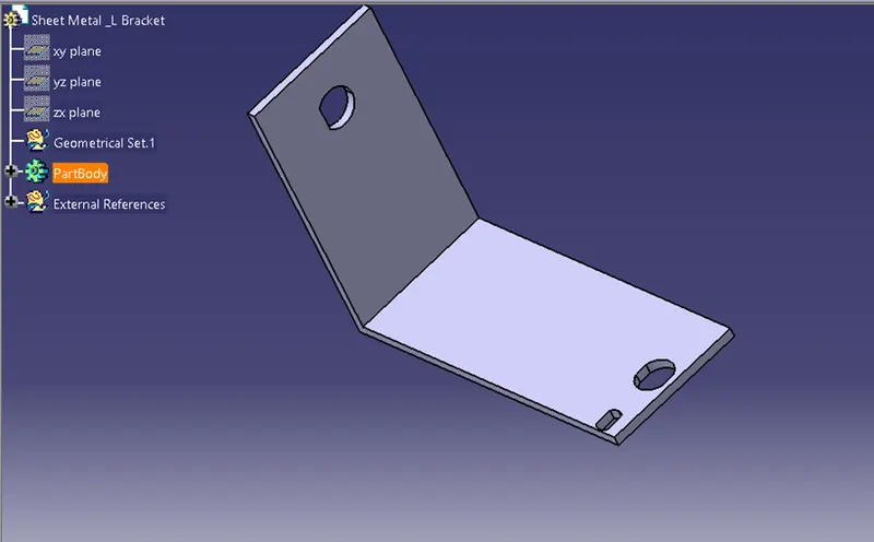
Provide L clip for mount interconnection connector.
STEP 4- creating context assembly with a new product file for the tail gate of the car as main assembly.
The context assembly contains the all 3D data for the backdoor car backdoor geometrical bundle.
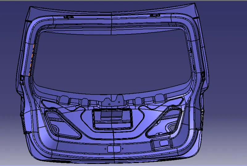
STEP 5- Adding all the connector clips, clamps in required position.
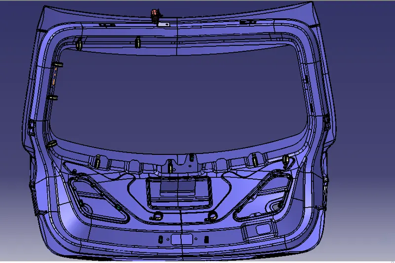
STEP 5- ROUTING THE WIRING HARNESS
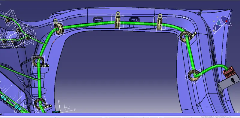
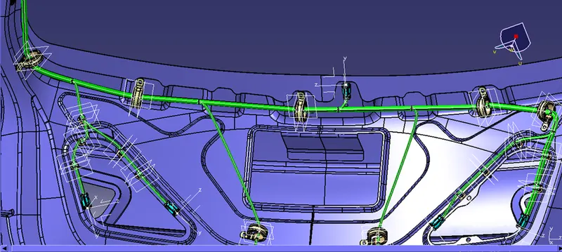
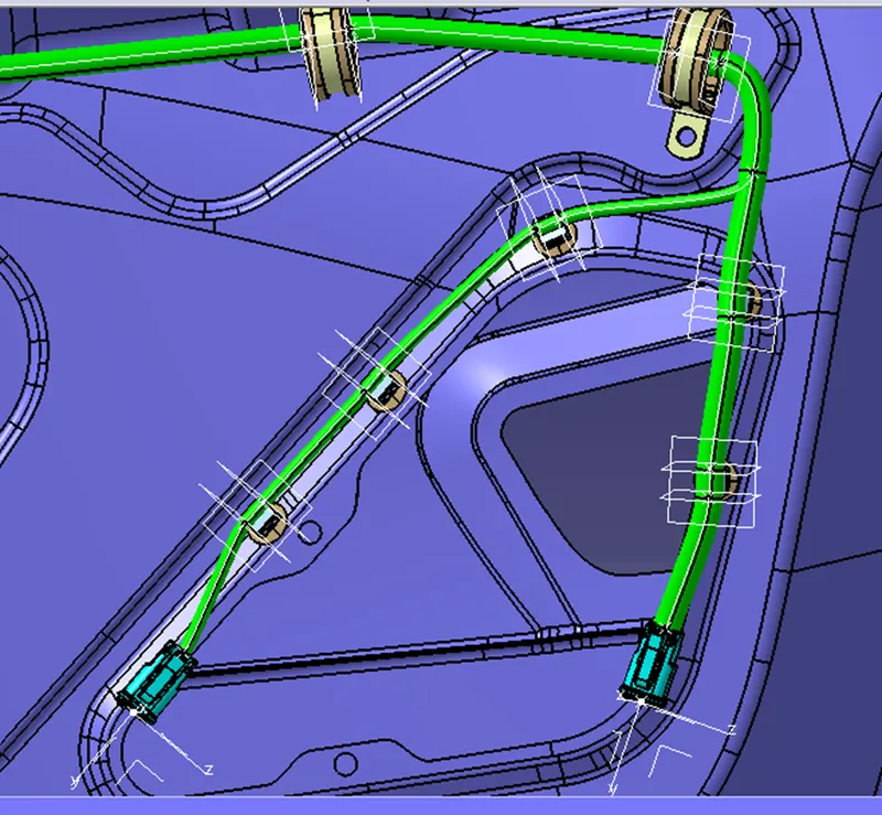
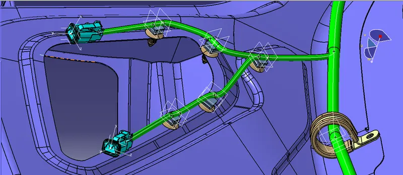
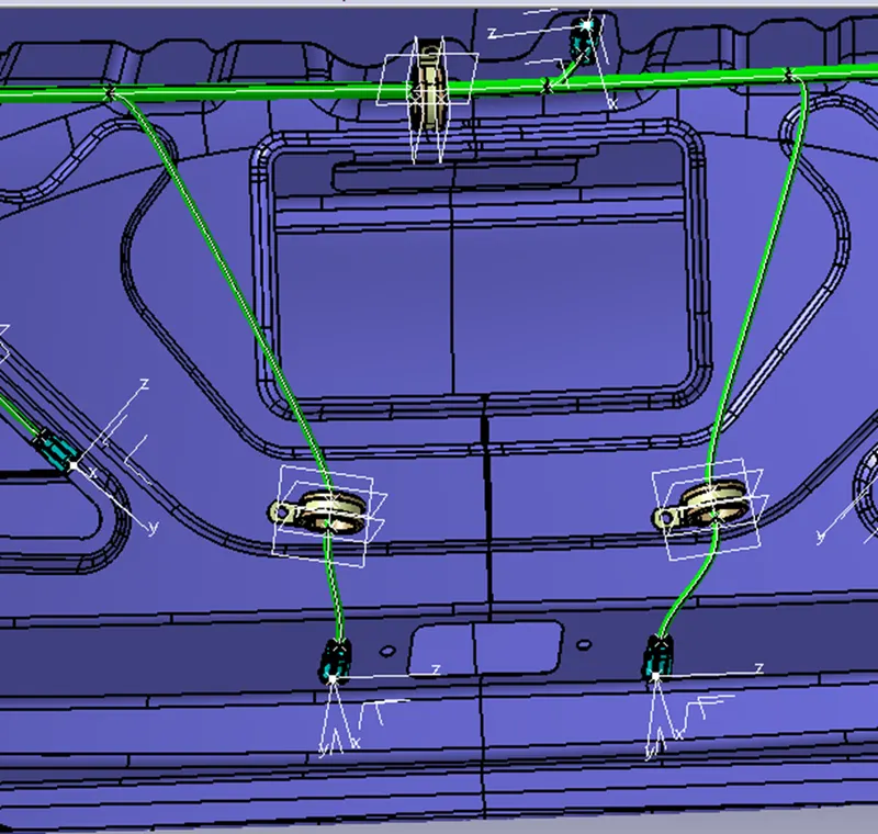
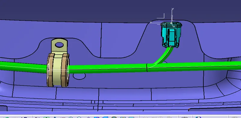
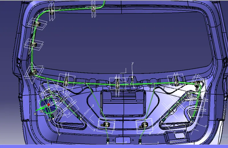
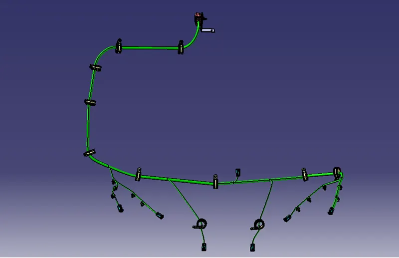
Adding all the connector, clips and clamps as required position with the help of manipulation tool, and using of compass. All the clamps and fir tree clips are positioned.
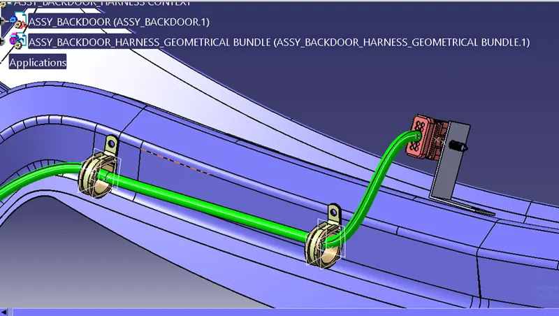
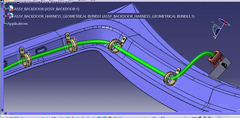
STEP 6- CHECK THE BUNDLE CONTINUITY
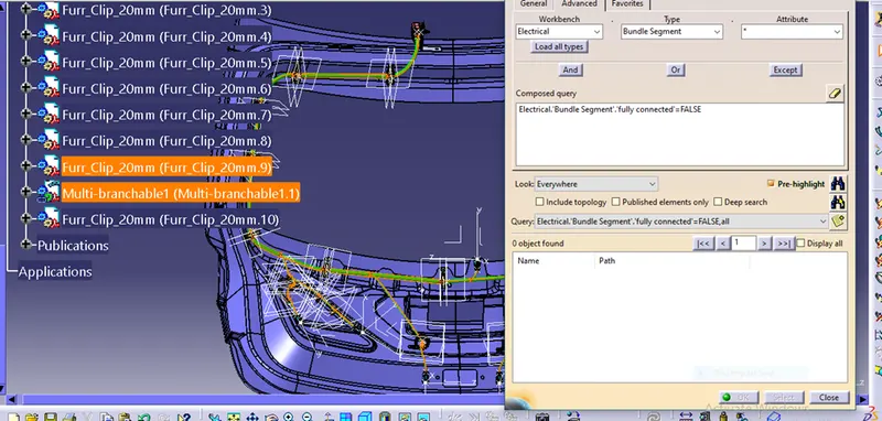
In this step, first we have to make sure that multi-branch able is selected then we have to go in Edit>Search>Advanced>Workbench-Electrical Type-Bundle Segment>Attribute-Fully Connected
By selecting True’ option will show all the connected bundle segments while selecting.
False’ option will show all the non-connected bundle segments.
Here, we have selected for the False option and searched for results. No bundle segments are highlighted found showing that means all the bundle segments are electrically connected.
STEP 7- Adding Protection Covering
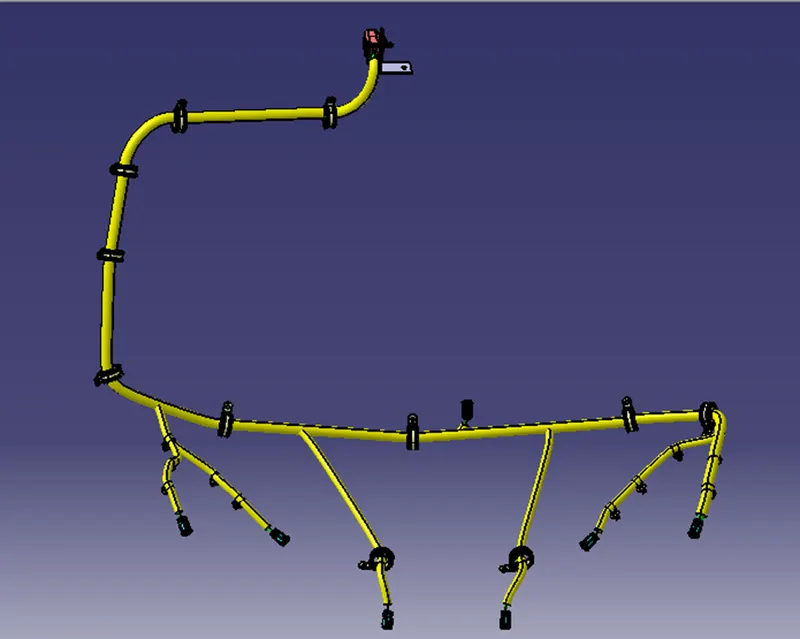
By using protection covering tool we protect all the bundle. We have created a catalogue and we add the protection cover of 15mm diameter and 10 mm diameter. Here we Create a gap from the end and start extremity.
STEP 8- CREATE FLATTEN VIEW
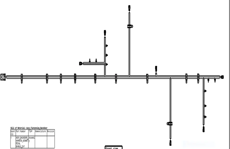
Now we open a new product file for the Electrical harness Flattening. Here we save the already made geometrical bundle segment and we extract the geometrical bundle to flatten harness by apply flattening parameters we flatten the geometrical bundle.
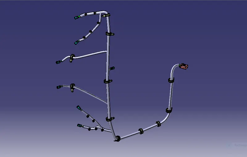
once the branches are flattened, we do some modification in the branches using the Rotate, bend, straighten etc. tools in the Electrical harness flattening.
STEP 9- CREATE A FLATTEN VIEW DRAWING
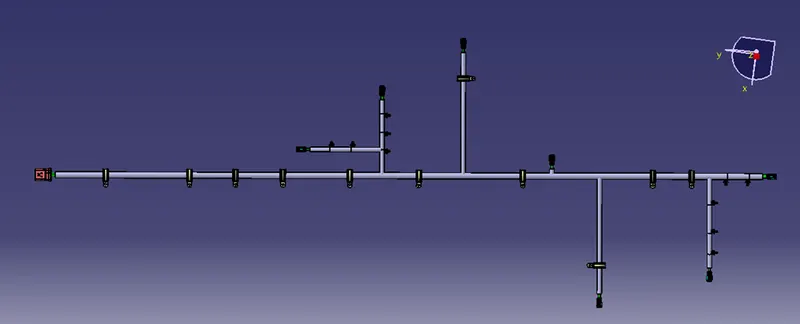
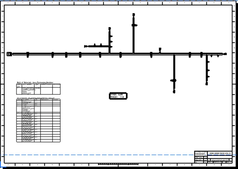
Now we're creating a new drawing file and defining all of the required drawing parameters. The front view of the Backdoor wire Harness Flattening Product file must be inserted into the Drawing file. It should be noted that the 3D wireframe is always ON in the 'Dress up settings. If this option is not enabled, the bundle segments will not be visible in the drawing view. the Backdoor wire Harness Flattens view's final Drawing view.
Before creating flatten view, first we have to define flattening parameters. Make sure that selecting ‘Single line’ for bundle segment and Double line for protective covering.
CONCLUSION-Routing of the wiring harness for the tail gate assembly has done and prepared flatten view drawing in Catia v5. Applied all the packaging rules while routing the wiring harness, implemented industry best practices in the harness design. Also provide details like clearance, clipping, selection, harness fixing requirements, harness continuity in order to design the harness.