Project 2
Aim:
Using MATLAB/simulink and the drive cycle from the attached excel sheet, find-
- The max heat generation of the battery
- The SOC of the battery at 2 *104second of the battery operation
| Time | Time Step | Battery Current |
| 00:00.4 | 0.1 | -0.9632 |
| 00:00.5 | 0.2 | -0.952 |
| 00:00.6 | 0.3 | -0.9072 |
| 00:00.7 | 0.4 | -0.9632 |
| 00:00.8 | 0.5 | -1.0304 |
| 00:00.9 | 0.6 | -0.9632 |
| 00:01.0 | 0.7 | -1.0304 |
| 00:01.1 | 0.8 | -1.008 |
| 00:01.2 | 0.9 | -0.9856 |
| 00:01.3 | 1 | -0.9632 |
| 00:01.4 | 1.1 | -0.9184 |
| 00:01.5 | 1.2 | -0.9296 |
| 00:01.6 | 1.3 | -0.9296 |
| 00:01.7 | 1.4 | -0.9296 |
| 00:01.8 | 1.5 | -0.9184 |
| 00:01.9 | 1.6 | -0.9408 |
| 00:02.0 | 1.7 | -0.896 |
| 00:02.1 | 1.8 | -0.9072 |
| 00:02.2 | 1.9 | -0.9072 |
| 00:02.3 | 2 | -0.9408 |
| 00:02.4 | 2.1 | -0.9296 |
| 00:02.5 | 2.2 | -0.9296 |
| 00:02.6 | 2.3 | -0.9968 |
| 00:02.7 | 2.4 | -0.9968 |
| 00:02.8 | 2.5 | -0.9408 |
| 00:02.9 | 2.6 | -0.9408 |
| Battery resistance | 2 milli ohm |
Consider the battery resistance is 0.5 mOhm, delta time is 0.1 and entropic factor is 2
1.The max heat generation of the battery
Max.heat generated = I^2 * R * T
= 0.896^2 * 0.5 * 120
= 48.1 J
Total heat generated = Joules heat + 2
= 48.1 + 2
= 50.1 J
2.The SOC of the battery at 2 *104second of the battery operation
Simulink model:
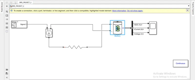
Signal block is the input to this soure.
Signal block is connected to controlld current source.
Controlled current source possitive is connected to the positive resistance.
Negative resistance is connected to the possitive of the battery.
Negative of current controlled source is connected to the battery negative.
Battery output is connected to the bus selector and it is connected to the scope.
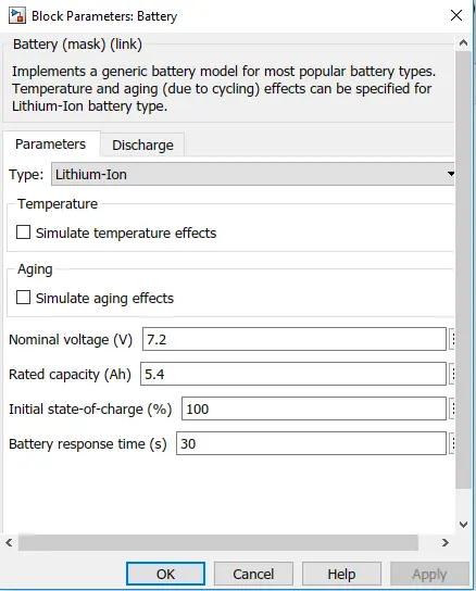
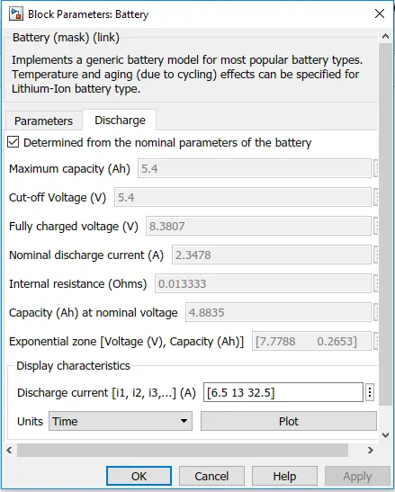
Battery :
Parameters:
Discharge:
Graph output:
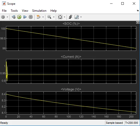
As given run time is for 208 seconds.
State of charge is decreased by 1%.
Current increase and decrease for 3 seconds and remains constant.
Voltage decreases from 8.4 to 8.1.