Project
AIM : To carryout a system level simulation of all-terrain vehicle.
Here in the question one term is used 'ALl-terrain Vehicle'. So before solving out the question we first need to understand this term thoroughly to get the better idea regarding the same.
All-terrain Vehicle :
A small motor vehicle with three or four wheels that is designed for use on various types of terrain is called as All-terrain Vehicle.
It is also known as a quad or quadricycle type vehicle. An All-Terrain motor vehicle could have three, four, or even six wheels. Unlike a motorcycle, generally, ATVs have more than two wheels. This vehicle runs on low-pressure tires. However, it has handlebars instead of a wheel for controlling the steering.
As the name indicates, manufacturers design an ATV to handle a wider variety of terrain than regular vehicles. In some countries, it is a street-legal motor vehicle and licensed for use on public roads. However, it is not street-legal or roadworthy within some countries’ states, territories, and provinces.
The riders ride an All Terrain Vehicle by sitting on it just like a motorcycle. However, you don’t need much effort to balance it because extra wheels give more stability at slower speeds. Also, people consider most dirt bikes ATVs because manufacturers only designed them for off-road use. Generally, most ATVs come with three or four wheels. However, some specialized applications require six-wheel models. Engine sizes of ATVs range from as low as 49cc to 1,000cc. However, the size of the engine depends upon the application.
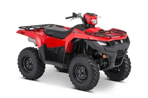
Now lets us switch to the model shared in the question of Baja ATV.
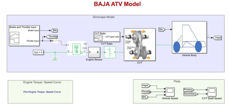
Here in this model the vehicle power transmission is done by using the CVT (Continuously Variable Transmission) instead of an automated gear box. So it would be essential to understand about CVT in a bit detail.
CVT (Continuously Variable Transmission) :
CVT is one of the widely used transmission which uses two pulleys of variable diameter which are connected by the belt. Here driver pully is driven by the engine & driven pully is connected with the driver pully & transfers the power to the differential to run the wheels.
So this transmission provides infinite gear ratios between the minimum & maximum values of speed. This is an automatic, single-speed & gearless transmission which has the ability to shift seamlessly, provides good fuel economy & plush ride.
Now lets move towards the analysis of share Baja ATV model.
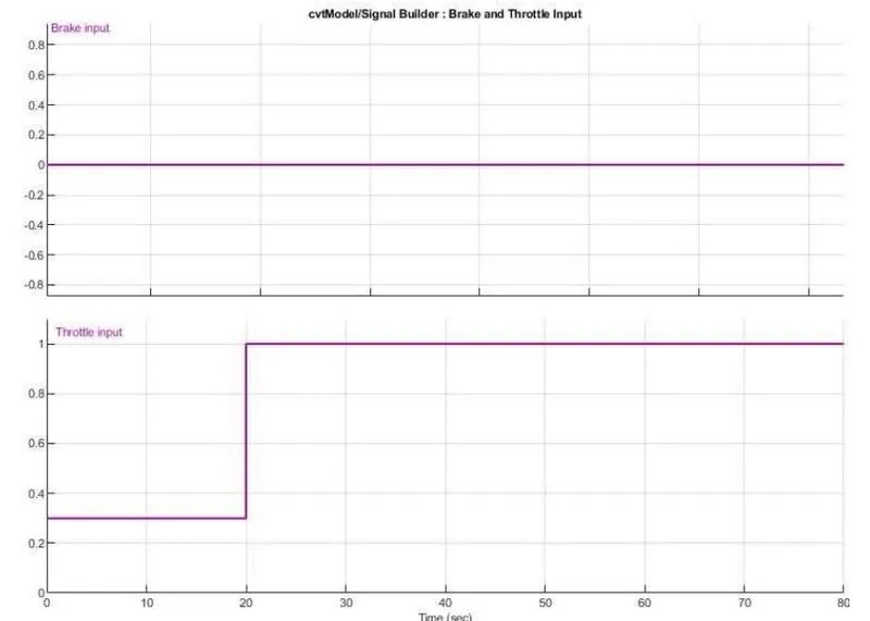
In this model the signal builder is connected with the brake & throttle & then to the Generic Engine. The brake & throttle value in the first brake input is zero & throttle input to the first 20 sec to 0.3 input & next 60 sec 1 apply.
The figure of signal builder is given below.
The next it is connected to the generic engine T. The throttle input signal T lies between zero & one & specifies the torque demanded from the engine as a fraction of the maximum possible torque.
Connections F & B are mechanical rotational conserving ports associated with the engine crankshaft & engine block respectively.
Connections P & FC are physical signal output ports through which engine power & fuel consumption rate are reported. Next B is connected in solver & mechanical rotational reference. The generic engine to F & then connected to the engine sensor.
The engine sensor input F sensing to the subsystem RPM sensing the device output of the scope.
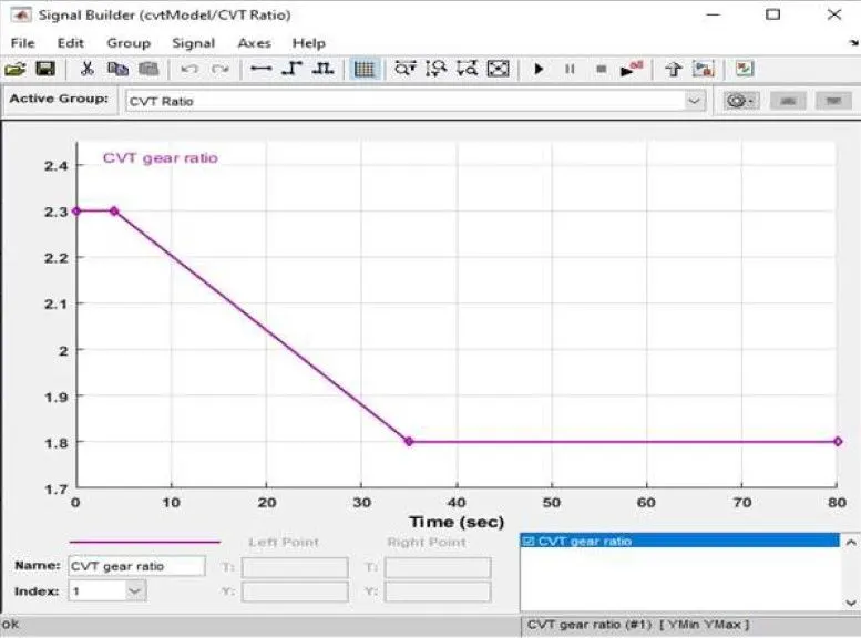
CVT Gear Ratio Input :
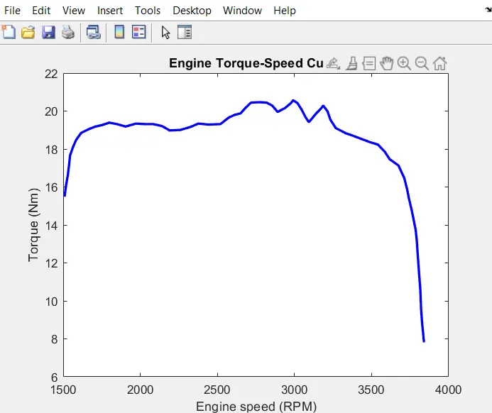
Torue vs Engine Input :
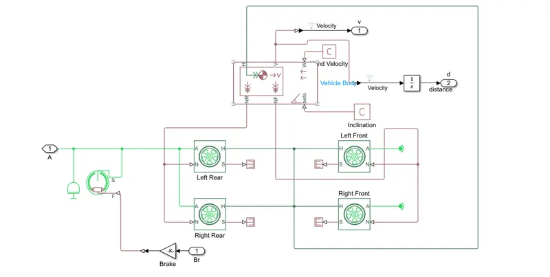
Vehicle Body :
Output for the case-1 (Simulink Model for BAJA ATV with CVT) :
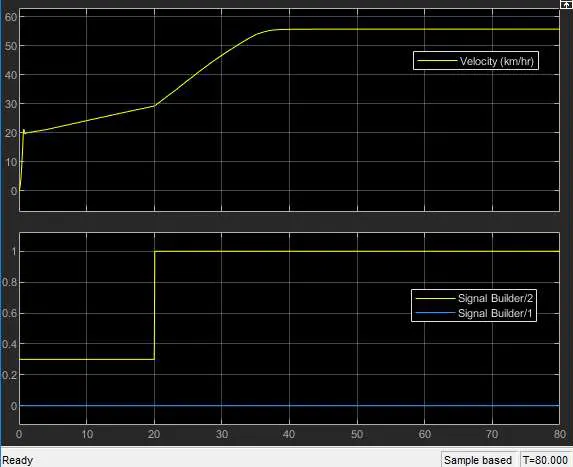
Here, it is clear from the graph that the vehicle attains its maximum speed (V= 55 km/hr) at full throttle = 1 after 30 seconds & then remains constant. The brake input value is zero, hence it has no effect on velocity.
CVT Shaft RPM :
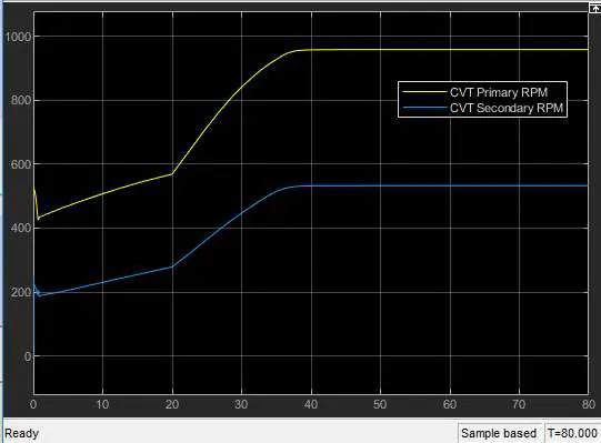
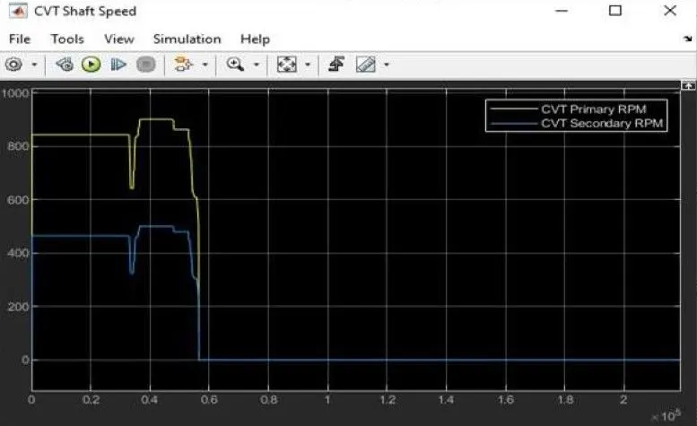
The above graphs shows the variation in the angular velocities of input & output shafts of the variable gear transmission system. These values differ with respect to the gear ratio.
Study for Case - 2 (Simukink model for BAJA ATV with CVT using Dashboard) :
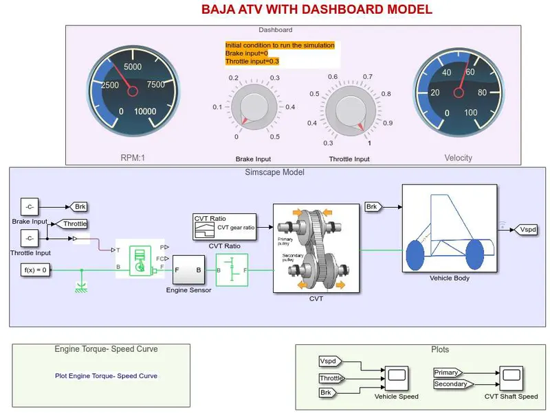
In the above given model we have a dashboard which contains knobs to control the inputs. In this case the inputs - Throttle & Break are not provided using the signal builder.
A knob is provided to control both the parameters in real-time for the user.
Ouptut for the Case-2 :
Vehicle Speed :
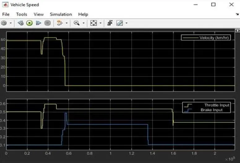
It can be observed from the graph that the velocity of the vehicle increases drastically from 0 to 50 kmph when throttle value is 0.5 & brake input is 0. Once the braking value increases from 0.1 to 0.5, the velocity of the vehicle decreases to 0 at constant throttle value. This explains the direct relation of vehicle velocity with respect to throttle & brake inputs,
CVT Shaft RPM :
Conclusion : By opting for both these method we have carried out a system level simulation of all terrain vehicle & plotted the graphs of the system.