System Level Simulation for an All Terrain Vehicle(BAJA ATV Challenge)
Aim: System Level simulaton of an all terrain vehicle.
Objective: To prepare a technical report on the ATV model explaining the model properties and results.
Theory:
A continuously variable transmission (CVT) is an automatic transmission that can change seamlessly through a continuous range of gear ratios. This contrasts with other transmissions that provide a limited number of gear ratios in fixed steps. The flexibility of a CVT with suitable control may allow the engine to operate at a constant RPM while the vehicle moves at varying speeds.
CVTs are used in automobiles, tractors, motor scooters, snowmobiles, and earthmoving equipment.
The most common type of CVT uses two pulleys connected by a belt or chain, however, several other designs have also been used at times.
Unlike traditional automatic transmissions, continuously variable transmissions don't have a gearbox with a set number of gears, which means they don't have interlocking toothed wheels. The most common type of CVT operates on an ingenious pulley system that allows an infinite variability between highest and lowest gears with no discrete steps or shifts.
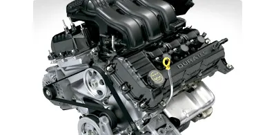 Photo courtesy Ford Motor Company Ford Freestyle Duratec engine with CVT |
Peer into a planetary automatic transmission, and you'll see a complex world of gears, brakes, clutches and governing devices. By comparison, a continuously variable transmission is a study in simplicity. Most CVTs only have three basic components:
- A high-power metal or rubber belt
- A variable-input "driving" pulley
- An output "driven" pulley
CVTs also have various microprocessors and sensors, but the three components described above are the key elements that enable the technology to work.
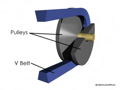 |
The variable-diameter pulleys are the heart of a CVT. Each pulley is made of two 20-degree cones facing each other. A belt rides in the groove between the two cones. V-belts are preferred if the belt is made of rubber. V-belts get their name from the fact that the belts bear a V-shaped cross section, which increases the frictional grip of the belt.
When the two cones of the pulley are far apart (when the diameter increases), the belt rides lower in the groove, and the radius of the belt loop going around the pulley gets smaller. When the cones are close together (when the diameter decreases), the belt rides higher in the groove, and the radius of the belt loop going around the pulley gets larger. CVTs may use hydraulic pressure, centrifugal force or spring tension to create the force necessary to adjust the pulley halves.
Variable-diameter pulleys must always come in pairs. One of the pulleys, known as the drive pulley (or driving pulley), is connected to the crankshaft of the engine. The driving pulley is also called the input pulley because it's where the energy from the engine enters the transmission. The second pulley is called the driven pulley because the first pulley is turning it. As an output pulley, the driven pulley transfers energy to the driveshaft.
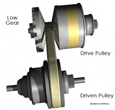 The distance between the center of the pulleys to where the belt makes contact in the groove is known as the pitch radius. When the pulleys are far apart, the belt rides lower and the pitch radius decreases. When the pulleys are close together, the belt rides higher and the pitch radius increases. The ratio of the pitch radius on the driving pulley to the pitch radius on the driven pulley determines the gear. |
When one pulley increases its radius, the other decreases its radius to keep the belt tight. As the two pulleys change their radii relative to one another, they create an infinite number of gear ratios -- from low to high and everything in between. For example, when the pitch radius is small on the driving pulley and large on the driven pulley, then the rotational speed of the driven pulley decreases, resulting in a lower “gear.” When the pitch radius is large on the driving pulley and small on the driven pulley, then the rotational speed of the driven pulley increases, resulting in a higher “gear.” Thus, in theory, a CVT has an infinite number of "gears" that it can run through at any time, at any engine or vehicle speed.
The simplicity and stepless nature of CVTs make them an ideal transmission for a variety of machines and devices, not just cars. CVTs have been used for years in power tools and drill presses. They've also been used in a variety of vehicles, including tractors, snowmobiles and motor scooters. In all of these applications, the transmissions have relied on high-density rubber belts, which can slip and stretch, thereby reducing their efficiency.
The introduction of new materials makes CVTs even more reliable and efficient. One of the most important advances has been the design and development of metal belts to connect the pulleys. These flexible belts are composed of several (typically nine or 12) thin bands of steel that hold together high-strength, bow-tie-shaped pieces of metal.
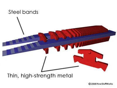 Metal belt design |
Metal belts don't slip and are highly durable, enabling CVTs to handle more engine torque. They are also quieter than rubber-belt-driven CVTs.
Simulink Model:
Case 1: ATV Model in Real time data using BAJA ATV Dashboard
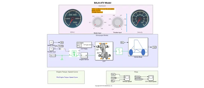
In this model, Brake input and throttle input are given by the user in the real time by the dashboard. This data is input to the Engine sensor and then to the CVT block. For, gear ratio, data is entered using a signal bulider.
CVT Input Gear Ratio:
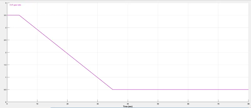
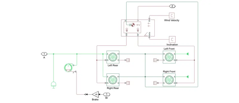
The data is then processed and then input to the vehicle body.
On the dashboard, two different knobs have been used, they can be used to variate the brake input and throttle. The data can be varied ib real time with the help of these knobs, so as to simulate the model in real world.
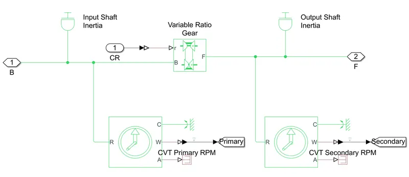
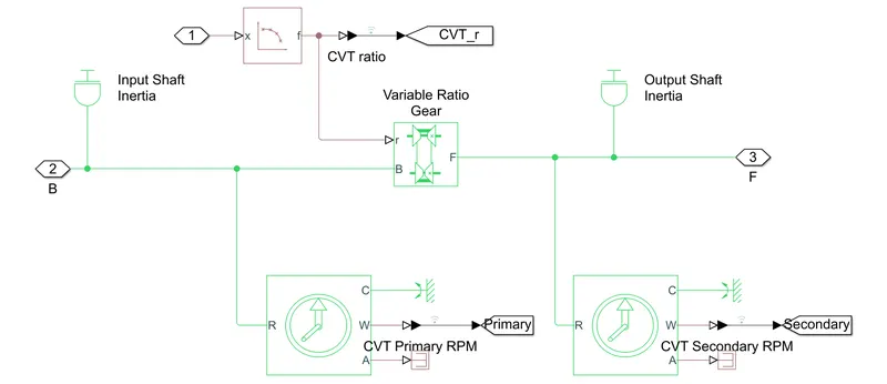
CVT Model: In the below model, two shafts have been used. These are the two shafts of the CVT(one for primary and the other for secondary). This is then connected to the Variable gear ratio and two sensors are used to sense the rotational movement of the shafts.
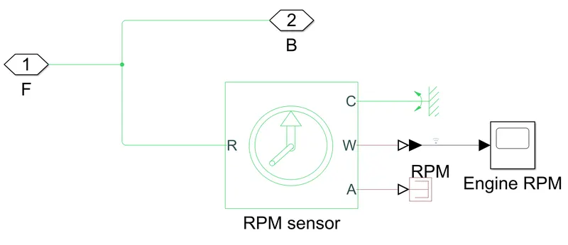
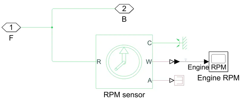
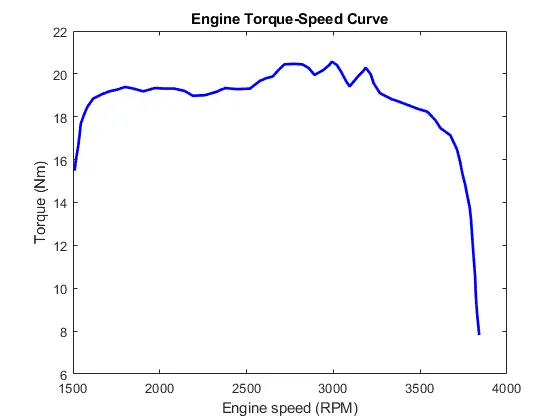
Engine Sensor: In this block, a generic engine data is entered. a sensor is used to record the RPM of the output shaft of the engine.
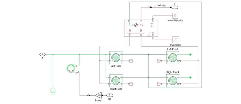
Vehicle Body:
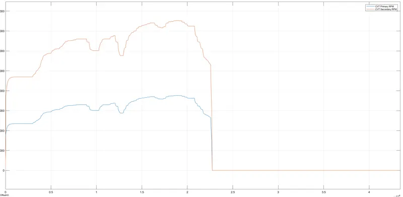
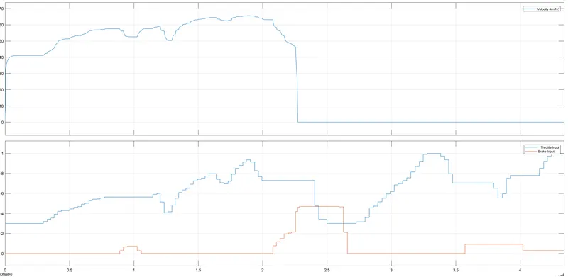
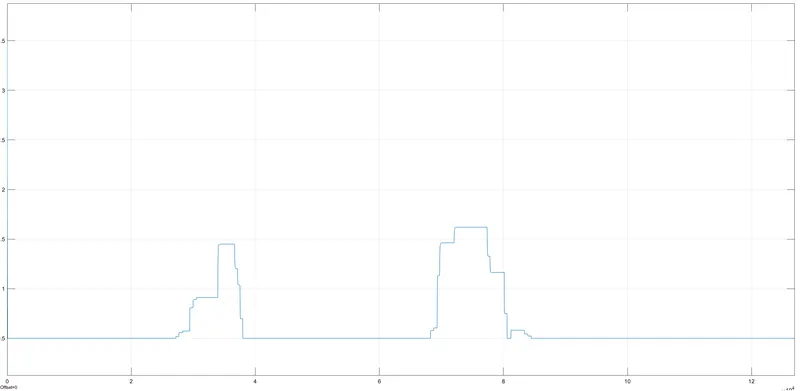
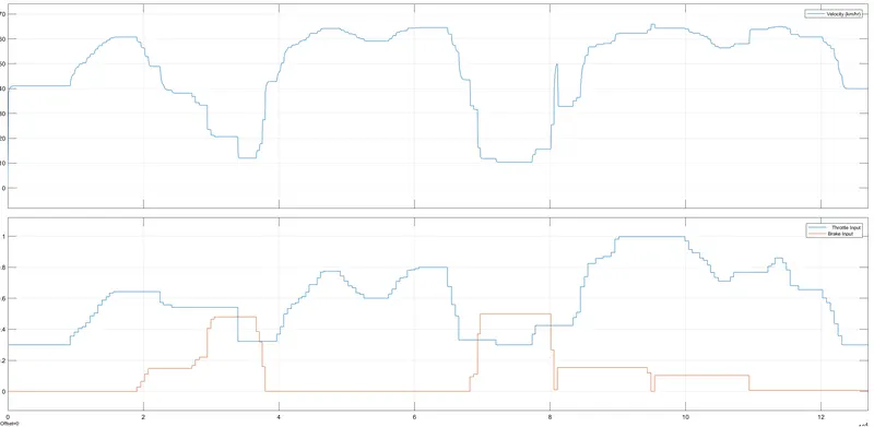
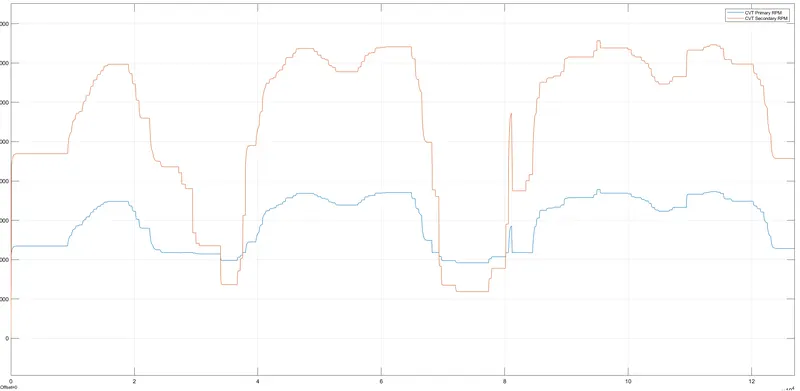
Results: In the below shown curves, it is quite clear that the Primary CVT RPM and Secondary RPM is more as the throttle is increased. Also, with the increased in the throttle value, the speed of the vehicle is also incresed, which is quite obvious.
Case 2: ATV Model in real time using lookup table:
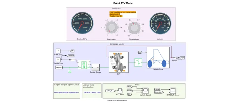
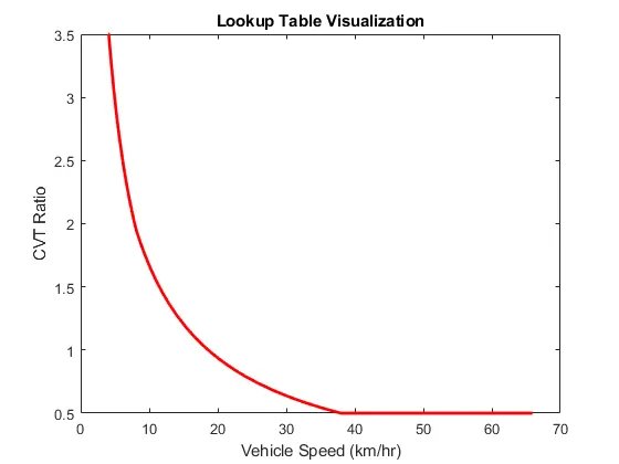
In this model, instead of giving input manually to the CVT, a feedback is gievn into the CVT because the gear ratio is affected by the vehicle velocity in real time. For that purpose a lookup table is used in the model(please see appendix to see the lookup table data visualization).
CVT Model:
Engine Model:
Vehicle Body:
Results:
Appendix:
Engine Speed Vs Torque:
Lookup Table Visualization:
References: