Project 1- Traffic Jam Assistant Feature
Aim: to develop the Traffic Jam Assist feature that can assist driving in highway traffic jams while the host vehicle automatically follows the vehicle ahead.
Objectives:
- Developing the Traffic Jam Assist feature as per the Requirement Document using MATLAB Simulink.
- To Follow all the MBD related processes: Requirement Tagging & Traceability, SLDD creation, Configuration Parameter changes, Model Advisor check & Code Generation.
- To Use Embedded Coder to generate the code.
Theory:
To help mitigate some of the fatigue associated with stop-and-go commuting, a growing number of automakers offer Traffic Jam Assist (TJA). This Level 2 advanced driving assistance system (ADAS) combines adaptive cruise control and lane-centering capabilities to ease the burden of getting through clogged highways and traffic congestion.
The latest forward-looking radar and camera technology helps sense traffic and the road ahead. Fused data from both sensors is used to help adapt the vehicle speed to the speed of the vehicle ahead, with Stop-and-Go functionality. Based on optical detection of lane markings, the vehicle is centered within the occupied lane.
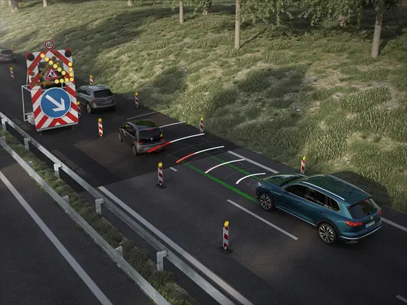
To help make heavy traffic more bearable, TJA essentially acts as a low-speed version of adaptive cruise control. It utilizes a front-mounted radar unit, cameras, and sensors to detect vehicles ahead and automatically adjust to their speeds. But as opposed to adaptive cruise control’s goal of maintaining highway cruising velocity, TJA takes effect when a car approaches slowed traffic and slows to a crawl.
Designed to operate at speeds under 40 miles per hour, TJA will adjust the vehicle’s following distance based on the stop-and-go traffic ahead. In other words, the driver does not have to operate the gas or brake pedals through heavy traffic actively. The TJA system will accelerate and decelerate the vehicle on its own without driver intervention.
TJA will also bring the vehicle to a complete stop and then resume driving when the traffic ahead moves. However, most TJA systems require that the driver re-engage the system with a light touch to the gas pedal if the car has been completely still for more than 30 seconds. This “reawakening” of the system helps ensure the driver is paying attention to the overall traffic conditions and not simply tuning out because the car has been resting for an extended time. In the same vein, most TJA systems disengage if the driver’s hands leave the wheel for too long.
In addition to managing speed, most TJA systems also utilize lane-centering technology to keep the vehicle from drifting. The system uses a camera to identify lane markings on the road surface and automatically provides subtle steering inputs and minor corrections to keep the car in the center of its lane. This functionality helps drivers who may lose alertness and begin drifting after long periods of slow-moving traffic.
A driver can make an intended lane change at any time while using TJA with regular steering input. This action will override the TJA system’s lane-centering functionality. Once the vehicle has made the lane change, the system will resume lane-centering by tracking the markings of the new lane. Some TJA systems may require re-engagement after the driver has taken control of the steering. All TJA systems allow for full driver override at any time in the event of an emergency.
Although TJA has many benefits, similar but more sophisticated systems exist, such as Hyundai Motor Group’s Highway Driving Assist (HDA) and Highway Driving Assist II (HDA2). These systems give Hyundai, Genesis, and Kia models a definitive edge over vehicles with TJA alone, employing navigation-based guidance.
Beyond HDA, automakers such as Audi and Honda, among others, are currently developing the next generation of TJA, which would arrive as a Level 3 autonomous vehicle system in the foreseeable future. With this technology, drivers will enjoy higher levels of safety, security, and stress reduction while traversing traffic on congested highways in a potentially hands-free manner.
Advantages
- Optional front corner radars help to improve detection of vehicles cutting in.
- The driver is required to monitor both surrounding traffic and system status and can override the system at anytime (SAE level 2 automation).
- Traffic Jam Assist’s longitudinal, Stop-and-Go control function can manage vehicle speed and help maintain safe distance to the leading vehicle; actuation is performed electronicaly controlled braking systems or integrated brake control in the case of vacuum-less braking systems.
- The lateral control function can help maintain vehicle position in the lane; actuation is performed by ZF’s well-established, high-bandwidth belt drive or column drive electric powered steering products
- Helps dramatically reduce the efforts and stress of highway driving in congested traffic
- Helps enhance vehicle and occupant safety
- Supports collision mitigation or even collision avoidance to help improve road safety
Input Signals:
|
Name of the Signal |
Data Type |
Range |
|
Input_Voltage |
uint8 |
0 - 255 |
|
Input_Switch |
boolean |
0 – 1 |
|
Enable_Display |
uint8 |
0 - 255 |
Output Signal:
|
Name of the Signal |
Data Type |
Range |
|
Output_Display |
uint8 |
0 - 255 |
Calibration Signals:
|
Name of the Signal |
Data Type |
Range |
Initial Value |
|
VOLTAGE_MINIMUM_RANGE |
uint8 |
0 – 255 |
30 |
|
VOLTAGE_MAXIMUM_RANGE |
uint8 |
0 – 255 |
50 |
|
OFF_MODE |
uint8 |
0 – 255 |
2 |
|
ON_MODE |
uint8 |
0 – 255 |
1 |
|
STANDBY_MODE |
uint8 |
0 – 255 |
3 |
|
INTERRUPT_1 |
boolean |
0 – 1 |
1 |
|
INTERRUPT_2 |
boolean |
0 - 1 |
1 |
|
NO_DISPLAY |
uint8 |
0 – 255 |
0 |
Local Signal:
|
Name of the Signal |
Data Type |
Range |
|
Optimum_Voltage |
boolean |
0 - 1 |
Requirement No 1:
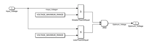
- Input Signal “Input_Voltage” is compared against voltage values “VOLTAGE_MINIMUM_RANGE” & “VOLTAGE_MAXIMUM_RANGE”.
- Incoming input signal “Input_Voltage” must be greater than – equal to “VOLTAGE_MINIMUM_RANGE” and less than – equal to “VOLTAGE_MAXIMUM_RANGE”.
- Output signal from here is “Optimum_Voltage” which will be one of the inputs to the subsystem “DisplayUnit”.
Requirement No 2 (DisplayUnit Subsystem):
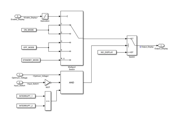
- Input Signals are “Optimum_Voltage”, “Input_Switch”,“Enable_Display”. Signal “Enable_Display” must be saturated between the range 0 – 7. Output signal from the subsystem is “Output_Display”.
- Input Signal “Enable_Display” is compared against pre – defined set of values in a multiport switch. Total data ports in the multiport switch is 5.
- Multiport switch inputs 1 & 2 is connected to calibration signal “ON_MODE”, Multiport switch inputs 3 & 4 is connected to calibration signal “OFF_MODE” while Multiport switch input 5 is connected to calibration signal “STANDBY_MODE”.
- The output from Multiport switch is connected to the first input port of the Switch block. The third input port of the Switch block is connected to the calibration signal “NO_DISPLAY”.
- Meanwhile NOT value of input signal “Input_Switch” is compared in an AND gate against input signal “Optimum_Voltage” and the output from comparing if calibration signals “INTERRUPT_1” & “INTERRUPT_2” are equal. The output of the AND gate is the second input of the switch block.
- The output from the switch block is “Output_Display”.
Procedure:
- The simulink model is designed in the matlab simulink using the suitable blocks
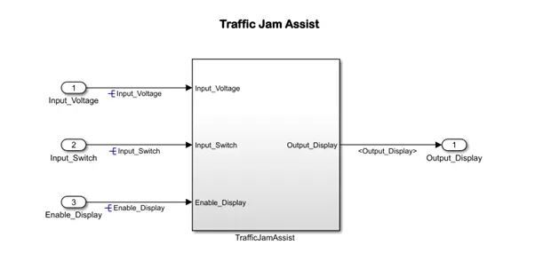
>>subsystem1
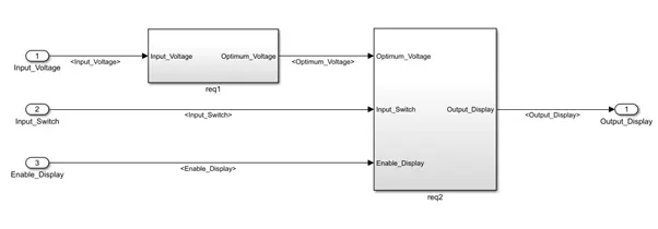
>>req1
>>Req2
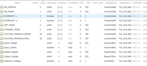
- The input,output and calibrated signals are defined in the Simulink libraby data directory file,all parameters are defined in the SLD file.
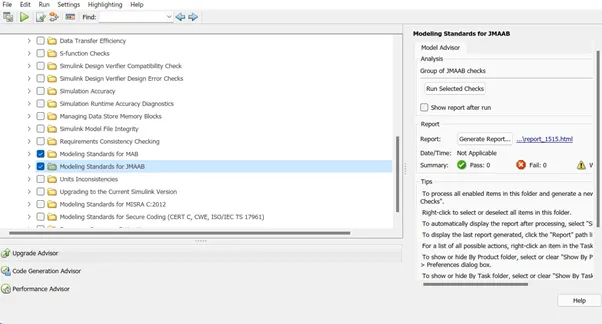
- Now we run model advisor checks on the model to see whether our model is MAB standard compliant and generate a report
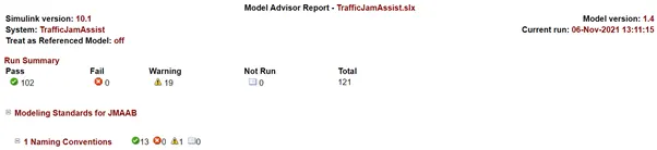
MA report:
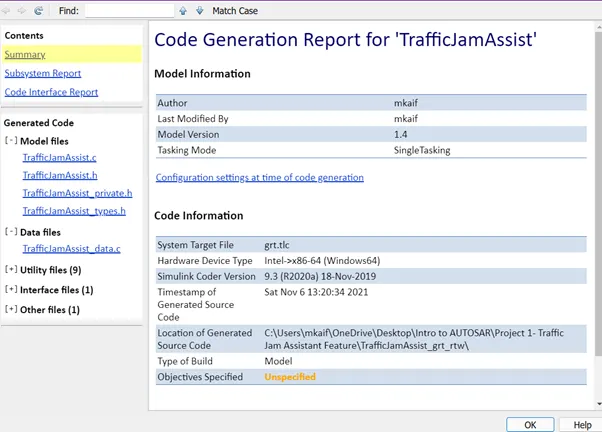
5.Now we generate the C code using the Embedded C code generator app
File: TrafficJamAssist.c
1	/*
2	* TrafficJamAssist.c
3	*
4	* Code generation for model "TrafficJamAssist".
5	*
6	* Model version : 1.4
7	* Simulink Coder version : 9.3 (R2020a) 18-Nov-2019
8	* C source code generated on : Sat Nov 6 13:20:34 2021
9	*
10	* Target selection: grt.tlc
11	* Note: GRT includes extra infrastructure and instrumentation for prototyping
12	* Embedded hardware selection: Intel->x86-64 (Windows64)
13	* Code generation objectives: Unspecified
14	* Validation result: Not run
15	*/
16
17	#include "TrafficJamAssist.h"
18	#include "TrafficJamAssist_private.h"
19
20	/* Block signals (default storage) */
21	B_TrafficJamAssist_T TrafficJamAssist_B;
22
23	/* External outputs (root outports fed by signals with default storage) */
24	ExtY_TrafficJamAssist_T TrafficJamAssist_Y;
25
26	/* Real-time model */
27	RT_MODEL_TrafficJamAssist_T TrafficJamAssist_M_;
28	RT_MODEL_TrafficJamAssist_T *const TrafficJamAssist_M = &TrafficJamAssist_M_;
29
30	/* Model step function */
31	void TrafficJamAssist_step(void)
32	{
33	uint8_T tmp;
34
35	/* Switch: '<S3>/Switch' incorporates:
36	* Constant: '<S2>/VOLTAGE_MAXIMUM_RANGE'
37	* Constant: '<S2>/VOLTAGE_MINIMUM_RANGE'
38	* Constant: '<S3>/Constant1'
39	* Constant: '<S3>/Constant3'
40	* Constant: '<S3>/Constant4'
41	* Inport: '<Root>/Input_Switch'
42	* Inport: '<Root>/Input_Voltage'
43	* Logic: '<S2>/AND'
44	* Logic: '<S3>/AND'
45	* Logic: '<S3>/NOT'
46	* RelationalOperator: '<S2>/GreaterThanOrEqual'
47	* RelationalOperator: '<S2>/LessThanOrEqual'
48	* RelationalOperator: '<S3>/Equal'
49	*/
50	if ((Input_Voltage >= TrafficJamAssist_P.VOLTAGE_MAXIMUM_RANGE) &&
51	(Input_Voltage <= TrafficJamAssist_P.VOLTAGE_MAXIMUM_RANGE) &&
52	(!Input_Switch) && (TrafficJamAssist_P.INTERRUPT_1 ==
53	TrafficJamAssist_P.INTERRUPT_2)) {
54	/* Saturate: '<S3>/Saturation' incorporates:
55	* Inport: '<Root>/Enable_Display'
56	*/
57	if (Enable_Display < 7) {
58	tmp = Enable_Display;
59	} else {
60	tmp = 7U;
61	}
62
63	/* End of Saturate: '<S3>/Saturation' */
64
65	/* MultiPortSwitch: '<S3>/Multiport Switch' incorporates:
66	* Constant: '<S3>/Constant2'
67	* Constant: '<S3>/OFF_MODE'
68	* Constant: '<S3>/ON_MODE'
69	*/
70	switch (tmp) {
71	case 1:
72	TrafficJamAssist_B.Output_Display = TrafficJamAssist_P.ON_MODE;
73	break;
74
75	case 2:
76	TrafficJamAssist_B.Output_Display = TrafficJamAssist_P.ON_MODE;
77	break;
78
79	case 3:
80	TrafficJamAssist_B.Output_Display = TrafficJamAssist_P.OFF_MODE;
81	break;
82
83	case 4:
84	TrafficJamAssist_B.Output_Display = TrafficJamAssist_P.OFF_MODE;
85	break;
86
87	default:
88	TrafficJamAssist_B.Output_Display = TrafficJamAssist_P.STANDBY_MODE;
89	break;
90	}
91
92	/* End of MultiPortSwitch: '<S3>/Multiport Switch' */
93	} else {
94	TrafficJamAssist_B.Output_Display = TrafficJamAssist_P.NO_DISPLAY;
95	}
96
97	/* End of Switch: '<S3>/Switch' */
98
99	/* Outport: '<Root>/Output_Display' */
100	TrafficJamAssist_Y.Output_Display = TrafficJamAssist_B.Output_Display;
101
102	/* Matfile logging */
103	rt_UpdateTXYLogVars(TrafficJamAssist_M->rtwLogInfo,
104	(&TrafficJamAssist_M->Timing.taskTime0));
105
106	/* signal main to stop simulation */
107	{ /* Sample time: [0.2s, 0.0s] */
108	if ((rtmGetTFinal(TrafficJamAssist_M)!=-1) &&
109	!((rtmGetTFinal(TrafficJamAssist_M)-TrafficJamAssist_M->Timing.taskTime0)
110	> TrafficJamAssist_M->Timing.taskTime0 * (DBL_EPSILON))) {
111	rtmSetErrorStatus(TrafficJamAssist_M, "Simulation finished");
112	}
113	}
114
115	/* Update absolute time for base rate */
116	/* The "clockTick0" counts the number of times the code of this task has
117	* been executed. The absolute time is the multiplication of "clockTick0"
118	* and "Timing.stepSize0". Size of "clockTick0" ensures timer will not
119	* overflow during the application lifespan selected.
120	* Timer of this task consists of two 32 bit unsigned integers.
121	* The two integers represent the low bits Timing.clockTick0 and the high bits
122	* Timing.clockTickH0. When the low bit overflows to 0, the high bits increment.
123	*/
124	if (!(++TrafficJamAssist_M->Timing.clockTick0)) {
125	++TrafficJamAssist_M->Timing.clockTickH0;
126	}
127
128	TrafficJamAssist_M->Timing.taskTime0 = TrafficJamAssist_M->Timing.clockTick0 *
129	TrafficJamAssist_M->Timing.stepSize0 +
130	TrafficJamAssist_M->Timing.clockTickH0 *
131	TrafficJamAssist_M->Timing.stepSize0 * 4294967296.0;
132	}
133
134	/* Model initialize function */
135	void TrafficJamAssist_initialize(void)
136	{
137	/* Registration code */
138
139	/* initialize non-finites */
140	rt_InitInfAndNaN(sizeof(real_T));
141
142	/* initialize real-time model */
143	(void) memset((void *)TrafficJamAssist_M, 0,
144	sizeof(RT_MODEL_TrafficJamAssist_T));
145	rtmSetTFinal(TrafficJamAssist_M, 10.0);
146	TrafficJamAssist_M->Timing.stepSize0 = 0.2;
147
148	/* Setup for data logging */
149	{
150	static RTWLogInfo rt_DataLoggingInfo;
151	rt_DataLoggingInfo.loggingInterval = NULL;
152	TrafficJamAssist_M->rtwLogInfo = &rt_DataLoggingInfo;
153	}
154
155	/* Setup for data logging */
156	{
157	rtliSetLogXSignalInfo(TrafficJamAssist_M->rtwLogInfo, (NULL));
158	rtliSetLogXSignalPtrs(TrafficJamAssist_M->rtwLogInfo, (NULL));
159	rtliSetLogT(TrafficJamAssist_M->rtwLogInfo, "tout");
160	rtliSetLogX(TrafficJamAssist_M->rtwLogInfo, "");
161	rtliSetLogXFinal(TrafficJamAssist_M->rtwLogInfo, "");
162	rtliSetLogVarNameModifier(TrafficJamAssist_M->rtwLogInfo, "rt_");
163	rtliSetLogFormat(TrafficJamAssist_M->rtwLogInfo, 4);
164	rtliSetLogMaxRows(TrafficJamAssist_M->rtwLogInfo, 0);
165	rtliSetLogDecimation(TrafficJamAssist_M->rtwLogInfo, 1);
166	rtliSetLogY(TrafficJamAssist_M->rtwLogInfo, "");
167	rtliSetLogYSignalInfo(TrafficJamAssist_M->rtwLogInfo, (NULL));
168	rtliSetLogYSignalPtrs(TrafficJamAssist_M->rtwLogInfo, (NULL));
169	}
170
171	/* block I/O */
172	(void) memset(((void *) &TrafficJamAssist_B), 0,
173	sizeof(B_TrafficJamAssist_T));
174
175	/* external outputs */
176	TrafficJamAssist_Y.Output_Display = 0U;
177
178	/* Matfile logging */
179	rt_StartDataLoggingWithStartTime(TrafficJamAssist_M->rtwLogInfo, 0.0,
180	rtmGetTFinal(TrafficJamAssist_M), TrafficJamAssist_M->Timing.stepSize0,
181	(&rtmGetErrorStatus(TrafficJamAssist_M)));
182	}
183
184	/* Model terminate function */
185	void TrafficJamAssist_terminate(void)
186	{
187	/* (no terminate code required) */
188	}
189
Result:
The Simulink model for the Traffic Jam Assist of a vehicle was designed according to the requirements complying with the standards and the embedded code for the feature was generated respectively.
Conclusion:
The Traffic Jam Assist is an advanced feature of ADAS and has a very important role in safety for both the driver’s vehicle and the approaching vehicle ahead.
A safe and error free code for such feature is mandatory especially in autonomous cars, hence using the Simulink embedded coder app it was attainable effortlessly.
References
https://www.zf.com/products/en/cars/products_31296.html
https://www.jdpower.com/cars/shopping-guides/what-is-traffic-jam-assist