Project 1- Traffic Jam Assistant Feature
Traffic Jam Assistant Feature
AIM:-
- Model Development of a single feature of Traffic Jam Assist using MATLAB & Simulink as well as Code Generation using Embedded Coder.
OBJECTIVES:-
- Model Development as per MBD guidelines.
- Creation of Simulink Data Dictionary.
- Code Generation using Embedded Coder Generating Model Advisor Report.
Basic Working Principle:-
- Traffic Jam Assistant is based on the sensors and the functionality of the Adaptive Cruise Control ( ACC ) with stop & go and Lane Keeping Support (LKS). When ACC 'Stop & Go' is turned ON, the Traffic Jam Assistant continuously analyses the speed of the surrounding vehicles and compares it with the own driving speed. If the system detects dense traffic or a traffic jam at speeds less than 60 km / h, the driver can activate the functionality with the press of a button. The vehicle will now automatically follow the vehicle in front, takes over driving off, accelerating, braking, and steering within the same lane.
- Information regarding the Traffic Jam Assistant will be available to be displayed to the driver in the Instrument Panel Cluster (IPC). The Algorithm which the students need to implement here in this project is predominantly based on IPC units. Traffic Jam Assistant is one of the most common features in the Advanced Driver Assistance System.
- Traffic Jam Assistant helps the driver arrive more relaxed at their destination, even in dense traffic or in traffic jams. As a partially automated comfort function, the system takes over the longitudinal & lateral guidance of the vehicle. This means that the car can drive off, accelerate & brake automatically, as well as steer the vehicle within certain constraints. The driver has to permanently supervise the system & be ready to take over the complete control of the vehicle at any time.
- The traffic Jam Assistant system helps to avoid rear-end collisions in dense traffic conditions & traffic jams. In Traffic jams, the vehicle takes over driving off, acceleration, braking, and steering within the same lane.
- Traffic Jam Assist is pretty much an extension of Adaptive Cruise Control. Traffic Jam Assist works when you approach to traffic and slow to a crawl. With the system on, you can take your foot off the pedals. Traffic Jam Assist brakes and accelerates the car for you while maintaining a safe distance from the vehicle in front. This is essentially a low-speed version of Adaptive Cruise Control.
- Adaptive Cruise Control tries to maintain your set speed but takes other vehicles into account. Let's say you set your cruising speed to 90km/h, but the vehicle in front of your car is only doing 80km/h due to traffic. Adaptive Cruise Control will maintain a safe distance from the vehicle in front. Your car will not travel at 90km/h.
- Traffic Jam Assist works when the driver has his or her hands on the wheel. Most systems are designed to disengage if the driver's hands leave the wheel for too long. This is done to help ensure that the driver can take over in case of an emergency. Like Adaptive Cruise Control, Traffic Jam Assist systems err on the side of caution and leave big gaps to the vehicle in front. In places like Singapore, expect cars to filter into your lane. Impatient drivers behind you may even honk and/or flash their headlights. Traffic Jam Assist isn't very reactive either.
- An attentive driver who is situationally aware will be able to start accelerating the car faster, too. Also, when we are stationary for too long, the system won't move the car when traffic starts to move. We need to tap the accelerator pedal to 'activate' Traffic Jam Assist.
MODEL DEVELOPMENT:-
Data Dictionary creation: (Traffic_sldd.sldd)
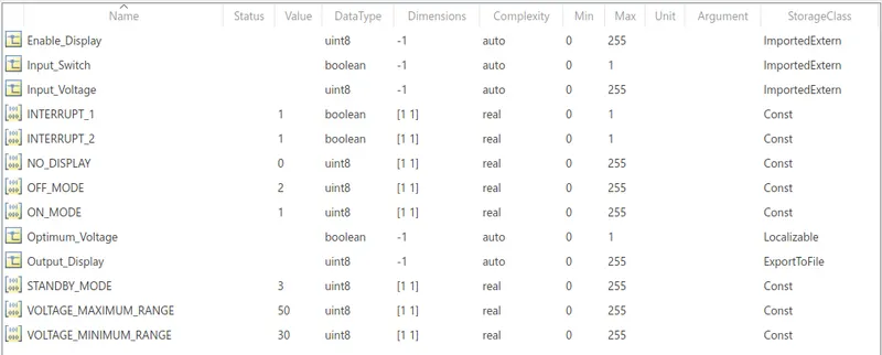
- A new Simulink data dictionary is created and updated signals & calibration Data List as per our requirements.
- The very first thing that we will do is create a Simulink Data Dictionary using the given Signal and Calibration Data List.
The following is the SLDD file :
Solver configuration parameter:
- Solver type: Fixed
- Solver: discrete (no continuous states)
- Sample time: 0.01
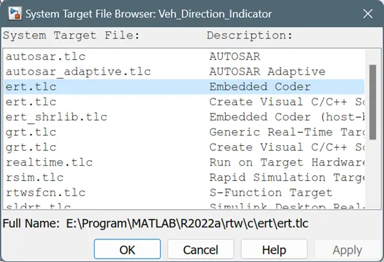
Code generation Parameters:
- System target file: ert.tlc ( Embedded Coder)
MATLAB Simulink Model Designing :-
Requirement No 1:
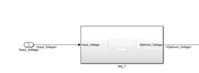
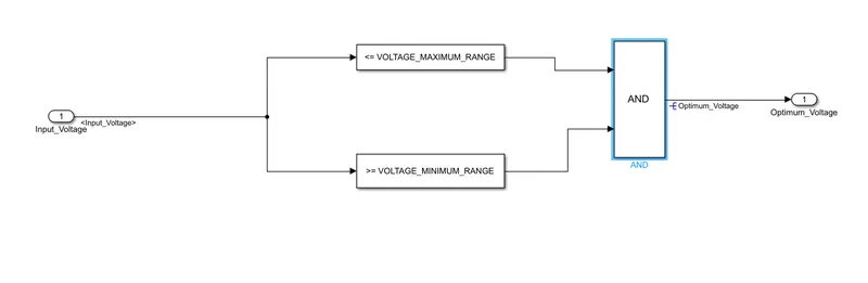
- Input Signal “Input_Voltage” is compared against voltage values “VOLTAGE_MINIMUM_RANGE” & “VOLTAGE_MAXIMUM_RANGE”.
- Incoming input signal “Input_Voltage” must be greater than – equal to “VOLTAGE_MINIMUM_RANGE” and less than – equal to “VOLTAGE_MAXIMUM_RANGE”.
- Output signal from here is “Optimum_Voltage” which will be one of the inputs to the subsystem “DisplayUnit”.
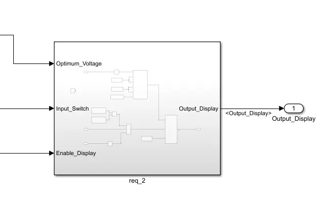
Inside the subsystem-
Requirement No 2 (DisplayUnit Subsystem):
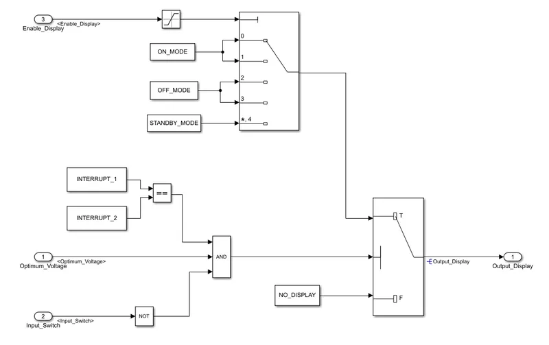
- Input Signals are “Optimum_Voltage”, “Input_Switch”, and “Enable_Display”. Signal “Enable_Display” must be saturated between the range 0 – 7. The output signal from the subsystem is “Output_Display”.
- Input Signal “Enable_Display” is compared against a pre-defined set of values in a multiport switch. The total data ports in the multiport switch are 5.
- Multiport switch inputs 1 & 2 are connected to calibration signal “ON_MODE”, Multiport switch inputs 3 & 4 are connected to calibration signal “OFF_MODE” while Multiport switch input 5 is connected to calibration signal “STANDBY_MODE”.
- The output from the Multiport switch is connected to the first input port of the Switch block. The third input port of the Switch block is connected to the calibration signal “NO_DISPLAY”.
- Meanwhile NOT the value of the input signal “Input_Switch” is compared in an AND gate against the input signal “Optimum_Voltage” and the output from comparing if calibration signals “INTERRUPT_1” & “INTERRUPT_2” are equal. The output of the AND gate is the second input of the switch block.
- The output from the switch block is “Output_Display”.
Inside the subsystem-
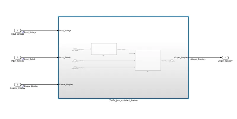
Complete Model-
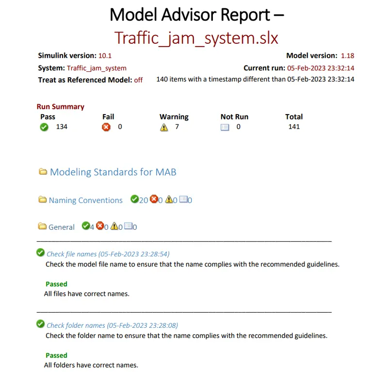
MAB Check Report-
Code Generation Report:-
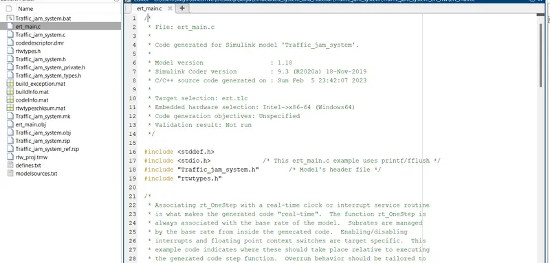
All Reports and model are attached in zip file.