Project 1- Traffic Jam Assistant Feature
Objective -
To develop one specific requirement of Traffic Jam Assistant algorithm which would predominantly feature in the IPC algorithm while following the given process
- The model should be developed in MATLAB Simulink as per MBD guidelines.
- To create Simulink Data Dictionary for the model & link it to the model.
- To generate Model Advisor Report for this project.
- To generate C Code for the developed model.
- Code Generation Profile must be in Embedded Coder.
About -
- Traffic Jam Assistant is one of the most common feature in Advanced Driver Assistance System.
- Traffic Jam Assistant helps the driver arrive more relaxed at their destination, even in dense traffic or in traffic jams.
- As a partially automated comfort function, the system takes over the longitudinal & lateral guidance of the vehicle.
- This means that the car can drive off, accelerate & brake automatically, as well as steer the vehicle within certain constraints.
- The driver has to permanently supervise the system & be ready to take over the complete control of the vehicle at any time.
- Traffic Jam Assistant system helps to avoid rear end collisions in dense traffic conditions & traffic jams.
- In Traffic jams, the vehicle takes over driving off, acceleration, braking and steering within same lane.
Basic Principle -
- Traffic Jam Assistant is based on the sensors and the functionality of the Adaptive Cruise Control (ACC) with stop & go and Lane Keeping Support (LKS).
- When ACC ‘Stop & Go’ is turned ON, the Traffic Jam Assistant continuously analyses the speed of the surrounding vehicles and compares it with the own driving speed.
- If the system detects dense traffic or a traffic jam at speeds less than 60 kmph, the driver can activate the functionality by press of a button.
- The vehicle will now automatically follow the vehicle in front, takes over driving off, acceleration, braking and steering within same lane.
- Information regarding the Traffic Jam Assistant will be available to be displayed to the driver in the Instrument Panel Cluster (IPC).
- The Algorithm which the students need to implement here in this project is predominantly based on IPC units.
Configuration Settings -
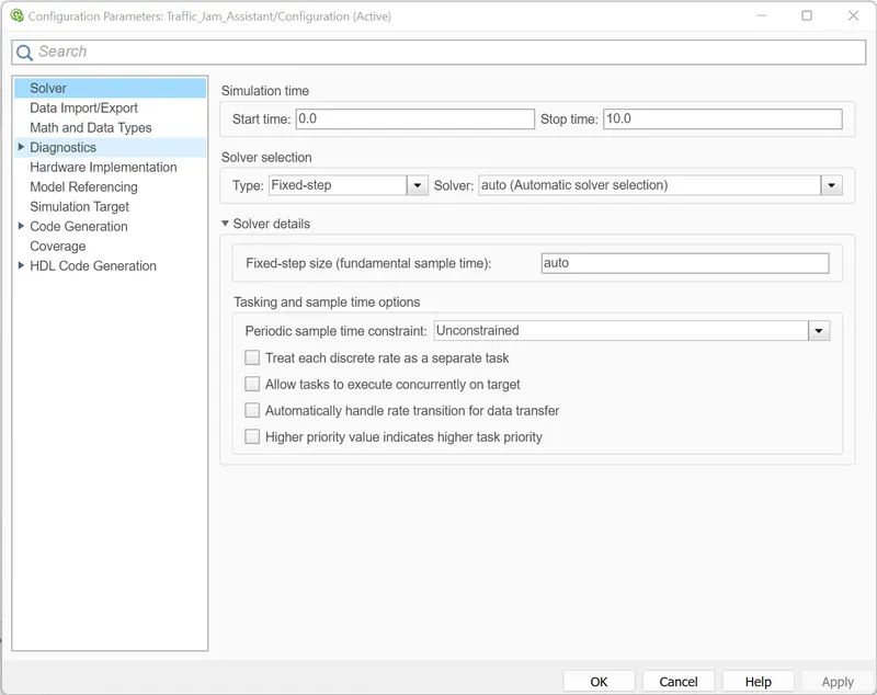
- Solver Settings -
- For Solver Settings, change the solver to Fixed Step Solver.
- Code Generation Settings -
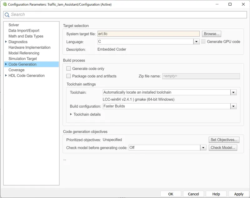
- In the Code Generation Settings, Embedded Coder has to be selected.
- Select ert.tlc for embedded coder as System Target File.
- Click Apply.
Simulink Data Dictionary File -
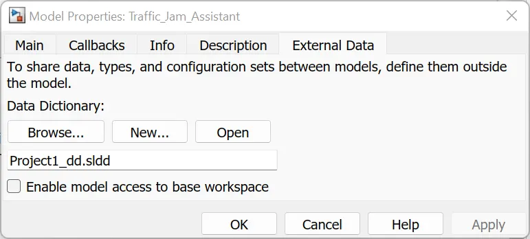
- To create a new Data Dictionary file, goto Modelling Tab.
- In the Design drop down select Link to Data Dictionary.
- Select New and provide name for the data dictionary file.
- Uncheck the box for base workspace access.
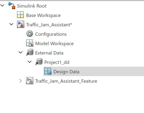
- After creating sldd file, open this file from Model Explorer.
- Expand the Model, goto External Data and select the sldd file.
- Expand it and select Design Data.
- In the Design Data, to add an entry for signals select Simulink Signals
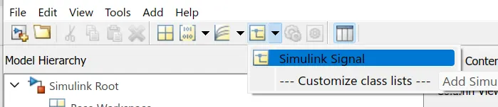
- Provide attributes to the signal as provided in the Document
- And to add an entry for variables select Simulink Parameter.
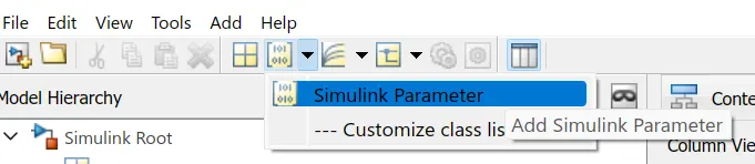
- Provide attributes to the parameter as given in the document.
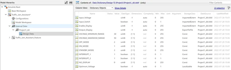
- The storage class provided are
- For Input Signals -> ImportedExtern
- For Output Signals -> ExportToFile
- For Local Signals -> Localizable
- For Constants -> Const
- After making all the entries of the given data, save the file.
- The sldd is shown below
Model Development -
- For developing the model, a subsystem is taken to implement the logic as given in Requirement Document.
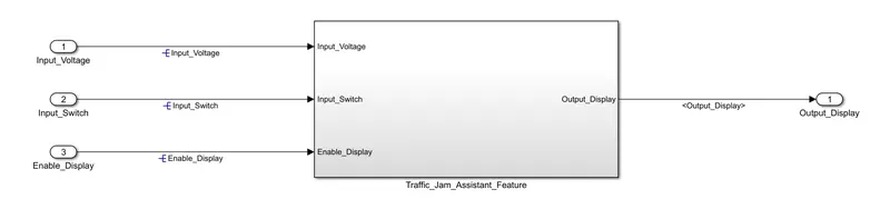
- In this subsystem, for every requirement one subsystem is created.
- As two requirements ae given so two subsystems are taken.
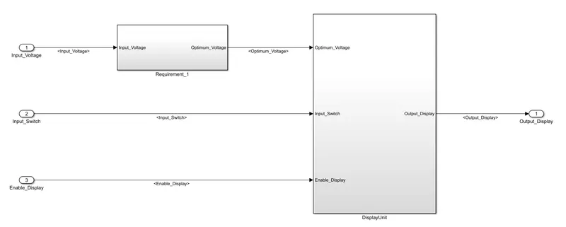
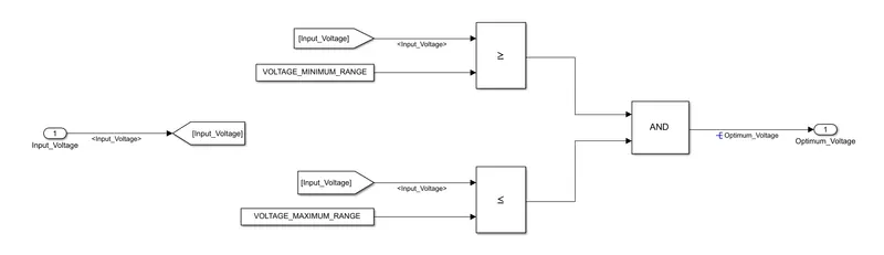
- For Requirement 1, following statements are given
- Input Signal “Input_Voltage” is compared against voltage values “VOLTAGE_MINIMUM_RANGE” & “VOLTAGE_MAXIMUM_RANGE”.
- Incoming input signal “Input_Voltage” must be greater than – equal to “VOLTAGE_MINIMUM_RANGE” and less than – equal to “VOLTAGE_MAXIMUM_RANGE”.
- Output signal from here is “Optimum_Voltage” which will be one of the inputs to the subsystem “DisplayUnit”.
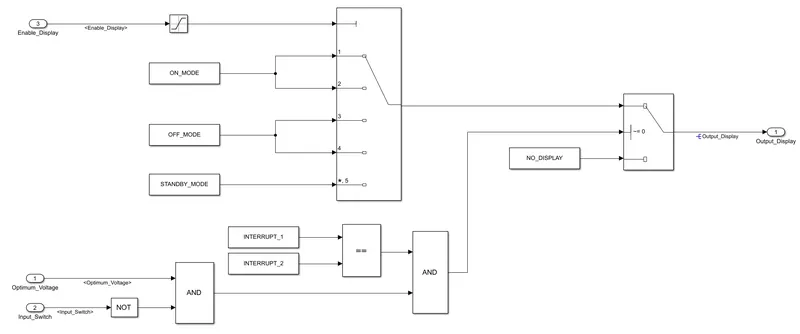
- For Requirement 2, following statements are given
- Input Signals are “Optimum_Voltage”, “Input_Switch”,“Enable_Display”.
- Signal “Enable_Display” must be saturated between the range 0 – 7.
- Output signal from the subsystem is “Output_Display”.
- Input Signal “Enable_Display” is compared against pre – defined set of values in a multiport switch.
- Total data ports in the multiport switch is 5.
- Multiport switch inputs 1 & 2 is connected to calibration signal “ON_MODE”, Multiport switch inputs 3 & 4 is connected to calibration signal “OFF_MODE” while Multiport switch input 5 is connected to calibration signal “STANDBY_MODE”.
- The output from Multiport switch is connected to the first input port of the Switch block.
- The third input port of the Switch block is connected to the calibration signal “NO_DISPLAY”.
- Meanwhile NOT value of input signal “Input_Switch” is compared in an AND gate against input signal “Optimum_Voltage” and the output from comparing if calibration signals “INTERRUPT_1” & “INTERRUPT_2” are equal.
- The output of the AND gate is the second input of the switch block.
- The output from the switch block is “Output_Display”.
Requirement Tagging and Traceability -
- To Tag the Requirement Document to the model developed, open the requirement document.
- Select the words that has to linked.
- In the model right click on the subsystem which has to be linked.
- In the Requirements option select Link to selection in Word.
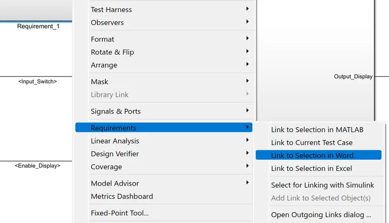
- This will link the subsystem with document.
- To check whether the link has created or not, again go to Requirements option.
- There will be a link shown with the words selected as in Document.
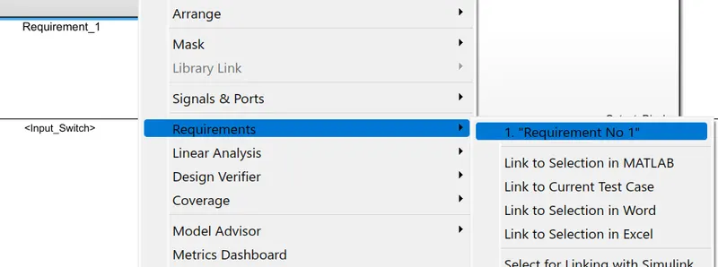
- Repeats this for all requirements.
Signal Resolving and Propagation -
- The signal has to resolved when it is first introduced in the model.
- To link signal attributes given in the sldd in the model, select the signal.
- In the Signal Properties give the name of the signal as given in the sldd.
- Check the box for Resolve the signal.
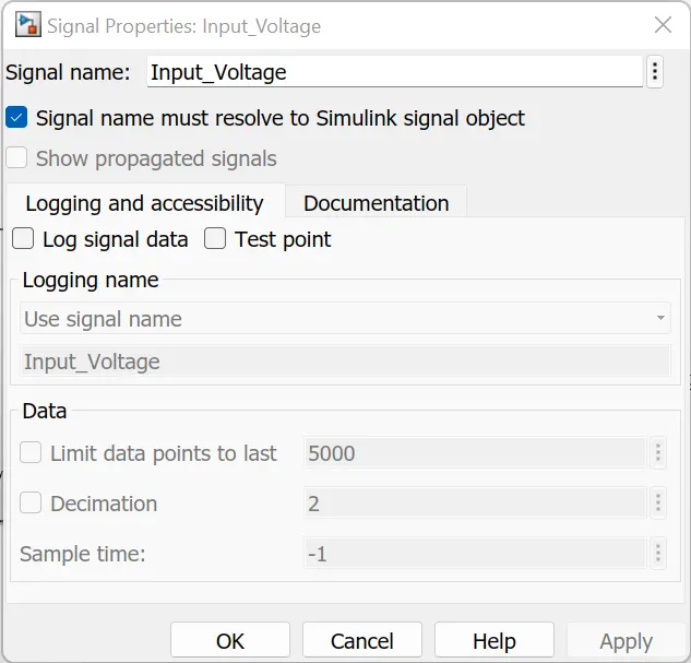
- Click OK.
- A blue symbol appears in front of signal name as shown
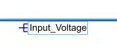
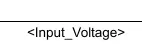
- And when the signal is continuing in subsystems so this signal has to be propagated.
- For this propagation, select the continuing signal and open the signal properties.
- Check the box for Propagated Signal.
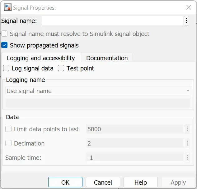
- The signal name shows between <> for propagated signals.
- Repeat the steps for resolving and propagation for all signals.
Model Advisor Report -
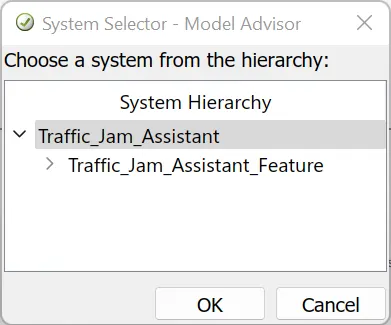
- To check the model developed is on par with MAB guildelines, open Model Advisor Tool.
- In this Tool, select the full model to check.
- Uncheck the preselected tests.
- Select only Modelling Standards for MAB test.
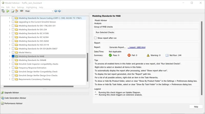
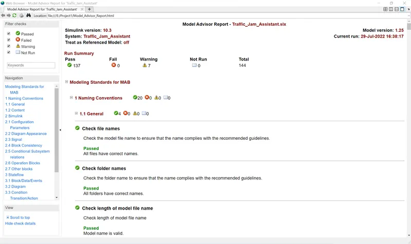
- In this test there are total of 144 tests.
- Run the selected check.
- After running the check it shows 129 tests Passed, 0 Fail and 15 Warnings.
- To rectify the warnings goto warnings and follow the given procedure given in the description.
- After rectifying all the possible warnings, again run this check.
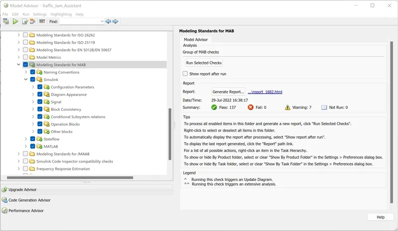
- Now the warnings reduced to 7.
- Now generate the report for this check done.
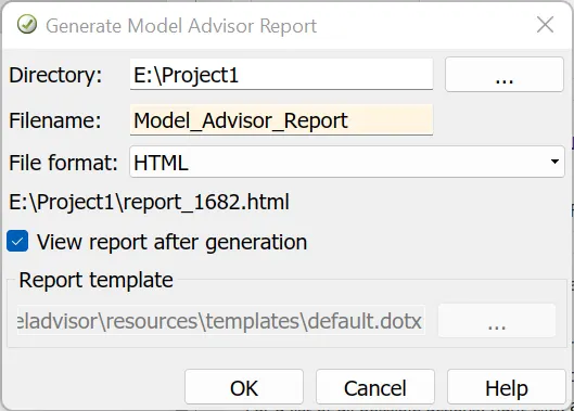
- The generated report is shown below
Code Generation -
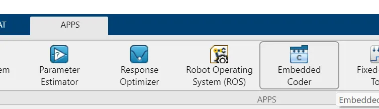
- To generate the C Code for the developed model, select the Embedded Coder in the App Menu.
- In the coder, select the Build option.
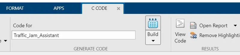
- The generated code is shown below
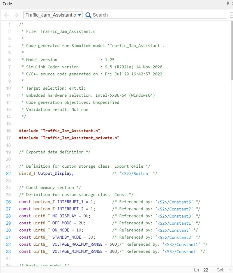
C Code -
*
2	 * File: Traffic_Jam_Assistant.c
3	 *
4	 * Code generated for Simulink model 'Traffic_Jam_Assistant'.
5	 *
6	 * Model version                  : 1.25
7	 * Simulink Coder version         : 9.5 (R2021a) 14-Nov-2020
8	 * C/C++ source code generated on : Fri Jul 29 16:42:57 2022
9	 *
10	 * Target selection: ert.tlc
11	 * Embedded hardware selection: Intel->x86-64 (Windows64)
12	 * Code generation objectives: Unspecified
13	 * Validation result: Not run
14	 */
15
16	#include "Traffic_Jam_Assistant.h"
17	#include "Traffic_Jam_Assistant_private.h"
18
19	/* Exported data definition */
20
21	/* Definition for custom storage class: ExportToFile */
22	uint8_T Output_Display;                /* '<S2>/Switch' */
23
24	/* Const memory section */
25	/* Definition for custom storage class: Const */
26	const boolean_T INTERRUPT_1 = 1;       /* Referenced by: '<S2>/Constant6' */
27	const boolean_T INTERRUPT_2 = 1;       /* Referenced by: '<S2>/Constant7' */
28	const uint8_T NO_DISPLAY = 0U;         /* Referenced by: '<S2>/Constant3' */
29	const uint8_T OFF_MODE = 2U;           /* Referenced by: '<S2>/Constant1' */
30	const uint8_T ON_MODE = 1U;            /* Referenced by: '<S2>/Constant' */
31	const uint8_T STANDBY_MODE = 3U;       /* Referenced by: '<S2>/Constant2' */
32	const uint8_T VOLTAGE_MAXIMUM_RANGE = 50U;/* Referenced by: '<S3>/Constant1' */
33	const uint8_T VOLTAGE_MINIMUM_RANGE = 30U;/* Referenced by: '<S3>/Constant' */
34
35	/* Real-time model */
36	static RT_MODEL_Traffic_Jam_Assistan_T Traffic_Jam_Assistant_M_;
37	RT_MODEL_Traffic_Jam_Assistan_T *const Traffic_Jam_Assistant_M =
38	  &Traffic_Jam_Assistant_M_;
39
40	/* Model step function */
41	void Traffic_Jam_Assistant_step(void)
42	{
43	  /* local block i/o variables */
44	  boolean_T Optimum_Voltage;
45	  uint8_T tmp;
46
47	  /* Logic: '<S3>/AND' incorporates:
48	   *  Constant: '<S3>/Constant'
49	   *  Constant: '<S3>/Constant1'
50	   *  Inport: '<Root>/Input_Voltage'
51	   *  RelationalOperator: '<S3>/Relational Operator1'
52	   *  RelationalOperator: '<S3>/Relational Operator2'
53	   */
54	  Optimum_Voltage = ((Input_Voltage >= VOLTAGE_MINIMUM_RANGE) && (Input_Voltage <=
55	    VOLTAGE_MAXIMUM_RANGE));
56
57	  /* Switch: '<S2>/Switch' incorporates:
58	   *  Constant: '<S2>/Constant6'
59	   *  Constant: '<S2>/Constant7'
60	   *  Inport: '<Root>/Input_Switch'
61	   *  Logic: '<S2>/AND'
62	   *  Logic: '<S2>/AND1'
63	   *  Logic: '<S2>/NOT'
64	   *  RelationalOperator: '<S2>/Equal'
65	   */
66	  if ((INTERRUPT_1 == INTERRUPT_2) && (Optimum_Voltage && (!Input_Switch))) {
67	    /* Saturate: '<S2>/Saturation' incorporates:
68	     *  Inport: '<Root>/Enable_Display'
69	     */
70	    if (Enable_Display < 7) {
71	      tmp = Enable_Display;
72	    } else {
73	      tmp = 7U;
74	    }
75
76	    /* End of Saturate: '<S2>/Saturation' */
77
78	    /* MultiPortSwitch: '<S2>/Multiport Switch' */
79	    switch (tmp) {
80	     case 1:
81	      /* Switch: '<S2>/Switch' incorporates:
82	       *  Constant: '<S2>/Constant'
83	       */
84	      Output_Display = ON_MODE;
85	      break;
86
87	     case 2:
88	      /* Switch: '<S2>/Switch' incorporates:
89	       *  Constant: '<S2>/Constant'
90	       */
91	      Output_Display = ON_MODE;
92	      break;
93
94	     case 3:
95	      /* Switch: '<S2>/Switch' incorporates:
96	       *  Constant: '<S2>/Constant1'
97	       */
98	      Output_Display = OFF_MODE;
99	      break;
100
101	     case 4:
102	      /* Switch: '<S2>/Switch' incorporates:
103	       *  Constant: '<S2>/Constant1'
104	       */
105	      Output_Display = OFF_MODE;
106	      break;
107
108	     default:
109	      /* Switch: '<S2>/Switch' incorporates:
110	       *  Constant: '<S2>/Constant2'
111	       */
112	      Output_Display = STANDBY_MODE;
113	      break;
114	    }
115
116	    /* End of MultiPortSwitch: '<S2>/Multiport Switch' */
117	  } else {
118	    /* Switch: '<S2>/Switch' incorporates:
119	     *  Constant: '<S2>/Constant3'
120	     */
121	    Output_Display = NO_DISPLAY;
122	  }
123
124	  /* End of Switch: '<S2>/Switch' */
125	}
126
127	/* Model initialize function */
128	void Traffic_Jam_Assistant_initialize(void)
129	{
130	  /* (no initialization code required) */
131	}
132
133	/* Model terminate function */
134	void Traffic_Jam_Assistant_terminate(void)
135	{
136	  /* (no terminate code required) */
137	}
138
139	/*
140	 * File trailer for generated code.
141	 *
142	 * [EOF]
143	 */
Goggle Drive Link - https://drive.google.com/file/d/1UD7Fim7xqVbeysiQsrWtIlgyTCXhCDm-/view?usp=sharing