Project 1- Traffic Jam Assistant Feature
SOLUTION :To develop one specific requirement of Traffic Jam Assistant algorithm which would predominantly feature in the IPC algorithm.
We are given two requirements here , according to which the model is developed .here only a small single feature of the Traffic Signal assistant is done.
Requirement No 1:
- Input Signal “Input_Voltage” is compared against voltage values “VOLTAGE_MINIMUM_RANGE” & “VOLTAGE_MAXIMUM_RANGE”.
- Incoming input signal “Input_Voltage” must be greater than – equal to “VOLTAGE_MINIMUM_RANGE” and less than – equal to “VOLTAGE_MAXIMUM_RANGE”.
- Output signal from here is “Optimum_Voltage” which will be one of the inputs to the subsystem “DisplayUnit”.
Requirement No 2 (DisplayUnit Subsystem):
- Input Signals are “Optimum_Voltage”, “Input_Switch”,“Enable_Display”. Signal “Enable_Display” must be saturated between the range 0 – 7. Output signal from the subsystem is “Output_Display”.
- Input Signal “Enable_Display” is compared against pre – defined set of values in a multiport switch. Total data ports in the multiport switch is 5.
- Multiport switch inputs 1 & 2 is connected to calibration signal “ON_MODE”, Multiport switch inputs 3 & 4 is connected to calibration signal “OFF_MODE” while Multiport switch input 5 is connected to calibration signal “STANDBY_MODE”.
- The output from Multiport switch is connected to the first input port of the Switch block. The third input port of the Switch block is connected to the calibration signal “NO_DISPLAY”.
- Meanwhile NOT value of input signal “Input_Switch” is compared in an AND gate against input signal “Optimum_Voltage” and the output from comparing if calibration signals “INTERRUPT_1” & “INTERRUPT_2” are equal. The output of the AND gate is the second input of the switch block.
- The output from the switch block is “Output_Display”.
We are supposed to create an SLDD File with all the required Signals in the system .
We are given the signals and the parameters as :
Input Signals:
|
Name of the Signal |
Data Type |
Range |
|
Input_Voltage |
uint8 |
0 - 255 |
|
Input_Switch |
boolean |
0 – 1 |
|
Enable_Display |
uint8 |
0 - 255 |
Output Signal:
|
Name of the Signal |
Data Type |
Range |
|
Output_Display |
uint8 |
0 - 255 |
Calibration Signals:
|
Name of the Signal |
Data Type |
Range |
Initial Value |
|
VOLTAGE_MINIMUM_RANGE |
uint8 |
0 – 255 |
30 |
|
VOLTAGE_MAXIMUM_RANGE |
uint8 |
0 – 255 |
50 |
|
OFF_MODE |
uint8 |
0 – 255 |
2 |
|
ON_MODE |
uint8 |
0 – 255 |
1 |
|
STANDBY_MODE |
uint8 |
0 – 255 |
3 |
|
INTERRUPT_1 |
boolean |
0 – 1 |
1 |
|
INTERRUPT_2 |
boolean |
0 - 1 |
1 |
|
NO_DISPLAY |
uint8 |
0 – 255 |
0 |
Local Signal:
|
Name of the Signal |
Data Type |
Range |
|
Optimum_Voltage |
boolean |
0 - 1 |
All these signals are properly added into an SLDD file named 'trafficjam.sldd' ,which looks like :
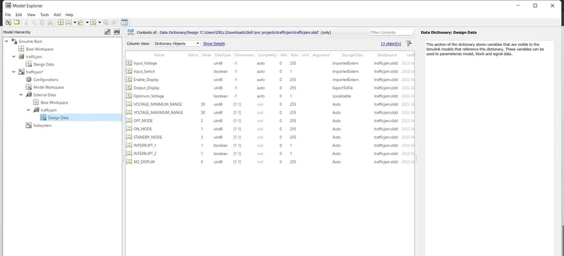
This SLDD File is linked to this Model by going into the Model Properties and from there we LINK TO THE NEW DICTIONARY Added .
Now we deveop the model according to the given requirements.
An input signal named 'Input_Voltage' is given as input to the subsystem, which is compared with 2 extreme range values of voltage. This will be fed as output voltage only if the value remains in this range of voltage .
So relational operators , a logical AND Gate and also some constant blocks for the Calliberation signals are added here .
The initial requirement will be like :
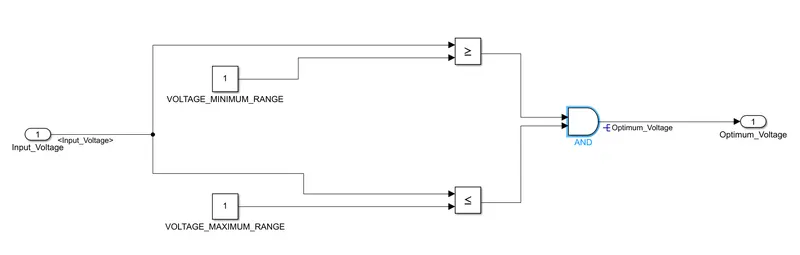
The output from this subsystem: 'Optimum_Voltage' is taken as the input for the next subsystem (treated as a local signal ) , also there are two more other inputs to that subsystem ,namely : 'Enable_Display' and 'Input_Switch'.
Enable_Display is the control signal given to the Multiport Switch block , which is fed with the help of a SATURATION Block ranging from 0 to 7 , as given in the requirement .
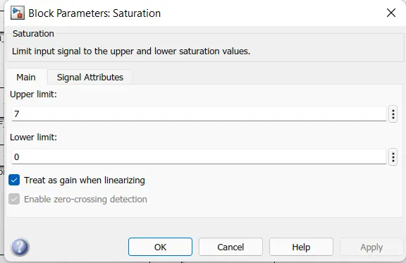
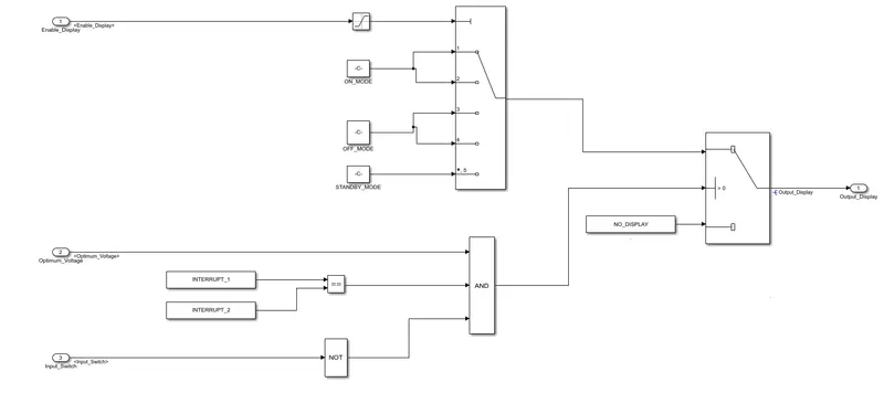
There is another switch with one input to it as the output of this Multiport Switch output and the other one as a NO_DISPLAY Block .
Control signal to this switch is obtained from a logical AND Gate , which has 1 input , the 'Input_Switch' and the other input is the 'Optimum_Voltage' which is the output of the reqyirement1 subsystem . The other input to this model is the output of a relational equal operator where the inputs to this are 2 Interrupt Signals treated as calliberation signals here .
Now we get that as :
So we have developed the main model as :
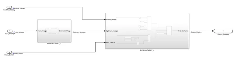
All the signals are resolved properly according to the SLDD file information and they are propagated at the respective locations correctly.
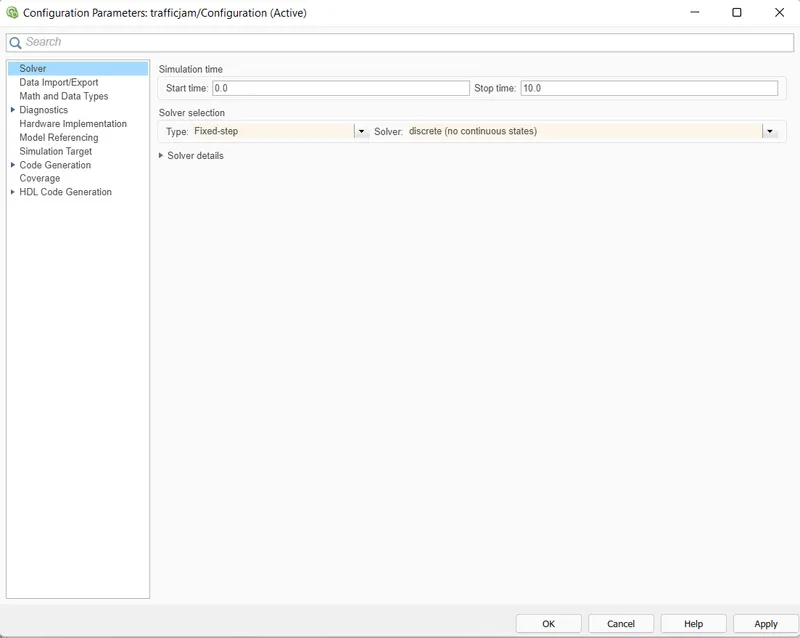
Now we goto Model Settngs and there we change the Solver from Variable to Fixed , and then into discrete .
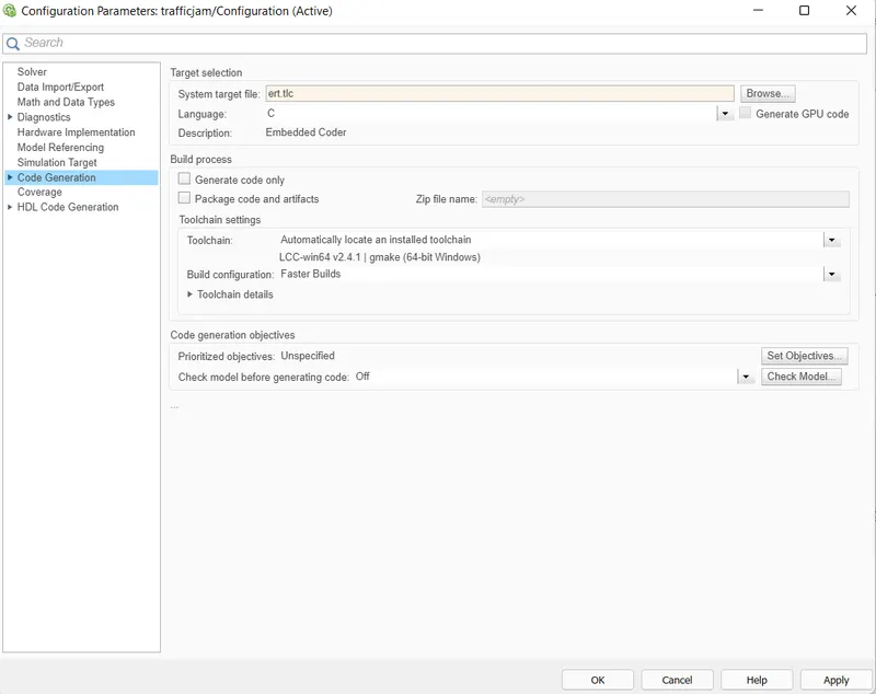
Also the Target file is set from the default 'grt.tlc' to 'ert.tlc' for the Embedded Coder .
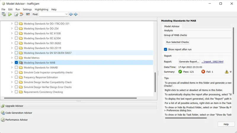
After doing this we does the Model advisory check, this is done by going to the Modelling tab and then selecting Model Advisor, from where we does the MAB Guidelines check for our model .
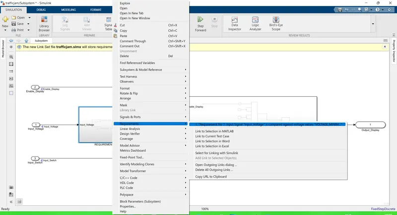
Proper requirement tagging is also done for the model by right clicking on the susbsytem and the Requirement settings , we link it to the Word file created with the objective of the project mainly tagging the requirement1 .
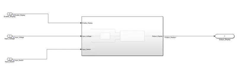
So finally after all the model will look as shown in the figure below ;
Now after this , we are supposed to generate code for this model . For that we go to the APPS TAB, There the option for Embedded Coder is selected , and then the Code will be generated once we click the BUILD Button on the toolbar .
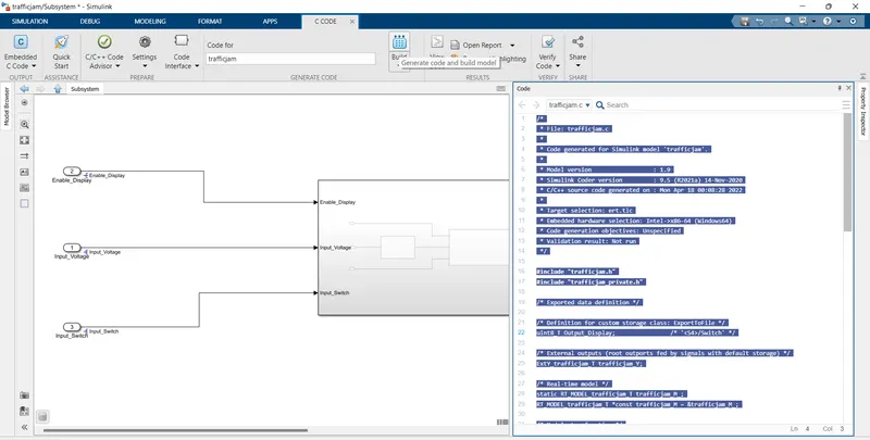
Now an EMBEDDED CODE is generated according to the Model and the Code is attached to the program as follows :
/*
 * File: trafficjam.c
 *
 * Code generated for Simulink model 'trafficjam'.
 *
 * Model version                  : 1.9
 * Simulink Coder version         : 9.5 (R2021a) 14-Nov-2020
 * C/C++ source code generated on : Mon Apr 18 00:08:28 2022
 *
 * Target selection: ert.tlc
 * Embedded hardware selection: Intel->x86-64 (Windows64)
 * Code generation objectives: Unspecified
 * Validation result: Not run
 */

#include "trafficjam.h"
#include "trafficjam_private.h"

/* Exported data definition */

/* Definition for custom storage class: ExportToFile */
uint8_T Output_Display;                /* '<S4>/Switch' */

/* External outputs (root outports fed by signals with default storage) */
ExtY_trafficjam_T trafficjam_Y;

/* Real-time model */
static RT_MODEL_trafficjam_T trafficjam_M_;
RT_MODEL_trafficjam_T *const trafficjam_M = &trafficjam_M_;

/* Model step function */
void trafficjam_step(void)
{
  /* local block i/o variables */
  boolean_T Optimum_Voltage;

  /* Logic: '<S3>/AND' incorporates:
   *  Constant: '<S3>/VOLTAGE_MAXIMUM_RANGE'
   *  Constant: '<S3>/VOLTAGE_MINIMUM_RANGE'
   *  Inport: '<Root>/Input_Voltage'
   *  RelationalOperator: '<S3>/GreaterThanOrEqual'
   *  RelationalOperator: '<S3>/LessThanOrEqual'
   */
  Optimum_Voltage = ((Input_Voltage >= 30) && (Input_Voltage <= 50));

  /* Switch: '<S4>/Switch' incorporates:
   *  Logic: '<S4>/Logical Operator'
   */
  if (Optimum_Voltage && trafficjam_ConstB.RelationalOperator &&
      trafficjam_ConstB.LogicalOperator1) {
    /* Switch: '<S4>/Switch' */
    Output_Display = trafficjam_ConstB.MultiportSwitch;
  } else {
    /* Switch: '<S4>/Switch' incorporates:
     *  Constant: '<S4>/.'
     */
    Output_Display = 0U;
  }

  /* End of Switch: '<S4>/Switch' */
}

/* Model initialize function */
void trafficjam_initialize(void)
{
  /* (no initialization code required) */
}

/* Model terminate function */
void trafficjam_terminate(void)
{
  /* (no terminate code required) */
}

/*
 * File trailer for generated code.
 *
 * [EOF]
 */
CONCLUSION :
* The Model is developed according to the MAB Guidelines .
* SLDD File is created for the given signals and it is linked to the model .
* Model advisory check is done and the report generated is attached here .
* CODE is generated for the model .