Project 1 - Review of Shear & Moment Connections in RAM Connection
Question-
Design and optimize typical shear, moment and Splice joints in RAM Connection for the following structure modelled in Staad Pro. Design and optimize base plate connection.
Structure: A 2D portal frame fixed support spanning 15m with a pitched roof ridge height of 12m, slope of 4 degrees. A uniformly distributed load of 10kN/m is applied on the roof beams. Optimize the beams and columns for 85% utilization and consider splice joints at 6m from base and 4m from beam column joints. Consider a hanger beam shear connected with column support of 4m height from the splice joint with a length of 3m from beam-column corner joint carrying 5kN/m load. Use hot rolled sections.
Ans=
AIM:- To Design and optimize typical shear, moment and Splice joints in RAM Connection for a 2D portal frame fixed support spanning 15m with a pitched roof ridge height of 12m, slope of 4 degrees.
INTRODUCTION:-
I will create a 2D portal frame in Staad.pro software for a fixed support spanning 15m with a pitched roof ridge height of 12m, slope of 4 degrees. A uniformly distributed load of 10kN/m is applied on the roof beams. Then I will create the aforementioned joint in Ram Connection along with given load, then Optimize the beams and columns for 85% utilization and consider splice joints at 6m from base and 4m from beam column joints. Consider a hanger beam shear connected with column support of 4m height from the splice joint with a length of 3m from beam-column corner joint carrying 5kN/m load. Use hot rolled sections.
PROCEDURE:-
Step-1
Given Data -
i) Supports 2D Frame : Fixed support
ii) Span : 15m
iii) Roof : Pitched roof
iv) Ridge height : 12m
v) Slope : 4 degrees
vi) Load : UDL of 10 kN/m on roof beam
vii) Stees Section : Hot rolled
viii) Splice joint location : At 6 m from base
ix) Hanger beam : Shear connected with column support of 4 m height from splice joint with a length of 3m with a beam
column corner joint carrying 5 kN/m load.
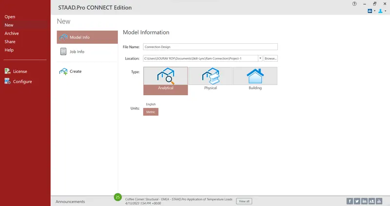
i) Initially Open the Staad software
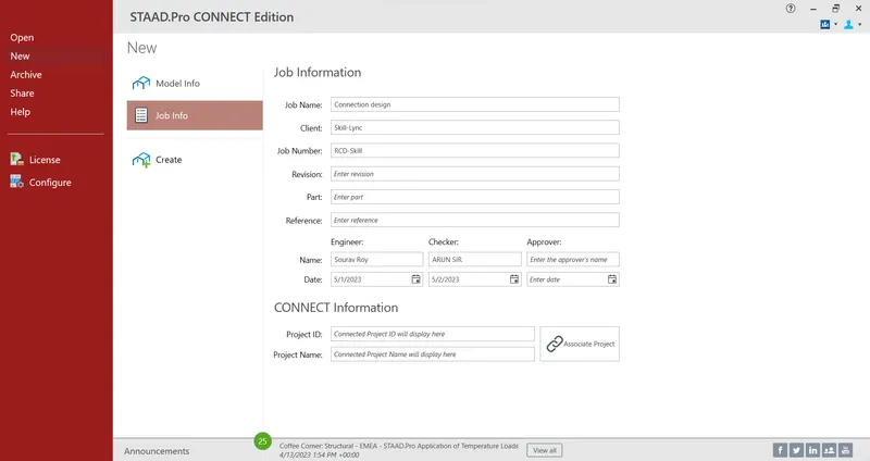
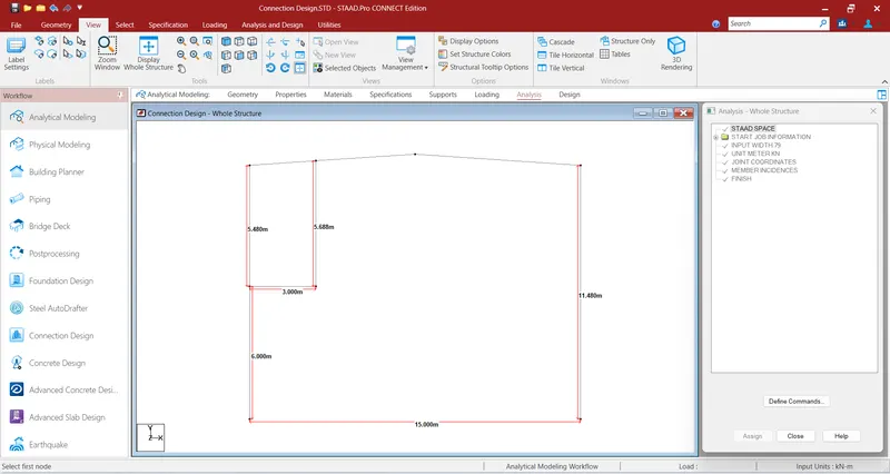
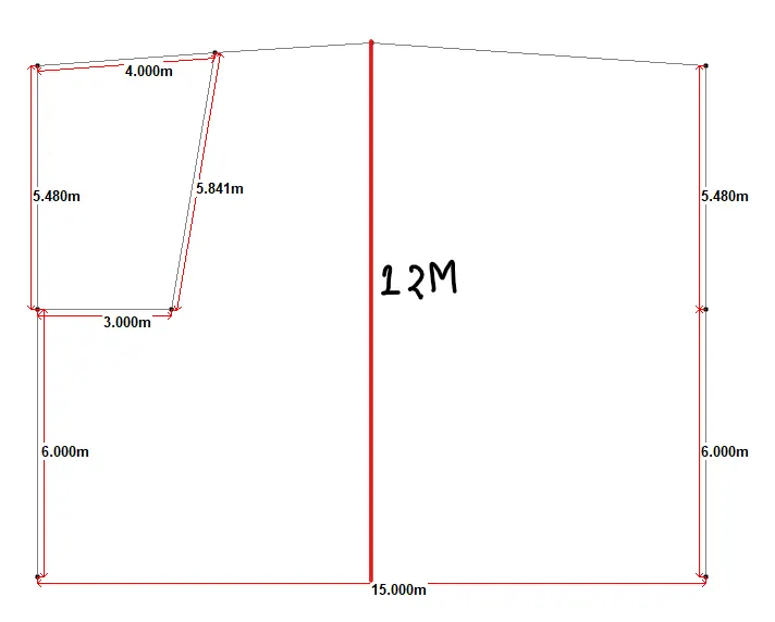
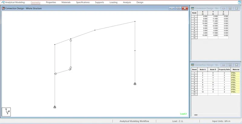
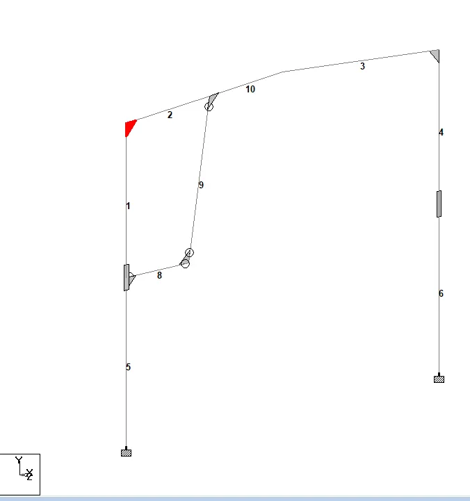
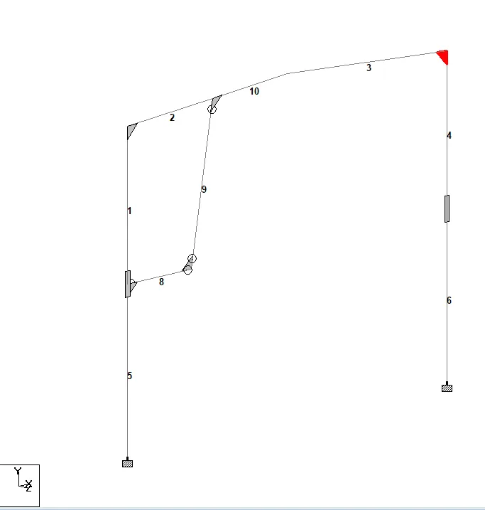
ii) And create a geometry of 2D frame.
iii) Total Ht = 12 m from base to ridge
So Ht of Column = Tan (4) = X / 7.5
Therefor X = 0.52m
Therefore Ht of Column = Total Ht - Ridge Ht
= 12 - 0.52
= 11.48 m
Now release moments at joints
Step-2
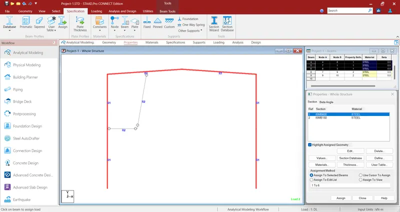
Properties
i) An ISMB 600 is assigned for Columns
ii) An ISMB 600 is assigned for Rafter Beams-
iii) An ISMB 150 is assigned for Hanger beams
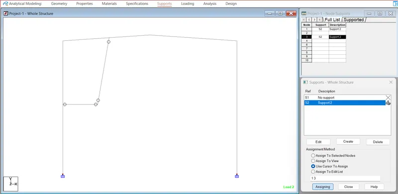
Add fixed support
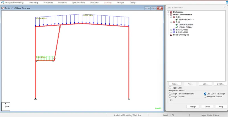
Step 3) Loading -
i) Self-weight in the form of Dead load is assigned
ii) Live load of 10 Kn/m as UDL on roof beam is assigned
iii) Live load of 5 Kn/m as UDL on hanger beam is assigned
3D view of 2D frame -
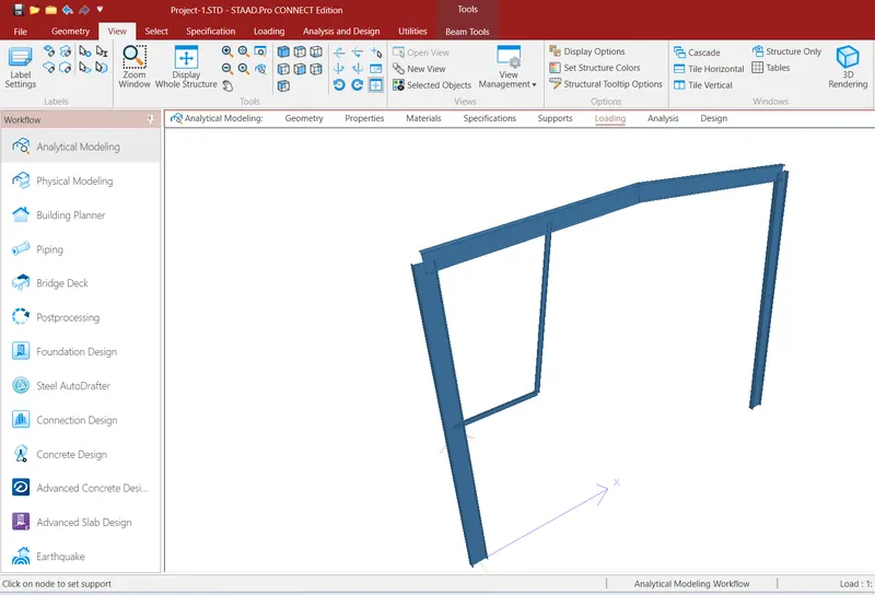
Step 4) Analysis
i) Run the Model to check the members utilization ratio .
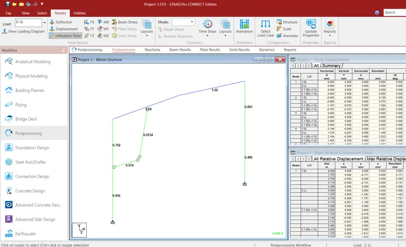
Now Go to Connection Design tab:-
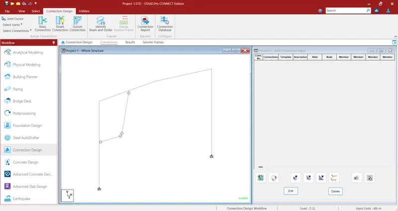
Now create joint for connection
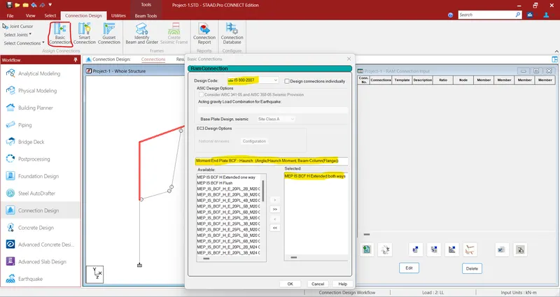
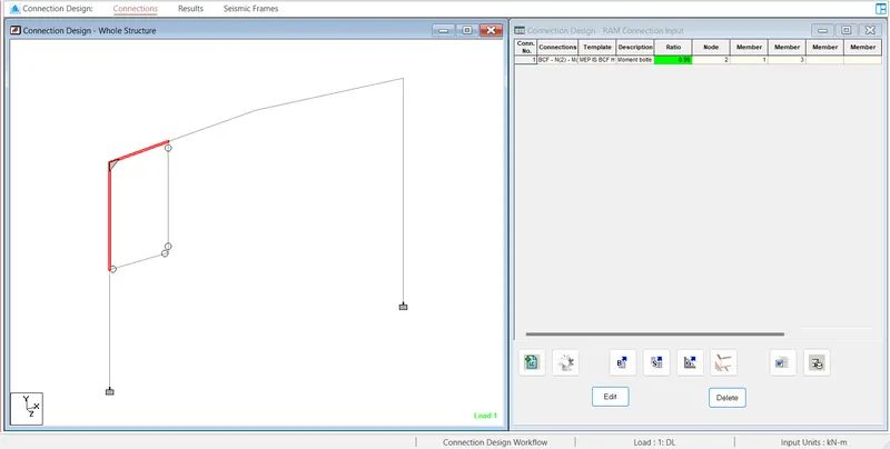
Apply the template of Moment end plate of BCF Haunch
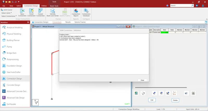
After applying the template
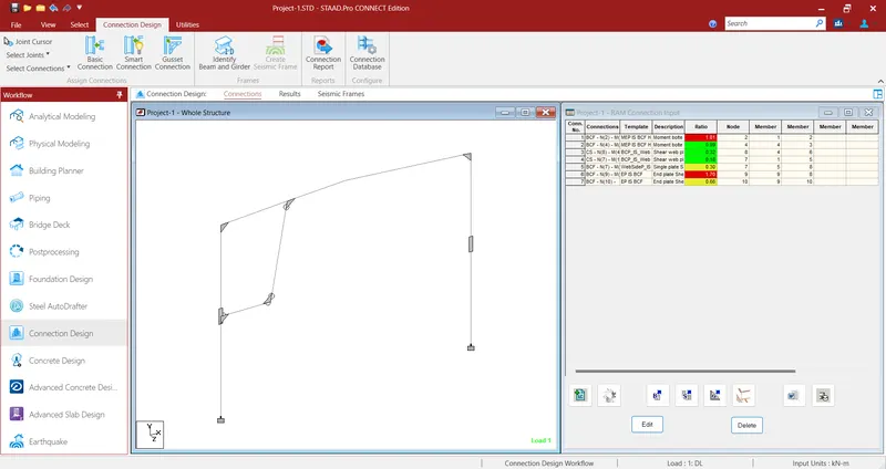
By the use of smart connection option I will create all other joints
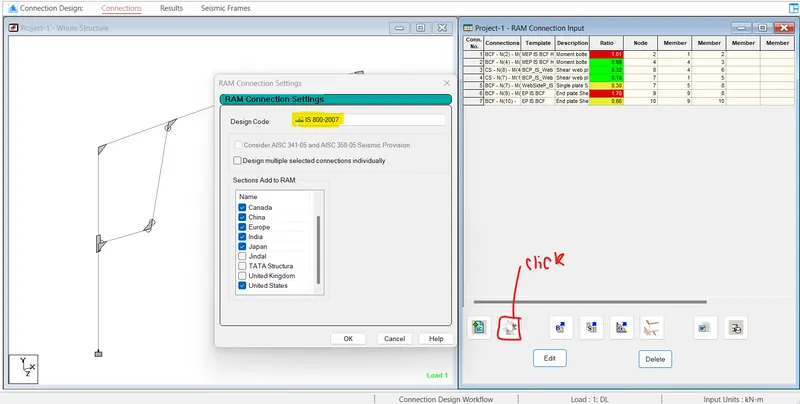
Now select the Ram Connection design code and tick additional template options from different origins
Now optimize each joints 85% and to do this select joint cursor, then double click on joints via this cursor
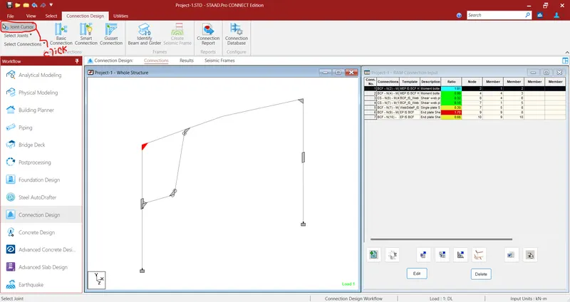
Step 5) Shear, moment and splice joints are created as shown below
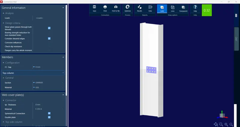
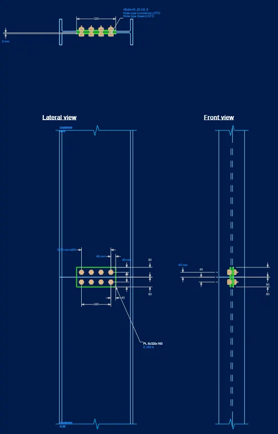
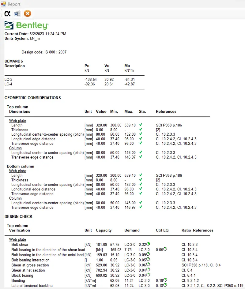
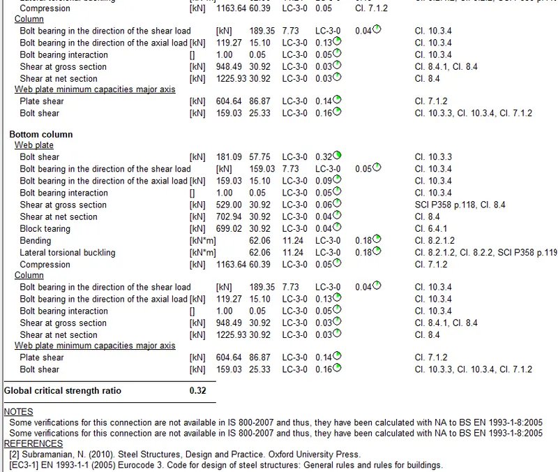
1) Bolted splice connection between Columns web is created beween member M (4 , 6)
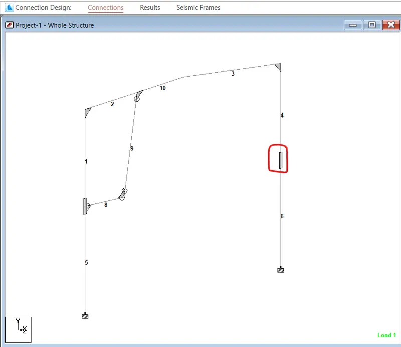
ii) Further Optimization is done to reduce the utilization ratio (32% optimization utilization)
iii) DXF view
iv) Steel Report
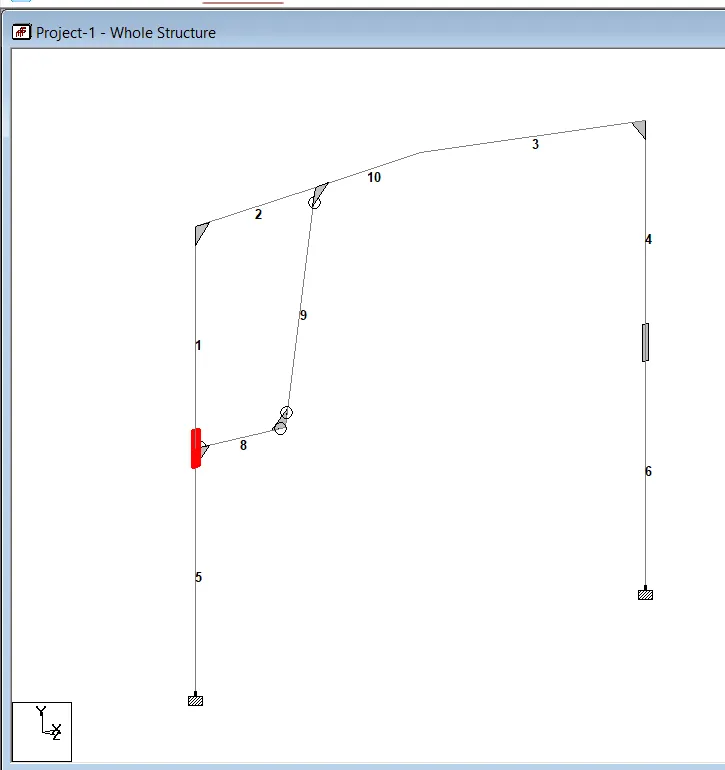
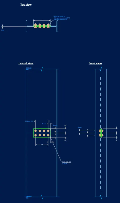
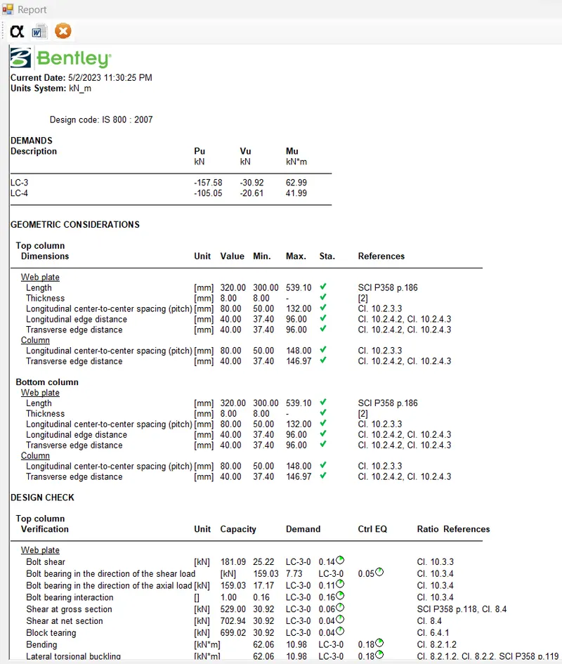
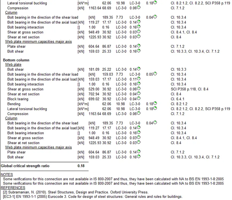
2) Bolted splice connection between Columns web is created beween member M (1 , 5)
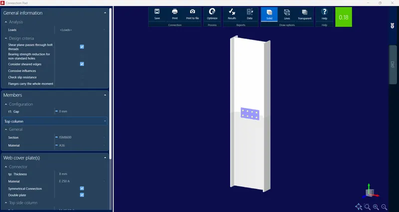
ii) Further Optimization is done to reduce the utilization ratio (18% optimized utilization)
iii) DXF view
iv) Steel Report
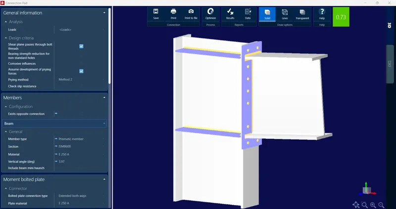
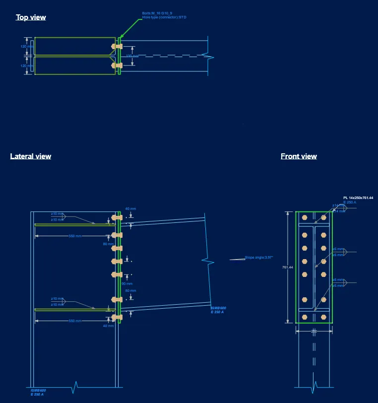
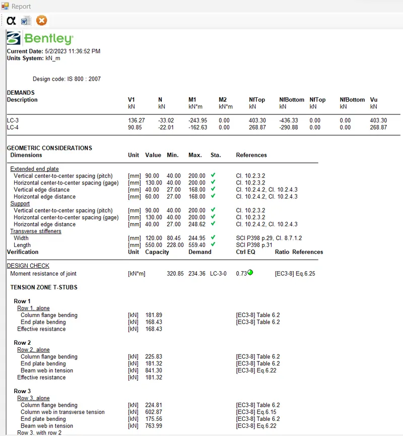
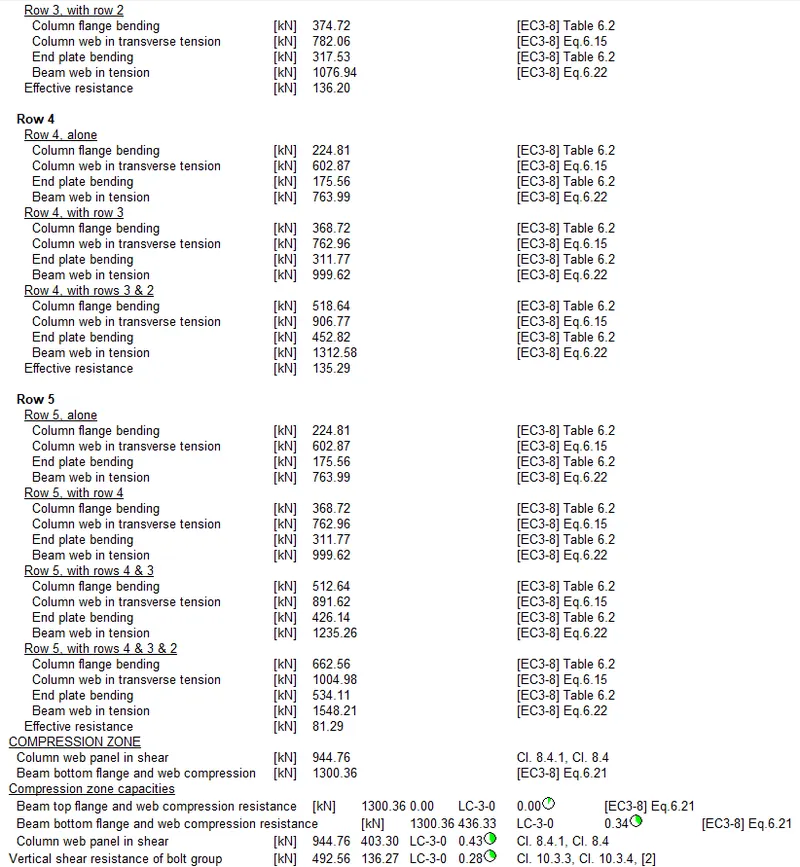
3) Beam column flange bolted moment joint is between member M (1,2)
Note - Two addition extended flange plates are provided to Column Flange to transfer the moment.(73% optimized utilization)
ii) DXF view
iii) Steel Report -
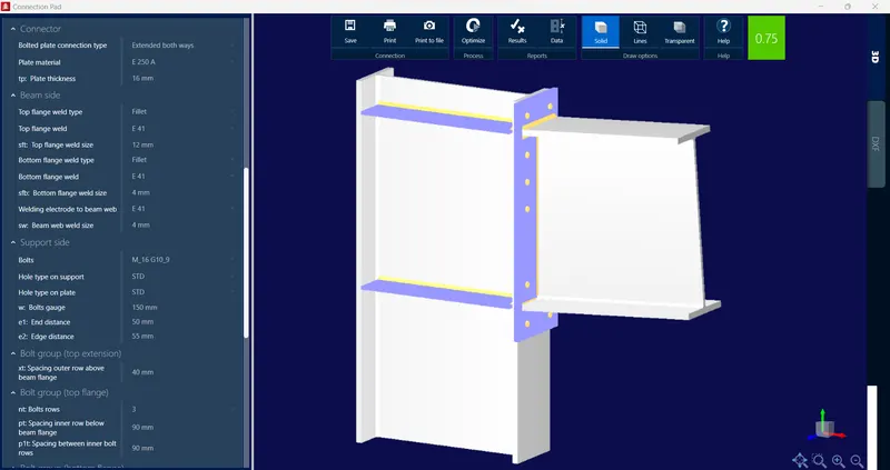
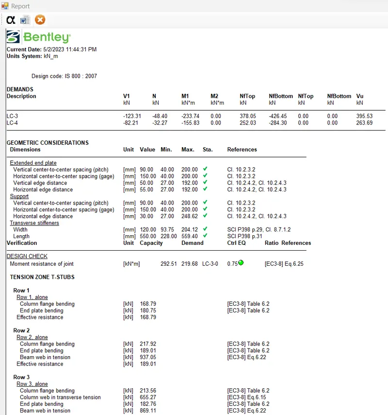
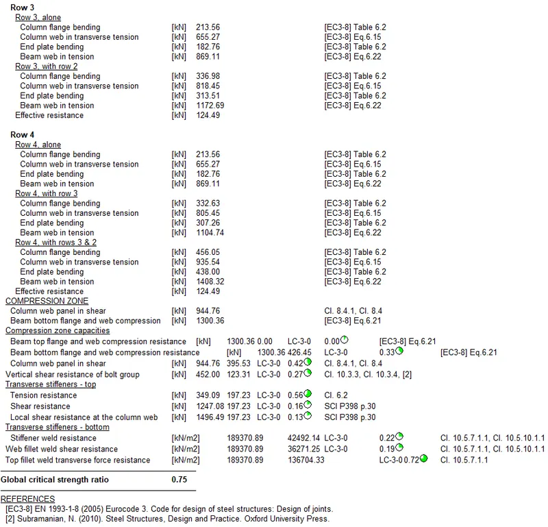
4) Beam column flange bolted moment joint is between member M (3,4)
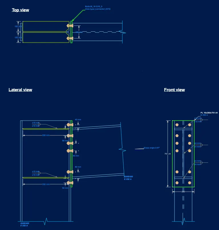
Note - Two additional extended stiffner plates are provided to Column Flange to transfer the moment. (75% optimized utilization)
ii) DXF view
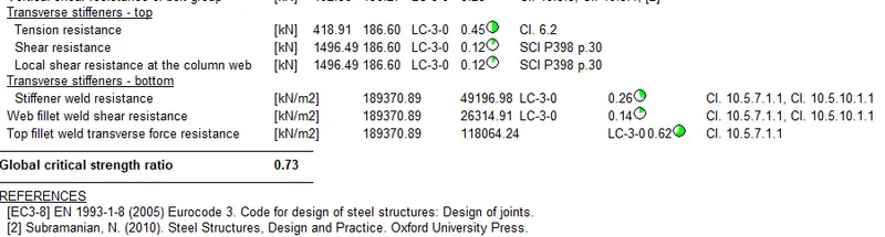
iii) Steel Report -
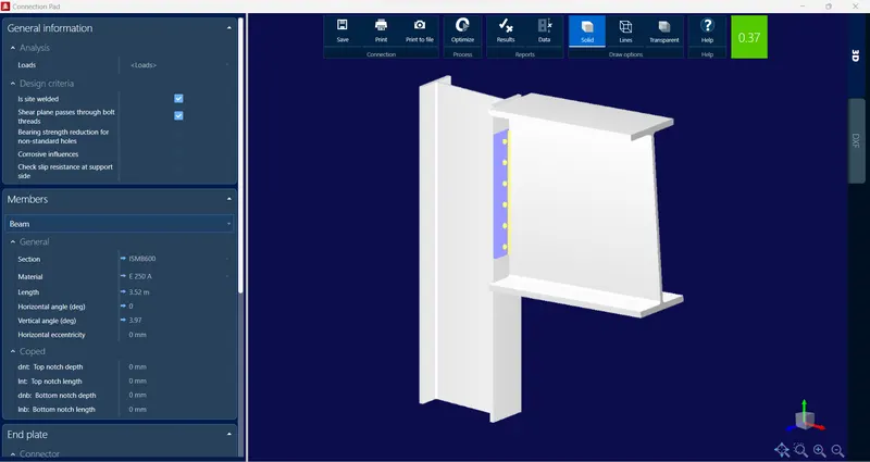
5) Beam column flange bolted moment joint is between member M (2, 9, 10)
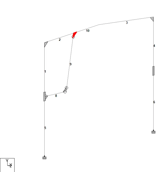
Note - Thick Connection plate is provided to Column Flange to transfer the moment. (37% optimized utilization)
ii) DXF view
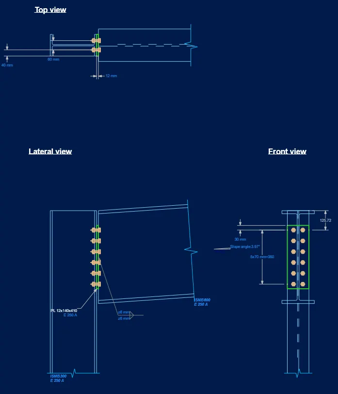
iii) Steel Report -
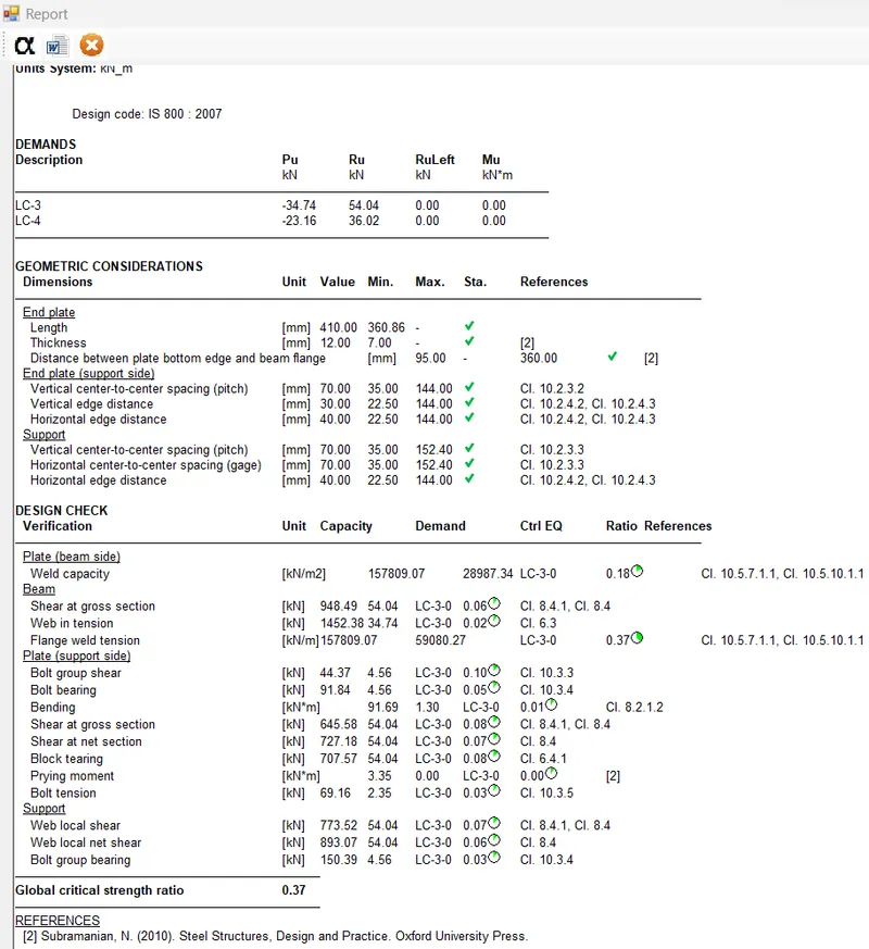
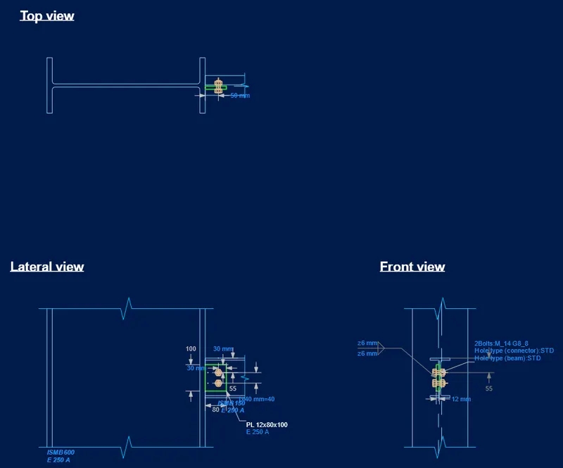
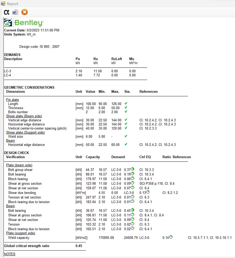
6) Beam column flange End Plate shear connection between member M( 5 , 8)
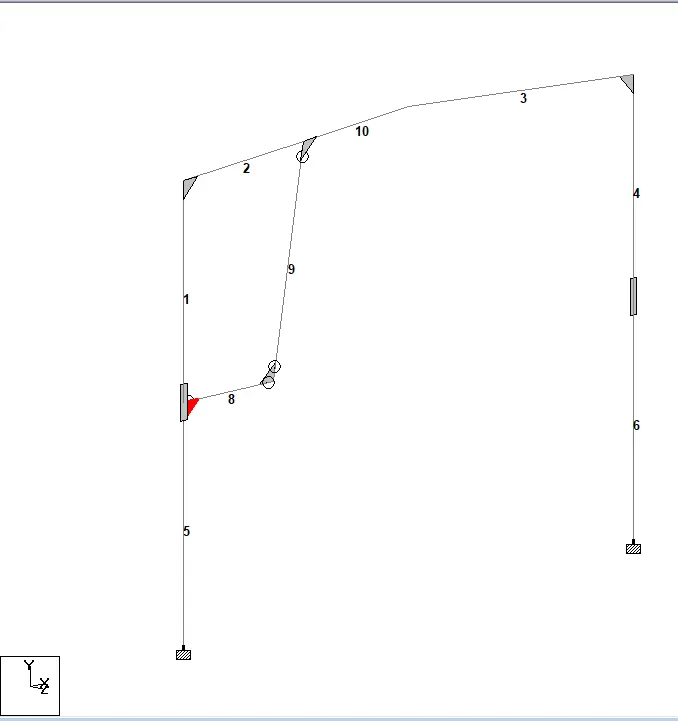
Connection optimized with 45% utilization
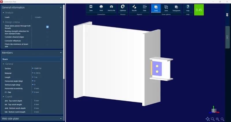
DXF View -
iii) Steel Report -
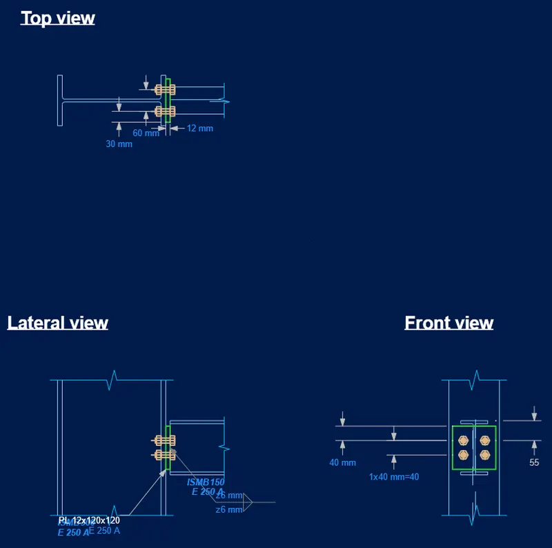
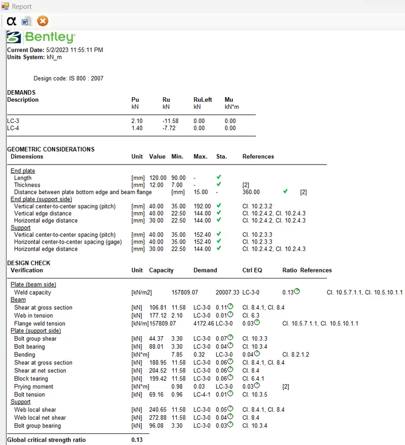
7) Beam column flange End Plate shear connection between member M( 9 , 8)
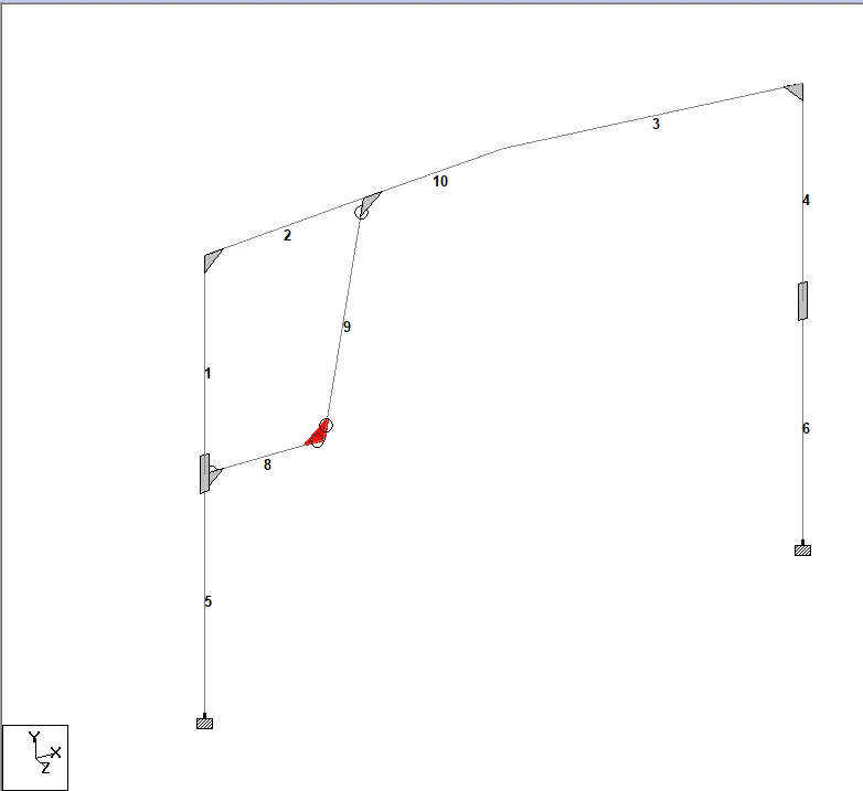
Connection optimized with 13% utilization
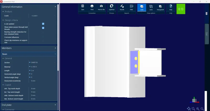
DXF View -
iii) Steel Report -
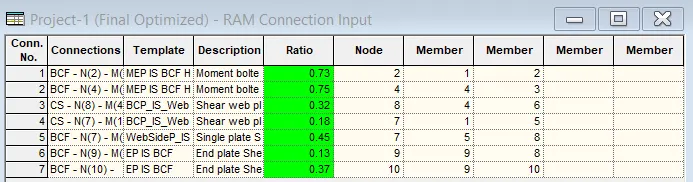
RESULT:-
i) The 2D Portal frame is created in staad.pro with given data and typical shear, moment and slice joint in
RAM connection for 2D portal frame are designed and optimized below 85%
Apart from that, I have attached Staad.pro file along with word file output of each joint design calculation details for further reference.