Project-1: Powertrain for aircraft in runways
PROJECT :1
Powertrain for aircraft in runways
PART A
Objective:1 Search and list out the total weight of various types of aircrafts.
An average airplane weighs around 90,000 pounds (41,000 kilos) empty weight, which means the weight of the airplane when its fuel tanks are empty and there are no people or luggage on board. This example is for a B-737-800 aircraft .The aircraft gross weight (also known as the all-up weight and abbreviated AUW) is the total aircraft weight at any moment during the flight or ground operation.
An aircraft's gross weight will decrease during a flight due to fuel and oil consumption. An aircraft's gross weight may also vary during a flight due to payload dropping or in-flight refueling.
At the moment of releasing its brakes, the gross weight of an aircraft is equal to its takeoff weight. During flight, an aircraft's gross weight is referred to as the en-route weight or in-flight weight.
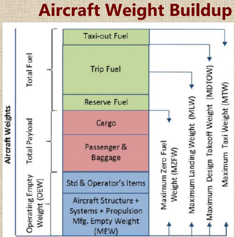
Maximum design taxi weight (MDTW)
The maximum design taxi weight (also known as the maximum design ramp weight (MDRW)) is the maximum weight certificated for aircraft maneuvering on the ground (taxiing or towing) as limited by aircraft strength and airworthiness requirements.
Maximum design takeoff weight (MDTOW)
Is the maximum certificated design weight when the brakes are released for takeoff and is the greatest weight for which compliance with the relevant structural and engineering requirements has been demonstrated by the manufacturer.
Maximum design landing weight (MDLW)
The maximum certificated design weight at which the aircraft meets the appropriate landing certification requirements. It generally depends on the landing gear strength or the landing impact loads on certain parts of the wing structure.The MDLW must not exceed the MDTOW.
Maximum design zero-fuel weight (MZFW)
The maximum certificated design weight of the aircraft less all usable fuel and other specified usable agents (engine injection fluid, and other consumable propulsion agents).
All up Weight(AUP): It can be written as DOW+ Payload Fuel
| Type | MTOW [kg] | MLW [tonnes] | TOR [m] | LR [m] | ICAO category | FAA category |
|---|---|---|---|---|---|---|
| Antonov An-225 | 640,000 | 591.7 | 3500 | Heavy | Super | |
| Scaled Composites Model 351 Stratolaunch | 589,670 | 3660 | Heavy | Super | ||
| Airbus A380-800[1][2][3] | 575,000 | 394 | 3100 | 1930 | Super | Super |
| Boeing 747-8F | 447,700 | 346.091 | 3100 | 1800 | Heavy | Heavy |
| Boeing 747-8 | 443,613 | 306.175 | 3100 | Heavy | Heavy | |
| Boeing 747-400ER | 412,770 | 295.742 | 3090 | Heavy | Heavy | |
| Antonov An-124-100M | 405,060 | 330 | 2520 | 900 | Heavy | Heavy |
| Boeing 747-400 | 396,900 | 295.742 | 3018 | 2179 | Heavy | Heavy |
| Lockheed C-5 Galaxy[4][5][6] | 381,000 | 288.417 | 2530 | 1494 | Heavy | Heavy |
| Boeing 747-200[7] | 377,840 | 285.700 | 3338 | 2109 | Heavy | Heavy |
| Boeing 747-300[7] | 377,840 | 260.320 | 3222 | 1905 | Heavy | Heavy |
| Airbus A340-500[8] | 371,950 | 240 | 3050 | 2010 | Heavy | Heavy |
| Airbus A340-600[8] | 367,400 | 256 | 3100 | 2100 | Heavy | Heavy |
| Boeing 777F | 347,800 | 260.816 | 2830 | Heavy | Heavy | |
| Boeing 777-300ER | 351,800 | 251.29 | 3100 | Heavy | Heavy | |
| Boeing 777-200LR | 347,450 | 223.168 | 3000 | Heavy | Heavy | |
| Boeing 747-100[7] | 340,200 | 265.300 | Heavy | Heavy | ||
| Airbus A350-1000 | 308,000 | 233.5 | Heavy | Heavy | ||
| Boeing 777-300 | 299,370 | 237.683 | 3380 | Heavy | Heavy | |
| Boeing 777-200ER | 297,550 | 213.00 | 3380 | 1550 | Heavy | Heavy |
| Airbus A340-300[8][9] | 276,700 | 190 | 3000 | 1926 | Heavy | Heavy |
| McDonnell Douglas MD-11 | 273,300 | 185 | 2990 | 1890 | Heavy | Heavy |
| Airbus A350-900 | 270,000 | 175 | 2670 | 1860 | Heavy | Heavy |
| Ilyushin Il-96M | 270,000 | 195.04 | 3115 | 2118 | Heavy | Heavy |
| McDonnell Douglas DC-10 | 256,280 | 183 | 2990 | 1890 | Heavy | Heavy |
| Boeing 787-9[10] | 254,000 | 192.777 | 2900 | Heavy | Heavy | |
| Boeing 787-10[10] | 254,000 | 201.849 | Heavy | Heavy | ||
| Airbus A340-200[8][11] | 253,500 | 181 | 2990 | Heavy | Heavy | |
| Airbus A330-900 | 251,000 | 191,000 | 3100 | Heavy | Heavy | |
| Ilyushin IL-96-300 | 250,000 | 175 | 2600 | 1980 | Heavy | Heavy |
| Airbus A330-300[12][13] | 242,000 | 185 | 2500 | 1750 | Heavy | Heavy |
| Airbus A330-200[12][13] | 242,000 | 180 | 2220 | 1750 | Heavy | Heavy |
| Lockheed L-1011-500 | 231,300 | 166.92 | 2636 | Heavy | Heavy | |
| Boeing 787-8[10] | 228,000 | 172.365 | 3300 | 1695 | Heavy | Heavy |
| Lockheed L-1011-200 | 211,400 | Heavy | Heavy | |||
| Ilyushin IL-86 | 208,000 | 175 | Heavy | Heavy | ||
| Boeing 767-400ER | 204,000 | 158.758 | 3414 | Heavy | Heavy | |
| Airbus A300-600R[14] | 192,000 | 140 | 2385 | 1555 | Heavy | Heavy |
| Boeing 767-300ER | 187,000 | 136.08 | 2713 | 1676 | Heavy | Heavy |
| Concorde | 185,000 | 111.1 | 3440 | 2220 | Heavy | Heavy |
| Airbus A300-600[14] | 163,000 | 138 | 2324 | 1536 | Heavy | Heavy |
| Boeing 767-300 | 159,000 | 136.078 | 2713 | 1676 | Heavy | Heavy |
| Airbus A310-300[14] | 157,000 | 124 | 2290 | 1490 | Heavy | Heavy |
| Vickers VC10 | 152,000 | 151.9 | Heavy | Heavy | ||
| Boeing 707-320B[15] | 151,000 | 97.5 | Heavy | Heavy | ||
| Boeing 707-320C[15] | 151,000 | 112.1 | Heavy | Heavy | ||
| Douglas DC-8-61 | 147,000 | Heavy | Heavy | |||
| Airbus A310-200[14] | 142,000 | 123 | 1860 | 1480 | Heavy | Heavy |
| Airbus A400M | 141,000 | 122 | 980 | 770 | Heavy | Heavy |
| Douglas DC-8-32 | 140,000 | Heavy | Heavy | |||
| Douglas DC-8-51 | 125,000 | Medium | Large | |||
| Boeing 757-300 | 124,000 | 101.6 | 2550 | 1750 | Medium | Large |
| Boeing 707-120B[15] | 117,000 | 86.3 | Medium | Large | ||
| Boeing 757-200 | 116,000 | 89.9 | 2347 | 1555 | Medium | Large |
| Boeing 720B[16] | 106,000 | 79.5 | Medium | Large | ||
| Boeing 720[16] | 104,000 | 79.5 | Medium | Large | ||
| Tupolev Tu-154M | 104,000 | 80 | Medium | Large | ||
| Tupolev Tu-204SM | 104,000 | 87.5 | 2250 | Medium | Large | |
| Convair 880 | 87,500 | Medium | Large | |||
| Boeing 737-900 | 85,000 | 66.36 | 2500 | 1704 | Medium | Large |
| Boeing 737-900ER | 85,000 | 71.35 | 2804 | 1829 | Medium | Large |
| Boeing 727-200 Advanced[17] | 84,000 | 70.1 | Medium | Large | ||
| Airbus A321-100[18] | 83,000 | 77.8 | 2200 | 1540 | Medium | Large |
| Boeing 737-800 | 79,000 | 65.32 | 2308 | 1634 | Medium | Large |
| Boeing 727-200[17] | 78,000 | 68.1 | Medium | Large | ||
| McDonnell-Douglas MD-83 | 73,000 | 63.28 | Medium | Large | ||
| Boeing 727-100[17] | 72,500 | 62.4 | Medium | Large | ||
| Boeing 727-100C[17] | 72,500 | 62.4 | Medium | Large | ||
| McDonnell-Douglas MD-90-30 | 71,000 | 64.41 | 2165 | 1520 | Medium | Large |
| de Havilland Comet 4 | 70,700 | Medium | Large | |||
| Boeing 737-700 | 70,000 | 58.06 | 1921 | 1415 | Medium | Large |
| Airbus A320-100[18] | 68,000 | 66 | 1955 | 1490 | Medium | Large |
| Boeing 737-400 | 68,000 | 54.9 | 2540 | 1540 | Medium | Large |
| de Havilland Comet 3 | 68,000 | Medium | Large | |||
| Boeing 377 | 67,000 | Medium | Large | |||
| Boeing 737-600 | 66,000 | 54.66 | 1796 | 1340 | Medium | Large |
| Airbus A220-300 | 65,000 | 57.61 | 1890 | 1494 | Medium | Large |
| Hawker Siddeley Trident 2E | 65,000 | Medium | Large | |||
| Airbus A319[18] | 64,000 | 62.5 | 1850 | 1470 | Medium | Large |
| Boeing 737-300 | 63,000 | 51.7 | 1939 | 1396 | Medium | Large |
| Boeing 737-500 | 60,000 | 49.9 | 1832 | 1360 | Medium | Large |
| Airbus A220-100 | 59,000 | 50.80 | 1463 | 1356 | Medium | Large |
| Airbus A318[18] | 59,000 | 57.5 | 1375 | 1340 | Medium | Large |
| Boeing 717-200HGW | 55,000 | 47.174 | 1950 | Medium | Large | |
| Douglas DC-7 | 55,000 | Medium | Large | |||
| de Havilland Comet 2 | 54,000 | Medium | Large | |||
| Boeing 717-200BGW | 50,000 | 46.265 | 1950 | Medium | Large | |
| de Havilland Comet 1 | 50,000 | Medium | Large | |||
| Douglas DC-6A | 48,600 | Medium | Large | |||
| Douglas DC-6B | 48,500 | Medium | Large | |||
| Embraer 190[19] | 48,000 | 43 | 2056 | 1323 | Medium | Large |
| Caravelle III | 46,000 | Medium | Large | |||
| Fokker 100 | 46,000 | 39.95 | 1621 | 1350 | Medium | Large |
| Douglas DC-6 | 44,000 | Medium | Large | |||
| Avro RJ-85 | 42,000 | 36.74 | Medium | Large | ||
| Handley Page Hermes | 39,000 | Medium | Large | |||
| Embraer 175[20] | 37,500 | 32.8 | 2244 | 1304 | Medium | Large |
| Bombardier CRJ900[21] | 36,500 | 33.345 | 1778 | 1596 | Medium | Large |
| Embraer 170[22] | 36,000 | 32.8 | 1644 | 1274 | Medium | Large |
| Bombardier CRJ700 | 33,000 | 30.39 | 1564 | 1478 | Medium | Large |
| Douglas DC-4 | 33,000 | Medium | Large | |||
| Vickers Viscount 800 | 30,400 | Medium | Large | |||
| Bombardier Q400 | 28,000 | 28.01 | 1219 | 1295 | Medium | Large |
| Bombardier CRJ200 | 23,000 | 21.319 | 1918 | 1479 | Medium | Large |
| ATR 72-600 | 22,800 | 22.35 | 1333 | 914 | Medium | Large |
| Saab 2000 | 22,800 | 21.5 | 1300 | Medium | Large | |
| Embraer ERJ 145 | 22,000 | 19.3 | 2270 | 1380 | Medium | Large |
| ATR 42-500 | 18,600 | 18.3 | 1165 | 1126 | Medium | Small |
| Saab 340 | 13,150 | 12.930 | 1300 | 1030 | Medium | Small |
| Embraer 120 Brasilia | 11,500 | 11.25 | 1560 | 1380 | Medium | Small |
| BAe Jetstream 41 | 10,890 | 10.570 | 1493 | 826 | Medium | Small |
| Learjet 75[23] | 9,752 | 8.709 | 1353 | 811 | Medium | Small |
| Pilatus PC-24[24] | 8,300 | 7.665 | 893 | 724 | Medium | Small |
| Embraer Phenom 300[25] | 8,150 | 7.65 | 956 | 677 | Medium | Small |
| Beechcraft 1900D | 7,765 | 7.605 | 1036 | 853 | Medium | Small |
| Cessna Citation CJ4[26] | 7,761 | 7.103 | 1039 | 896 | Medium | Small |
| de Havilland Hercules | 7,000 | Medium | Small | |||
| Embraer Phenom 100 | 4,800 | 4.43 | 975 | 741 | Light | Small |
Objective: 2 Is there any difference between ground speed and air speed.
Ground speed
It is the horizontal speed of an aircraft relative to the Earth’s surface. It is vital for accurate navigation that the pilot has an estimate of the ground speed that will be achieved during each leg of a flight.
An aircraft diving vertically would have a ground speed of zero. Information displayed to passengers through the entertainment system of airline aircraft usually gives the aircraft ground speed rather than airspeed.
Ground speed can be determined by the vector sum of the aircraft's true airspeed and the current wind speed and direction; a headwind subtracts from the ground speed, while a tailwind adds to it. Winds at other angles to the heading will have components of either headwind or tailwind as well as a crosswind component.
Air speed
It is the speed of an aircraft relative to the air through which it is moving.Airspeed is simply the speed at which an aircraft is moving relative to the air it is flying in. As such, it’s also the speed at which the air is flowing around the aircraft’s wings whereas Ground speed, on the other hand, is the aircraft’s speed relative to the ground.
In simple words, we can imagine Ground speed is how fast an airplane's shadow would move across the land. If there's a strong wind pushing an aircraft, that's reflected in the ground speed.
Airspeed, in contrast, is how fast an airplane is really flying strictly under its own power, which is calculated by subtracting the wind speed from the ground speed.
Airspeed is the vector difference between the ground speed and the wind speed. On a perfectly still day, the airspeed is equal to the ground speed. But if the wind is blowing in the same direction that the aircraft is moving, the airspeed will be less than the ground speed.
Air Speed= Ground Speed - Wind Speed
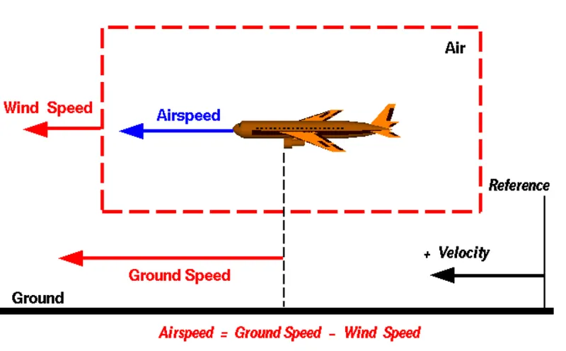
Difference between Ground Speed and Air Speed:Ground speed is the airplane’s speed relative to the surface of the Earth. Airspeed – is its speed relative to the air it is flying in.Airspeed is what determines whether there is enough airflow around an aircraft to make it fly, Ground speed is what determines how fast an aircraft will get to its destination.If there is no wind at all, then both the aircraft’s airspeed and ground speed would be the same 500 miles per hour, and the aircraft would reach its destination in four hours.Ground speed is easily and accurately determined by the GPS. Air speed is more complicated as it cannot be calculated by sensor sata. What we get is indicated airspeed
Objective3: Why is it not recommended to use aircraft engine power to move it on the ground at Airport.
Although many aircrafts are capable of moving in backward using reverse thrust, as result the jet blast or prop wash might cause damage to the terminal building or equipment. Engines close to ground may also blow sand and debris forward and then suck them into the engine, causing damage to the engine.
The risk may arise from the engine ground running relate to the potential for loss of control of the aircraft by those persons occupying the pilot seats in the flight deck.Unwanted consequences from such static running are mainly related to those arising from the movement of the aircraft engine running-effectively loss of control especially during high power engine running.
The noise generated from aircraft is also very dangerous for the passengers and people living around them.The jet blast from the engines can damage the terminal building and nearby Foreign equipment. It can even throw away people standing nearby because of huge pressure.
Engines can blow sand and debris. Engines can suck in sand and debris which can cause serious damage to the engine. It is easier for the truck driver to see the surroundings better than the pilot sitting in the cockpit with limited windows.Modern planes are huge. It is difficult to navigate such gigantic structures through limited space. An A380 is eight stories high. The pilots won't be able to see anything directly in front of them or anything behind the wings.
Hence it is not recommended to use engine power to move on ground.
Taxiing;
The vehicles used for this towing or moving from terminal to runway are called Taxiing. Here the fuel cost is also reduced to a great extent. And nowadays electric taxiing is becoming more economical and efficient way.
Electric taxiing systems use electric motors fitted inside the wheels of the aircraft’s landing gear. Electric power is supplied to these motors by an on-board Auxiliary Power Unit (APU).
Objective: 4 How is an aircraft pushed to the runway when it's ready to take off.
Airplanes have engines, and they can use them to move forward along the ground. So they push themselves to the runway.
It is true that most of the time, a small vehicle is needed to push the larger commercial airplanes backwards away from the terminal building, because even if a plane can reverse it’s thrust, it’s not always safe to hit the buildings with that reverse thrust. So the little trucks push the bigger planes back away from the buildings, but after that, the planes can apply a small amount of engine power to roll forward just as all airplanes can.
In aviation, pushback is an airport procedure during which an aircraft is pushed backward away from an airport gate by an external power. Pushbacks are carried out by special, low-profile vehicles called pushback tractors or tugs.A pushback is, therefore, the preferred method to move the aircraft away from the gate.
Since the pilots cannot see what is behind the aircraft, steering is done by the pushback tractor driver and not by the pilots. Depending on the aircraft type and airline procedure, a bypass pin may be temporarily installed into the nose gear to disconnect it from the aircraft's normal steering mechanism.
Procedure:
The pilot parks the aircraft in exactly the right place. Usually with the help of an automatic system, but occasionally guided by a marshaller waving two paddles or wands. Dozens of handling personnel are already standing by to perform a whole range of tasks simultaneously.
As soon as the aircraft is stationary and the engines are switched off, the first priority is to disembark the passengers as quickly as possible. The apron handler places chocks in front of the wheels and connects the ground power. Meanwhile, the passenger bridge maneuvers up to the door and a belt loader rolls up to the cargo hold. Luggage is unloaded and transferred to the terminal on baggage carts.
Refueling begins, usually from a hydrant at the stand. A hose is attached to this from a special vehicle called a dispenser, with the other side connected to the fuel tank in the wing. Read more about refueling here.
Meanwhile, specialists from the airline conduct a technical check to make sure that the engines, wings, control surfaces, landing gear, instruments, doors and other equipment are in full working order.
The aircraft is now ready for baggage to be loaded for the next flight. This is a quick process, on average taking only 10-15 minutes. A little later the passengers start boarding. As soon as they are all in their seats, the door is closed and the pilot informs air-traffic control that the flight is ready for departure.The apron handler removes the chocks. A so-called pushback truck reverses the aircraft into taxiing position, pushing it with a tow bar attached to the nose-wheel strut. Or, in the most modern versions, by actually lifting the wheel. That speeds up coupling and decoupling.The aircraft taxis to the runway to depart at the agreed time.
Objective: 5 Learn about take off power, tyre design, rolling resistance, tyre pressure, brake forces when Landing.
Takeoff Power:
A power take-off (PTO) is any of several methods for taking power from a power source, such as a running engin, and transmitting it to an application such as an attached implement or separate machine.
Most commonly, it is a splined drive shifted installed on a tractor or truck allowing implements with mating fittings to be powered directly by the engine.for light aircraft, usually full power is used during takeoff. Large transport category (airliner) aircraft may use a reduced power for takeoff, where less than full power is applied in order to prolong engine life, reduce maintenance costs and reduce noise emissions. In some emergency cases, the power used can then be increased to increase the aircraft's performance. Before takeoff, the engines, particularly piston engines, are routinely run up at high power to check for engine-related problems
The nose is raised to a nominal 5°–15° nose up pitch attitude to increase lift from the wings and effect liftoff. For most aircraft, attempting a takeoff without a pitch-up would require cruise speeds while still on the runway.
Fixed-wing aircraft designed for high-speed operation (such as commercial jet aircraft) have difficulty generating enough lift at the low speeds encountered during takeoff. These are therefore fitted with high-lift devices, often including slats and usually flaps, which increase the camber and often area of the wing, making it more effective at low speed, thus creating more lift. These are deployed from the wing before takeoff, and retracted during the climb. They can also be deployed at other times, such as before landing.
Tyre Design:
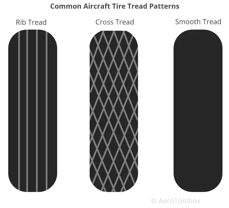
An aircraft tyre is designed to withstand extremely heavy loads while landing, take off, taxing and parking. The number of wheels required for aircraft increases with the weight of the aircraft, as the weight of the aeroplane needs to be distributed more evenly. Engineers are challenged with designing tires with cool running, heat-resistant materials while simultaneously exceeding tire service requirements.Aircraft tire tread patterns are designed to facilitate stability in high crosswind conditions, to channel water away to prevent hydroplaning, and for braking effect.
A tyre is made from rubberized fabric piles over a rubber liner and the edges of the piles are wrapped around a wire bead, which holdsthe tyre to the wheel rim. The fabric piles are covered with a rubber compound tread and a different rubber compound for the side walls. The tyre is cured in a mould to vulcanize the parts into a single unit and form the tread design.
Aircraft tires also include fusible plugs (which are assembled on the inside of the wheels), designed to melt at a certain temperature. Tires often overheat if maximum braking is applied during an aborted takeoff or an emergency landing.
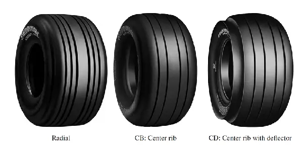
Two types of tyre are used in aircraft application, and those are bias-ply tyre and radial tyre.
Radial type ;
A typical radial tyre With their rigid belt, they provide increased landings and reduced rolling resistance. They have fewer components in their construction and are lighter than similarly sized bias ply tires. Components that differ from bias-ply construction as follows:
Overlay: A layer of reinforcing rubber coated fabric placed on top of the belts to aid in high speed operation.
Belt Plies: A composite structure that stiffens the tread area for increased landings. The belt plies increase the tire strength in the tread area.
Casing Plies: As in bias-ply tires, the casing plies are layers of rubber-coated fabric. However, unlike those in bias plies that run at opposite angles to one another, radial plies run radially from bead to bead.
Chippers: The chippers are layers of rubber-coated fabric applied at diagonal angles that improve the durability of the tire in the bead area.
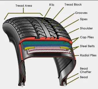
Bias-ply tyre ;
Bias-ply tires are popular choices for aircraft tires because of their durability and retreadability. The tire construction consists of the following components: The cross section of bias tyre is shown below:
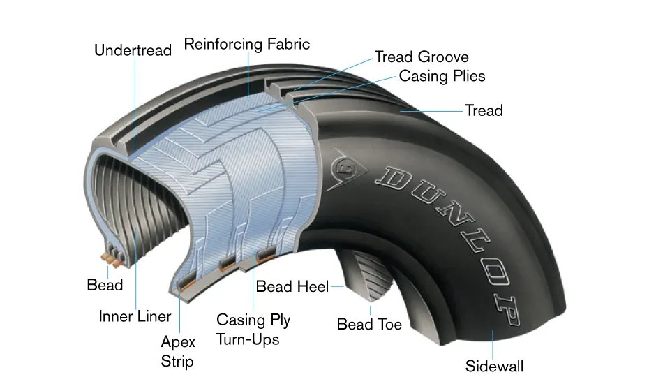
Tread: The tread is made of rubber mixed with other additives to obtain the desired level of toughness, durability, and resistance to wear.
Sidewall: The sidewall is a protective layer of rubber that covers the outer casing ply. It extends from the tread edge to the bead area.
Buff Line Cushion: The buff line cushion is made of rubber compound to enhance the adhesion between the tread reinforcing ply and the breakers or casing plies.
Breakers: Breakers are reinforcing plies of rubber-coated fabric placed under the buff line cushion to protect casing plies and strengthen and stabilize the tread area.
Casing Plies: Alternate layers of rubber-coated fabric (running at opposite angles to one another) provide the strength of the tire.
Wire Beads: Hoops of high tensile strength steel wire that anchor the casing plies and provide a firm mounting surface on the wheel. The outer edge of the bead that fits against the wheel flange is called the bead heel. The inner bead edge is called the bead toe.
Apex Strip: A wedge of rubber affixed to the top of the bead bundle.
Flippers: Layers of rubberized fabric that help anchor the bead wires to the casing and improve the durability of the tire.
Ply Turnups: The casing plies are anchored by wrapping them around the wire beads, thus forming the ply turnups.
Chafer: A protective layer of rubber and/or fabric located between the casing plies and wheel to minimize chafing.
Liner: In tubeless tires, the liner is a layer of low permeability rubber that acts as a built-in tube and restricts gas from diffusing into the casing plies. In tube-type tires, a thinner liner is used to prevent tube chafing against the inside ply.
Rolling resistance:
Rolling resistance sometimes called rolling friction/ drag, is the force resisting the motion when a body rolls on a surface. Its mainly caused by non-elastic effects that are, not all the energy needed for deformation (or movement) of the wheel, roadbed, etc., is recovered when the pressure is removed.
It is the combination of forces that work against the forward motion of your vehicle. The weight of the vehicle, gravity and inertia, the amount of friction between the tires and the road surface, and air drag all play a part. When you coast in your car or on a bike, rolling resistance is what slows you down. The more rolling resistance, the more power it takes to propel a vehicle. Between 3 and 11 percent of the gas used in passenger vehicles goes to overcoming this force, so reducing it means saving on gas.
In aircraft the friction between aircraft and runway will be proportional to the normal force exerted by the aircraft on the runway. so rolling resistance force is given by
F = crr*(W-L)
The normal force will be the difference between Weight of aircraft and Lift, the friction coefficient or the coefficient of rolling resistance(crr) will be typically of a magnitude of 0.02 for a standard tarmac runway.
Tyre pressure:
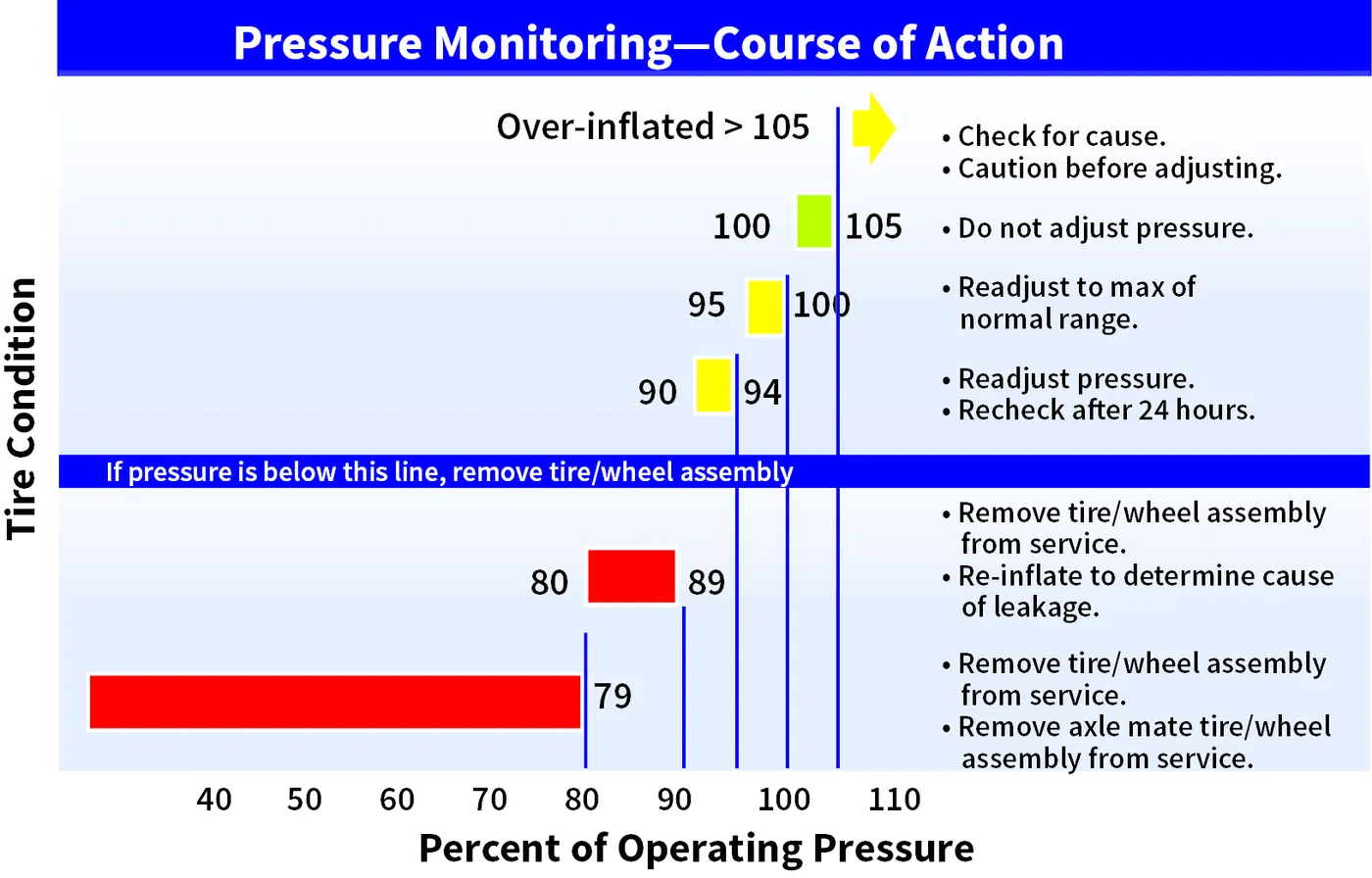
Aircraft tires operate at such high extremes of pressure, load, and speed, their care and service is critically important. The most important action an operator can take to prevent tire-related events is to maintain proper tire inflation pressure.
Aircraft tires are usually inflated with nitrogen to minimize expansion and contraction from extreme changes in ambient temperature and pressure experienced during flight.Dry nitrogen expands at the same rate as other dry atmospheric gases (normal air is about 80% nitrogen),but common compression air source may contain moisture,which increases the expansion rate expansion rate with temperature.
Aircraft tires generally operate at high pressures, up to 200 psi (14 bar; 1,400 kPa) for airliners, and even higher for business jets.
Failure to keep aircraft tires properly inflated can lead to very serious consequences. The most serious of these is the structural failure of the tire. If the tire operates underinflated or overdeflected/overloaded, the nylon cords which form the structure of the tire go in and out of compression as the tire rotates.
Brake forces when Landing:
Aircraft brakes stop a moving aircraft by converting its kinetic energy to heat energy by means of friction between rotating and stationary discs located in brake assemblies in the wheels.Brakes provide this critical stopping function during landings to enable airplanes to stop within the length of the runway.
The brake units are powered by the hydraulics system. An electrical signal is sent from the flight deck to hydraulic actuators near the main landing gear.Here, hydraulic fluid at 3,000 pound per square inch is used to force the brake unit against the wheel, thus slowing it down.
There are two kinds of brakes in an airplane: air brakes and landing brakes. Just like the brakes on a vehicle, the wheels of most airplanes also have brakes. But those can only be used when the plane touches the ground.
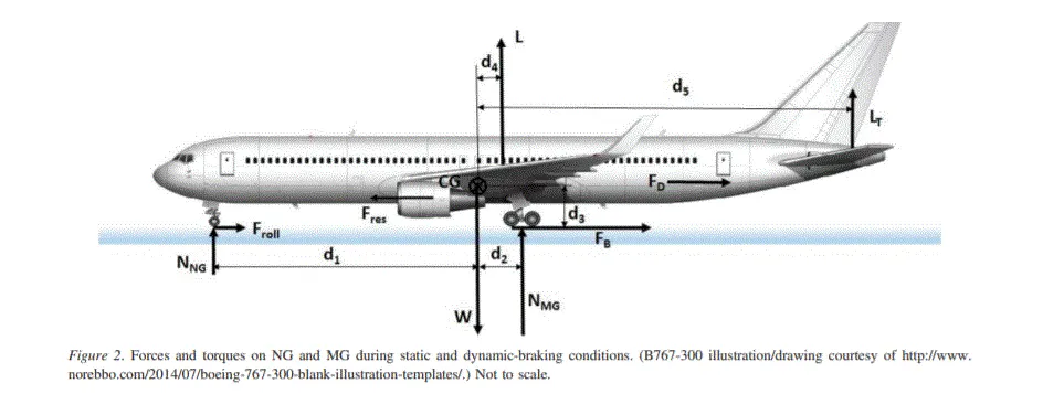
Forces acting on an aircraft after landing are rolling friction force(Froll), drag force(Fd), braking force(Fb), normal reaction of nose gear(Nng), normal reaction of main-gears(Nmg).
PART B :
QA :6
A. With necessary assumptions, calculate the force and power required to push / pull an aircraft by a towing vehicle.
To tow the aircraft we need to overcome 2 forces mainly, they are: (a)Rolling resistance force (b) Aerodynamical force(c) Inertial force
Taking the value of Aircraft 310 specifications are:
Mass= 170000kg
Height= 15.80m
Width= 44.00m
Frontal area A= Height*Width
15.80*44.00=695.2msquare
Drag coefficient Cd=0.0265
Air density = 1.225kg/m square
Taking the value of Towing vehicle TBL280
Mass=40000kg
Height= 2.0m
Width= 3.5m
Frontal area A= Height*Width
2.0*3.5=7m square
Tyre size R=0.5588m
Drag coefficient Cd=0.6
Towing time=18sec
Air density= 1.225kg/m square
Speed v= 32km ph= 32*5/18= 8.89m/s
Now calculate the forces acting on the push and pull
(a)Rolling resistance force
The force to move an airplane on an absolute flat runway with no wind at constant low speed is equal to the rolling resistance between the plane and the tarmac.
Formula
Fr = c*Mr*g
where Fr = rolling resistance(N);c = rolling resistance coefficient;Mr = rolling mass(kg); g= acceleration due to gravity
Fr= 0.02*170000*9.8
Fr=33320N
Now friction force for puller
Ff = μ*W = μ*Mf*g
where Ff = frictional force; Mf = friction mass;μ = coefficient of friction
Consider μ = 0.75
Mf = Ff/(μ*g)=33320/(0.75*9.8)
Mf=4533.3kg
(b) Aerodynamic Force:
This force is acted on the vehicle because the body needs to move through the air. And it depends on frontal area, aerodynamic structure, spoilers, ducts, etc.,
Fad= ½*p*A*Cd*V^2
p= Air density
A= Frontal area
Cd= Drag Coefficient
V= speed
Coefficient of Rolling Resistance urr=0.02
Rolling resistance force of an aircraft Frr= urr*m*g
Rolling Resistance Force of a Towing vehicle Frr2=urr*m*g
Frr= 0.02*35000*9.8= 39004N
Air drag force of an aircraft Fad=½ *p*A*Cd*v^2
=½*1.225*693.62*0.0265*8.89^2
Fad=889.77N.
Now total Force applied by a towing vehicle Ft = Fr + Fad
Ft =(33320+889.77)
Ft=34209.77N
Total Traction Power =34209.77*8.89
=304124.85W
=304.12KW
B) Develop a Simulink Model:
Blocks Used:-
1)Constant
2)Sum
3)Product
4)Square
5)Display
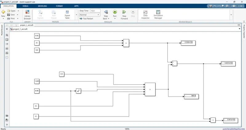
7)
A) Design an electric powertrain with type of motor, its power rating, and energy requirement to fulfill aircraft towing application in Simulink. Estimate the duty cycle range to control the aircraft speed from zero to highest. Make all required assumptions. Prepare a table of assumed parameters. Draw a block diagram of the powertrain.
Based on the calculations done in 6A.
Energy Required
Energy= Power*Time
Power calculated as,
Power= 304.12KW
Time is assumed as 20 minutes which is converter to hours as 0.33h
Time= 0.45h
Now
Energy= 304.12*0.45
Energy= 136.854KWH
Now we have to calculate the input power to the duty cycle of the towing vehicle.
Duty Cycle= Power output/Power input
Input voltage=650V
Input Current= 600A
Power input= Input Voltage*Input Current
Power Input= 650*600=390000W
Power Input= 390KW
Duty Cycle= Power output/Power input
Duty Cycle=304.12/390
Duty Cycle=90%
The duty cycle required for Towing the vehicle is 90%
The Table Represent the assumed Parameters:
Parameters Value
Aircraft
Mass 170000kg
Height 15.80m
Width 44.00m
Air density 1.225 kg/m^2
Towing Vehicle
Mass 40000kg
Height 2.0m
Width 3.5m
Tyre Size 0.5588m
The following figure represent the Block diagram of Powertrain:
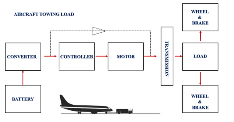
When the battery is to supply the DC voltage to the Converter. The converter gives the required voltage to the controller and the motor is controlled by the controlled block. The output of the motor is given to the transmission system. It is linked to the brakes, wheels and load. We have to design a electric powertrain with type of motor, its power rating and energy requirement to fulfill aircraft towing application.
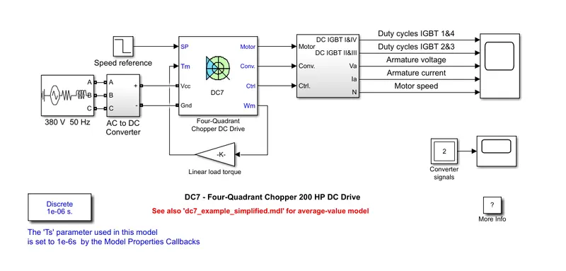
Here AC to DC converter is used because we have taken input as AC so we need to convert it into DC.We have taken supply voltage as 380V. Convert them into DC supply as we are using DC drives. The converter output gives value to the DC7 block which gives value to the selector block.
scope:
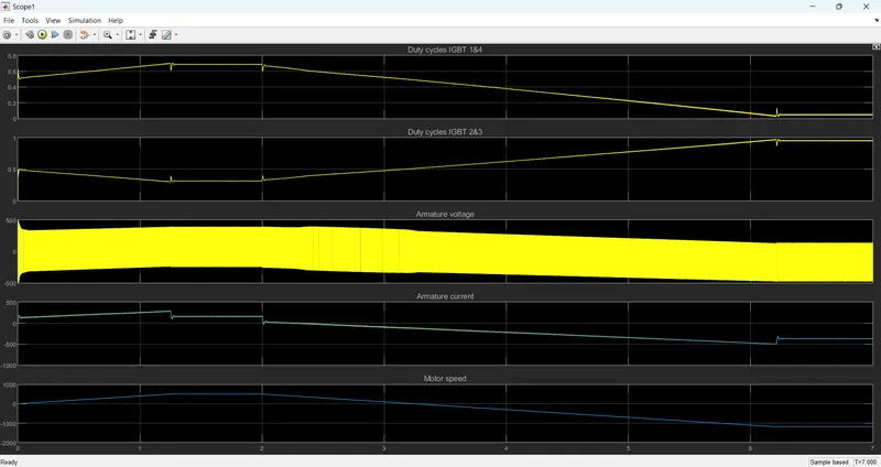
Here we can see the plot for duty cycle, Armature current, Armature voltage, Motor current. Motor reaches its highest voltage and current, Speed then becomes constant and then start decreasing.
B)Design the Parameters in Excel Sheet;
| PARAMETERS | VALUES | ||
| Mass of towing vehicle in kg | 40000 | ||
| Mass of aircraft in kg | 170000 | ||
| Drag coefficient | 0.0265 | ||
| Airdensity in kg/m3 | 1.225 | ||
| Coefficient of rolling resistance | 0.02 | ||
| Gravitation in m/s2 | 9.8 | ||
| Radius of tyre for towing vehicle | 0.5588 | ||
| speed in m/s | 8.89 | ||
| Towing operation time (minutes) | 20 | ||