PROJECT
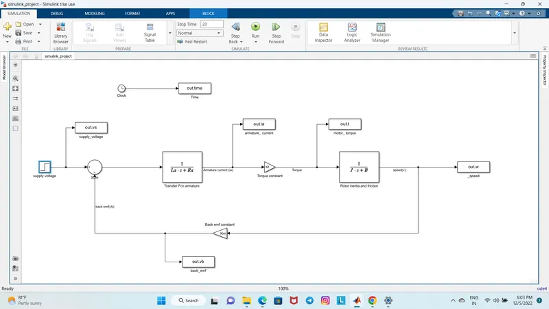
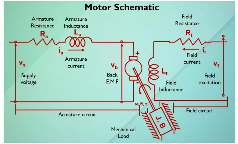
Here a DC motor is being given ,so to find the open loop transfer function for the motor with speed(w) and supply voltage (vs);
Using kirchoffs voltage law:
Vs=RaIa+La*dia/dt +Vb
Back emf,angular velocity and torque are related by :
Vb=Km*derivative of theeta w.r.t time
T=Kti
Here Km and Kt are the back emf and torque constants.
Angular velocity , w=theeta_dot
open loop transfer function for the motor with speed(w) and supply voltage (vs);
w(s)/Vs(s) =Kt/JLas^2+(JRa+BLa)s+(BRa+KtKm)
PID design for speed control of DC motor
Parameters;
*J=moment of inertia of motor -(kgm^2)
*B=Motor viscous friction constant -(Nms)
*Km=Back EMF constant -( v/radians/s)
*Kt=Motor torque constant-( Nm/Ampere)
*Ra=Armature resistance-(ohm)
*La=Armature inductance -(Henry)
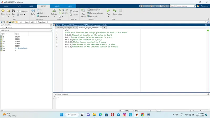
Matlab script
clc
close all
%This file contains the design parameters to model a D.C motor
J=0.01;%Moment of inertia of the rotor in kgm^2
B=0.1;%Motor viscous friction constsnt in N-m-s
Km=0.01;%Back emf constant in v/rad/s
Kt=0.01;%Motor torque constant in N-m/amp
Ra=1.0;%Resistance of the armature circuit in ohms
La=0.5;%Inductance of the armature circuit in henries
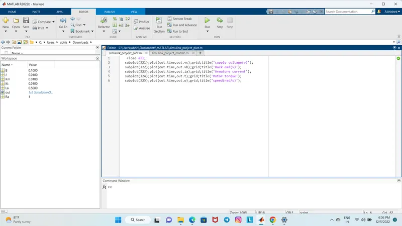
close all;
subplot(321);plot(out.time,out.vs);grid;title('supply voltage(v)');
subplot(322);plot(out.time,out.vb);grid;title('Back emf(v)');
subplot(323);plot(out.time,out.ia);grid;title('Armature current');
subplot(324);plot(out.time,out.t);grid;title('Motor torque');
subplot(325);plot(out.time,out.w);grid;title('speed(rad/s)');
Design of DC motor :
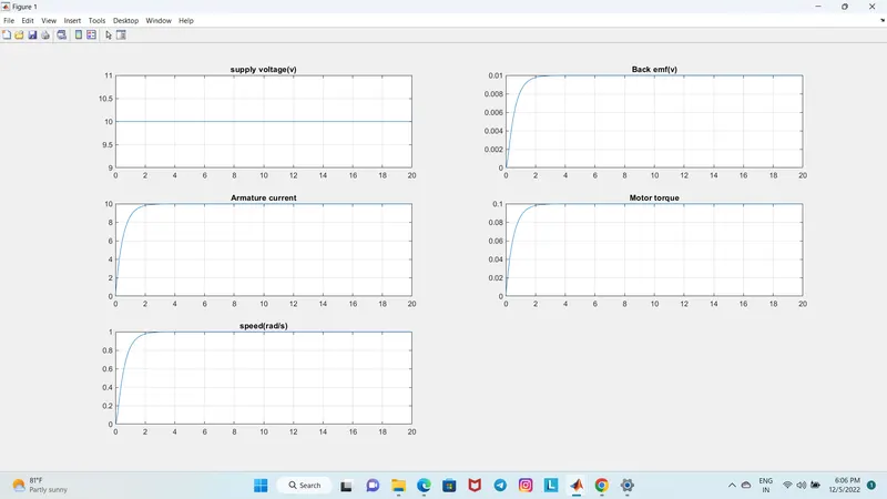
* without using PID controller
Design of DC motor :
*Using PID controller
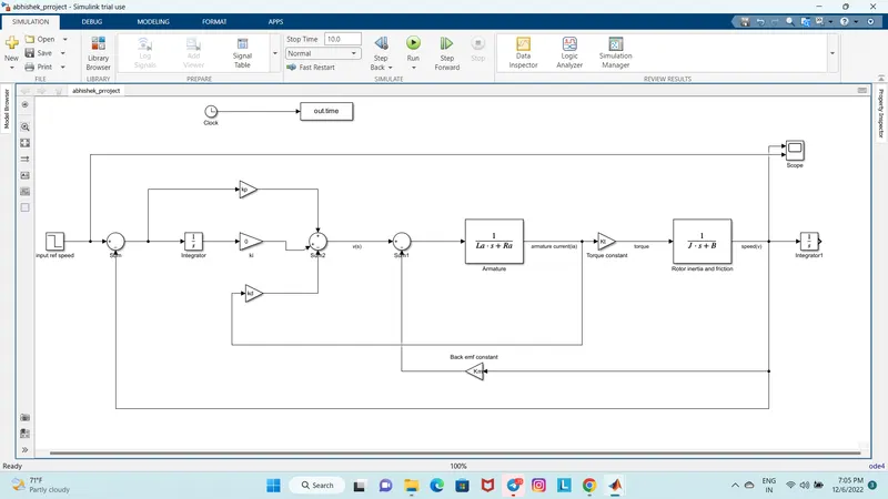
To design a closed loop control scheme for a DC motor the following changes need to be done in the previous model;
*speed is the contollable parameter ,so we will set the reference speed in step block as 40,10,5,1 .
*subtract the actual speed from the reference speed to generate the error signal e(t).
*Use gain block to mention values of kp,kd and ki.
*The feedback for kd is provided from the output current of the plant/model. or we can take the feedback (error speed signal as input to kd).
*Add ki manually with gain and integrator block and take different values of ki such as 0,30 and 35 and check the impacts of it on results.
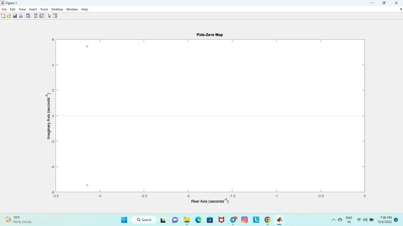
To check the location of poles on s-plane we can use 'pzmap'.We can see two crosses in red indicate complex poles lying on left hand of the plane which indicate it is a stable system.
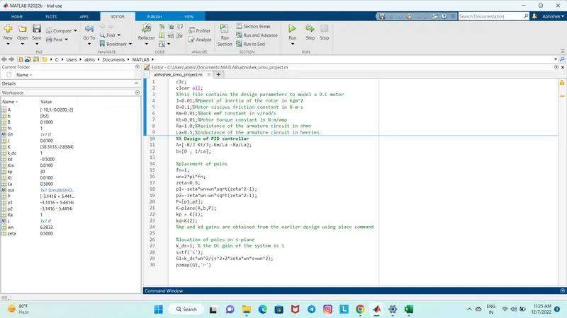
Matlab script:
clc;
clear all;
%This file contains the design parameters to model a D.C motor
J=0.01;%Moment of inertia of the rotor in kgm^2
B=0.1;%Motor viscous friction constsnt in N-m-s
Km=0.01;%Back emf constant in v/rad/s
Kt=0.01;%Motor torque constant in N-m/amp
Ra=1.0;%Resistance of the armature circuit in ohms
La=0.5;%Inductance of the armature circuit in henries
%% Design of PID controller
A=[-B/J Kt/J;-Km/La -Ra/La];
b=[0 ; 1/La];
%placement of poles
fn=1;
wn=2*pi*fn;
zeta=0.5;
p1=-zeta*wn+wn*sqrt(zeta^2-1);
p2=-zeta*wn-wn*sqrt(zeta^2-1);
P=[p1;p2];
K=place(A,b,P);
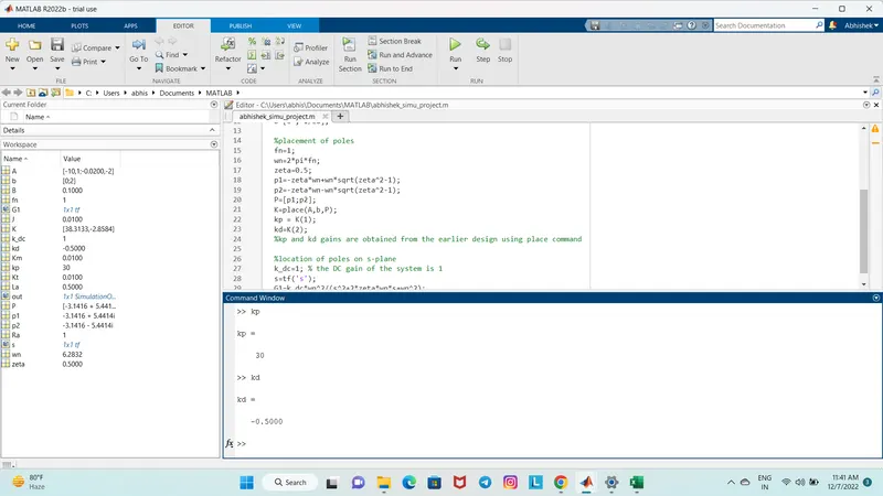
kp = K(1);
kd=K(2);
%kp and kd gains are obtained from the earlier design using place command
%location of poles on s-plane
k_dc=1; % the DC gain of the system is 1
s=tf('s');
G1=k_dc*wn^2/(s^2+2*zeta*wn*s+wn^2);
pzmap(G1,'r')
SIMULINK BASED MODEL OF ABOVE SCHEMATIC DIAGRAM
Pole - zero mapping on s-plane:
* Since the poles are located on the left half plane we can say that the system is stable.
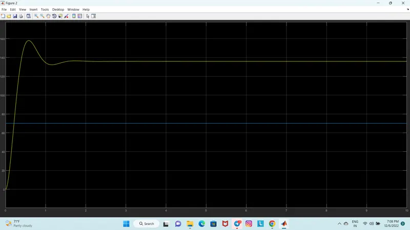
Case 1:
Ref signal(Step)
step time:40
initial value:40
final value:0
ki=0
kp=38.313
kd=-2.8584
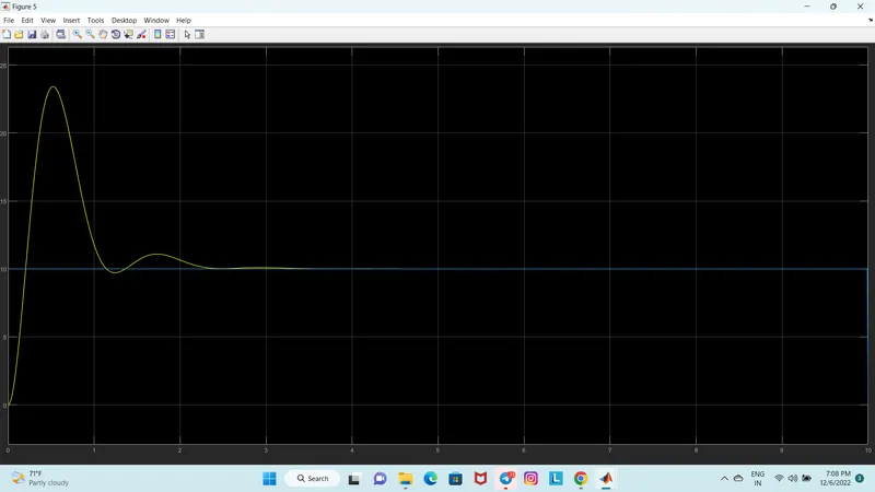
Case 2:
Ref signal(Step)
step time:10
initial value:10
final value:0
ki=30
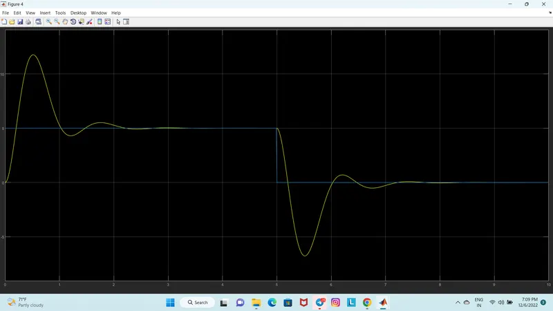
Case 3:
Ref signal(Step)
step time:5
initial value:5
final value:0
ki=35
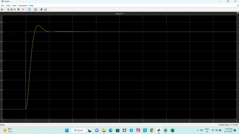
Case 4:
Ref signal(Step)
step time:1
initial value:0
final value:40
CONCLUSION :
From the given cases we can see that as the value of ki,kp and kd are changed the scope for the speed provides undershoot,overshoot and steady state response.And by changing the values of step time,initila value and final value of the input reference signal ie the step block also changes control the output final speed waveform.As we can see in the last case 4 as the ki value was kept 32 ,kp as 30 and kd as -0.5 we got a desired speed output with less overshoot and undershoot compared to the other 3 cases.So by controlling the values in a PID controller we can maintain a desired speed for the motor.