Project-1: Powertrain for aircraft in runways
1. Search and list out the total weight of various types of aircrafts.
Sol: Below list contains the top 15 types of aircrafts based on MTOW & MLW.
Here, MTOW = Maximum take-off weight, MLW = Maximum landing weight.
| Type | MTOW (kg) | MLW (tonnes) |
| Antonov An-225 | 640,000 | 591.7 |
| Scaled Composites Model 351 Stratolaunch | 589,670 | N/A |
| Airbus A380-800 | 575,000 | 394 |
| Boeing 747-8F | 447,700 | 346.091 |
| Boeing 747-8 | 443,613 | 306.175 |
| Boeing 747-400ER | 412,770 | 295.742 |
| Antonov An-124-100M | 405,060 | 330 |
| Boeing 747-400 | 396,900 | 295.742 |
| Lockheed C-5 Galaxy | 381,000 | 288.417 |
| Boeing 747-200 | 377,840 | 285.700 |
| Boeing 747-300 | 377,840 | 260.320 |
| Airbus A340-500 | 371,950 | 240 |
| Airbus A340-600 | 367,400 | 256 |
| Boeing 777F | 347,800 | 260.816 |
| Boeing 777-300ER | 351,800 | 251.29 |
____________________________________________________________________________
2. Is there any difference between ground speed and air speed?
Sol: Yes there is a difference between ground speed and air speed and is as explained below:
Ground Speed
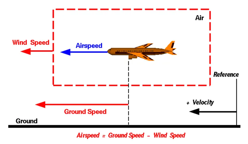
For a reference point picked on the ground, the aircraft moves relative to the reference point at the ground speed. Ground speed is also a vector quantity so a comparison of the ground speed to the wind speed must be done according to rules for vector comparisons.
Wind Speed
For a reference point picked on the ground, the air moves relative to the reference point at the wind speed. Notice that the wind speed is a vector quantity and has both a magnitude and a direction. Direction is important. A 20 mph wind from the west is different from a 20 mph wind from the east. The wind has components in all three primary directions (north-south, east-west, and up-down). In this figure, we are considering only velocities along the aircraft's flight path. A positive velocity is defined to be in the direction of the aircraft's motion. We are neglecting cross winds, which occur perpendicular to the flight path but parallel to the ground, and updrafts and downdrafts, which occur perpendicular to the ground.
Airspeed
The important quantity in the generation of lift is the relative velocity between the object and the air, which is called the airspeed. Airspeed cannot be directly measured from a ground position, but must be computed from the ground speed and the wind speed. Airspeed is the vector difference between the ground speed and the wind speed.
Airspeed = Ground Speed - Wind Speed
On a perfectly still day, the airspeed is equal to the ground speed. But if the wind is blowing in the same direction that the aircraft is moving, the airspeed will be less than the ground speed.
Example
Suppose we had an airplane that could take off on a windless day at 100 mph (liftoff airspeed is 100 mph). We are at an airport with an east-west runway that is 1 mile long. The wind is blowing 20 mph towards the west and the airplane takes off going east. The wind is blowing towards the aircraft which we call a headwind. Since we have defined a positive velocity to be in the direction of the aircraft's motion, a headwind is a negative velocity. While the plane is sitting still on the runway, it has a ground speed of 0 and an airspeed of 20 mph:
Airspeed = Ground Speed (0) - Wind Speed (-20) = 20 mph
The airplane starts its take off roll and has a constant acceleration a. From Newton's second law of motion, the ground speed V at any time t is:
V = a * t
and the distance d down the runway at any time is:
d = 1/2 * a * t^2
For a fixed length runway, this specifies the time to be used in the velocity equation. Let's assume that at 5000 feet down the runway, the velocity is 80 mph. Then the airspeed is given by
Airspeed = Ground Speed (80) - Wind Speed (-20) = 100 mph
and the airplane begins to fly. Now another pilot, with exactly the same airplane decides to take off to the west. The wind is now in the same direction as the motion and this is called a tailwind. The sign on the wind speed is now positive, not negative as with the headwind. The acceleration along the ground is the same, so at 5000 feet down the runway, the ground speed is again 80 mph. The airspeed is then given by:
Airspeed = Ground Speed (80) - Wind Speed (20) = 60 mph
This airplane doesn't have enough airspeed to fly. It runs off the end of the runway!
____________________________________________________________________________
3. Why is it not recommended to use aircraft engine power to move it on the ground at Airport?
Sol: Pushback means the movement of an aircraft from a nose-in parking stand using the power of a specialised ground vehicle attached to or supporting the nose landing gear. It is commonly the second part of a ‘Taxi In Push Out’ (TIPO) procedure at airport terminal gates and will be necessary to depart from all except self manoeuvring parking stands unless the aircraft type is capable of powerback and local procedures allow this. Occasionally, a pushback may need to be followed by an engines-running pull forward to a position where local procedures allow aircraft to move forward under their own power, but usually, ground vehicle disconnection will occur after the completion of a pushback.
Pushback using the jet-engine's thrust reverser is a highly fuel-consuming and noisy process and also potentially hazardous for personnel working near the plane. Although many aircrafts are capable of moving themselves backwards on the ground using reverse thrust, the resulting jet-blast or prop wash might casue damage to the terminal building or equipment.
Engines close to the ground may also blow sand and debris forward and then suck them into the engine. A pushback is therefore the preferred method to move the aircraft from the terminal.
Once the flight is tugged off to a safe distance from the terminal the plane begins to use it's own engine power for the rest of the taxing process.
____________________________________________________________________________
4. How an aircraft is pushed to runway when its ready to take off?
Sol: Pushbacks using Tugs:
Pushbacks at busy aerodromes are usually subject to ground control clearance to facilitate ground movements on taxiways. Once clearance is obtained, the pilot will communicate with the tractor driver (or a ground handler walking alongside the aircraft) to start the pushback. To communicate, a headset may be connected near the nose gear.
Since the pliots cannot see the rear of the aircraft, steering is done by the push back tractor driver and not by the pilots.
Depending on the aircraft type and airline procedure, a bypass pin maybe temporarily installed into the nose gear to disconnect it from the aircraft's normal steering mechanism.
Once the pushback is completed, the towbar is disconnected, and any bypass pin removed.
The ground handler will show the bypass pin to the pilots to alert the pilots that it has been removed.
The pushback is completed and the aircraft can taxi forward under its own power now.
____________________________________________________________________________
5. Learn about take off power, tyre design, rolling resistance, tyre pressure, brake forces when landing.
Sol:
a) Take off Power:
On take-off, in order to position the aircraft to a safe height away from terrain and obstacles (i.e. a flight path of maximum height and minimum ground distance desired), the engine thrust is set to a high ‘take-off power’ setting (although this is not necessarily full power) and the aircraft attitude is pitched up to maintain a specific speed (usually in the region of V2 + 15kts). Once the ‘safe height’ is reached the engine thrust can therefore be reduced to a more appropriate (i.e. efficient) setting and the aircraft flight path can be changed to a more appropriate (i.e. efficient) flight path.
For light aircraft, usually full power is used during takeoff. Large transport category (airliner) aircraft may use a reduced power for takeoff, where less than full power is applied in order to prolong engine life, reduce maintenance costs and reduce noise emissions. In some emergency cases, the power used can then be increased to increase the aircraft's performance.
Fixed-wing aircraft designed for high-speed operation (such as commercial jet aircraft) have difficulty generating enough lift at the low speeds encountered during takeoff. These are therefore fitted with high-lift devices, often including slats and usually flaps, which increase the camber and often area of the wing, making it more effective at low speed, thus creating more lift. These are deployed from the wing before takeoff, and retracted during the climb. They can also be deployed at other times, such as before landing.
b) Tyre Design:
Two types of tyres are used in aircraft applications — bias-ply tyres and radial tyres. Although both types of tyres share some similarities in design, there are differences that need to be noted.
Bias-ply tyre construction
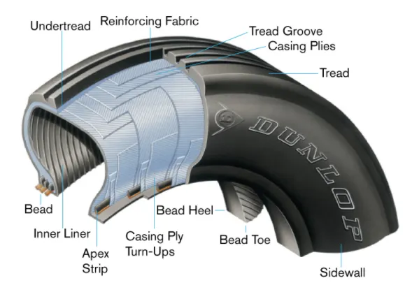
A cutaway of a typical bias-ply tyre is shown in above figure. Bias-ply tyres are popular choices for aircraft tyres because of their durability and retreadability. The tyre construction consists of the following components:
Tread: The tread is made of rubber mixed with other additives to obtain the desired level of toughness, durability, and resistance to wear. The tread pattern is designed to aircraft operational requirements, with the ribbed tread design used widely due to its good traction under varying runway conditions.
Sidewall: The sidewall is a protective layer of rubber that covers the outer casing ply. It extends from the tread edge to the bead area.
Tread Reinforcing Ply: One or more layers of fabric that strengthens and stabilizes the tread area for high-speed operation. It also serves as a reference for the buffing process when tyres are retreaded.
Buff Line Cushion: The buff line cushion is made of rubber compound to enhance the adhesion between the tread reinforcing ply and the breakers or casing plies. It is of sufficient thickness to allow for the removal of the old tread when the tire is retreaded.
Breakers: Breakers are reinforcing plies of rubber-coated fabric placed under the buff line cushion to protect casing plies and strengthen and stabilize the tread area. They are considered an integral part of the casing construction.
Casing Plies: Alternate layers of rubber-coated fabric (running at opposite angles to one another) provide the strength of the tyre.
Wire Beads: Hoops of high tensile strength steel wire that anchor the casing plies and provide a firm mounting surface on the wheel. The outer edge of the bead that fits against the wheel flange is called the bead heel. The inner bead edge is called the bead toe.
Apex Strip: A wedge of rubber affixed to the top of the bead bundle.
Flippers: Layers of rubberized fabric that help anchor the bead wires to the casing and improve the durability of the tyre.
Ply Turnups: The casing plies are anchored by wrapping them around the wire beads, thus forming the ply turnups.
Chafer: A protective layer of rubber and/or fabric located between the casing plies and wheel to minimize chafing.
Liner: In tubeless tyres, the liner is a layer of low permeability rubber that acts as a built-in tube and restricts gas from diffusing into the casing plies. In tube-type tyres, a thinner liner is used to prevent tube chafing against the inside ply.
Radial-ply tyre construction
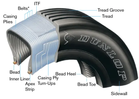
A typical radial tyre is illustrated in Figure 2. With their rigid belt, they provide increased landings and reduced rolling resistance. They have fewer components in their construction and are lighter than similarly sized bias ply tyres. Components that differ from bias-ply construction as follows:
Overlay: A layer of reinforcing rubber coated fabric placed on top of the belts to aid in high speed operation.
Belt Plies: A composite structure that stiffens the tread area for increased landings. The belt plies increase the tyre strength in the tread area.
Casing Plies: As in bias-ply tyres, the casing plies are layers of rubber-coated fabric. However, unlike those in bias plies that run at opposite angles to one another, radial plies run radially from bead to bead.
Chippers: The chippers are layers of rubber-coated fabric applied at diagonal angles that improve the durability of the tyre in the bead area.
Tyre inspection
In order to ensure safety and increase tyre life, systematic inspections of mounted tyres should be performed. A word of warning — Never probe cracks, cuts, or embedded foreign objects while the tyre is inflated! Serious injuries could result. In addition, defects such as cuts, cracks, and bulges should be marked with a crayon or chalk prior to deflation since the defects may disappear when the tyre is deflated. The following should be checked:
Tread wear: Treads should be visually inspected for wear. The tyre should be replaced when tread has worn to the base of any groove at any spot or to a minimum depth specified in the aircraft maintenance manual. Tread wear can also be an indication of improper tyre inflation. Refer to Figure 3 for tread wear indications.
Tread cuts: The tyre should be inspected for cuts and other foreign damage. Follow the criteria from the applicable aircraft maintenance manual. If no specific criteria is outlined in the manual, the following can be used for guidance in determining tread cuts:
A-Normal
Even tread wear on this tire indicates that it has been properly maintained and run at correct inflation pressure.
B-Excessive
Worn to the breaker/casing plies, the tire should not be left in service or retreaded.
C-Overinflation
Continuous overinflation accelerates center tread wear. It reduces traction while making tread more susceptible to cutting.
D-Underinflation
Excessive tread shoulder wear results from chronic underinflation. It increases the chance of damaging shoulders and sidewalls which shortens tire life because of excessive flex heating.
• Any cut that extends into the casing plies on bias tyres.
• Any cut into the belt on radial tyres.
• Any cut that extends across one or more rubber tread ribs to the fabric.
• Rib undercutting at the base of any
cut or tread splice warrants replacement.
c) Rolling Resistance:
Rolling resistance, sometimes called rolling friction or rolling drag, is the force resisting the motion when a body (such as a ball, tire, or wheel) rolls on a surface. It is mainly caused by non-elastic effects; that is, not all the energy needed for deformation (or movement) of the wheel, roadbed, etc., is recovered when the pressure is removed. Two forms of this are hysteresis losses , and permanent (plastic) deformation of the object or the surface (e.g. soil). Another cause of rolling resistance lies in the slippage between the wheel and the surface, which dissipates energy. Note that only the last of these effects involves friction, therefore the name "rolling friction" is to an extent a misnomer.
The "rolling resistance coefficient" is defined by the following equation:[5]

- where
 is the rolling resistance force,
 is the dimensionless rolling resistance coefficient or coefficient of rolling friction (CRF), and
 is the normal force, the force perpendicular to the surface on which the wheel is rolling.
The rolling resistance for an aircraft depends upon factors such as aircraft weight, runway condition, tyre conditions, tyre pressure, environmental factors (such as weather conditions etc.).
d) Tyre Pressure:
An aircraft tire or tyre is designed to withstand extremely heavy loads for short durations.The number of tires required for aircraft increases with the weight of the aircraft, as the weight of the airplane needs to be distributed more evenly. Aircraft tire tread patterns are designed to facilitate stability in high crosswind conditions, to channel water away to prevent hydroplaning, and for braking effect.
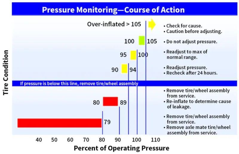
Aircraft tires generally operate at high pressures, up to 200 psi (14 bar; 1,400 kPa) for airliners, and even higher for business jets. Tests of airliner aircraft tires have shown that they are able to sustain pressures of maximum 800 psi (55 bar; 5,500 kPa) before bursting.
e) Brake Forces on landing:
Bringing an aircraft to a safe stop is the most important part of a flight. In order to do this, pilots have a number of facilities available to them. The brakes bear the brunt of the hard work with the spoilers and reverse thrust lending a helping hand to ensure maximum efficiency.
The autobrake system helps keep the deceleration nice and smooth whilst the anti-skid system reduces the distances needed to stop by modulating the brakes on individual wheels and stopping them from skidding.
Aircraft can also depart with part of the braking system not working.
By carrying out a performance calculation before every takeoff and landing, we ensure that the aircraft will stop safely in the given conditions, even at maximum takeoff weight.
____________________________________________________________________________
6. With necessary assumptions, calculate the force and power required to push / pull an aircraft by a towing vehicle.
Sol:
i) Rolling Resistance Force:
Frr = μrr * m * g
where, m * g = Weight in Newtons
μrr = Coefficient of rolling resistance
Weight of aricraft = 59400 kg
Rolling resistance coefficient of aircraft = 0.006
Weight of towing tractor = 7620 kg
Rolling resistance coefficient of towing tractor = 0.01
Now, Rolling Resistance force of Towing tractor = 0.001 * 7620 * 9.81
= 747.522 N
Rolling Resistance force of aircraft = 0.006 * 59400 * 9.81
= 3496.284 N
Therefore, total Rolling resistance force = 747.522 + 3496.284
= 4243.806
ii) Air drag Force:
Aerodynamic drag force, Fad = 0.5 * ρ * A * V^2 * Cd
where, ρ = Density of air medium = 1.225 kg / m^3
A = Frontal area of aircraft = 2 m^2
V = velocity of aircraft while towing = 4.5 m/s
Cd = Coefficient of drag of aircraft = 0.25
Now, Air drag Froce = 0.5 * 1.225 * 2 * 4.5^2 * 0.25
= 6.17 N
Total Force Required = Rolling Resistance Force + Air Drag Force
= 4243.806 + 6.17
= 4249.98 N
Assuming the wheels of the tug are 17.5 inches (0.4445m) in diameter, then the torque required by the tug is:
Torque required by the tug to push the aircraft = Force * radius
= 4249.98 * 0.4445
= 1889.11 Nm
Power Required:
P = Total forces * velvocity
= 4249.98 * 4.5
= 19.12 kW
____________________________________________________________________________
7. Design an electric powertrain with type of motor, it’s power rating, and energy requirement to fulfill aircraft towing application. Estimate the duty cycle range to control the aircraft speed from zero to highest. Make all required assumptions. Prepare a table of assumed parameters. Draw a block diagram of powertrain.
Sol: We know electric Powertrain has three mani components:
Battery -------> Power Converter -------> Motor
First motor ratings is calculated, then power converter ratings are calculated and finally battery capacity is calculated.
Motor Design:
Torque calculation
The Electric Tug is assumed to have a gear ratio of 1:10. Thus the torque produced by motor is multiplied by a factor 10 at wheels.
Torque required at the wheels of the Tug to pushback the aircraft = 1889.11 Nm (from previous question)
Required motor torque = 1889.11 /10 = 188.9 Nm (Assuming there are no transmission losses)
Assumtions made
motor loss = 10%
Transmission losses = 20%
Required motor torque = 188.9 + 188.9(0.1+0.2)
= 245 Nm
Power calculation
The power required = 19.12 kW (from previous question)
Assumptions made:
Motor efficiency = 90%
Motor is designed to run at 80 % of the full load capacity for safety purposes.
Required Motor Power = 19.12 / (0.9 * 0.8)
= 26.5 kW or 35.56 HP
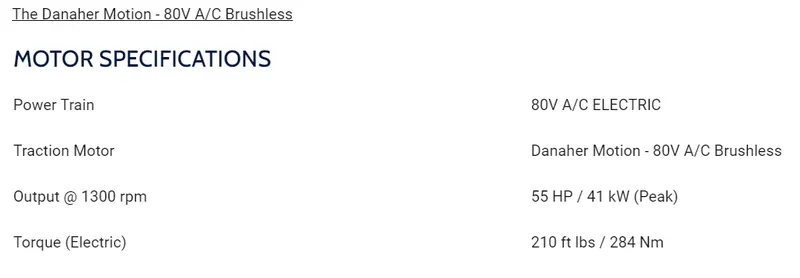
Thus we choose the following motor which match our requirements:
Power Converter:
Required Power is 26.5 kW & motor's full rated power is 41 kW.
Thus a DC-AC converter such as sine wave inverter with 41 kW handling capacity is chosen.
Duty cycle = 26.5/41 = 0.64.
The duty cycle range is from 0 to 64 %.
Battery Capacity:
Assuming an avergae taxing time for E-195 aircraft is about 10 minutes. The energy required to move the aircraft for 10 minutes is calculated Time = 10 mins (600 seconds)
Energy = power*time*60
= 26.5*10*60
= 15900 KJ
= 15.900 MJ or 4.4167 kWh
= 4.4167 kWh
Thus for operating the Tug for 10 minutes to tow one aircraft the energy required is 4.4 kWh.
Apart from towing the aircraft, the Tug should move from its parking place to tow the aircraft and then comeback from runway to parking place. To accomodate this travel an
additional 0.6 kWh is added to required energy.
Thus for single towing opertaion the energy required is 4.4 kWh + 0.6 kWh = 5.0 kWh.
This is the energy required for sinlge opertaion. Assuming a single full charge of battery the Tug can perform 25 Towing operations. The required battery capacity is = 5.0 kWh * 25 = 125 kWh.
Electric Powertrain Required:
Motor Specifications: Torque - 245 Nm & Power - 19.12 kW ( Chosen Motor specifications -Torque = 284 Nm & power = 41kW (Peak))
Power Inverter Specifications : Duty cycle range - 0 to 64 % and handling capacity 41 kW
Battery Capacity = 125 kWh.
____________________________________________________________________________