Week-7 Challenge: DC Motor Control
1. Run MATLAB demo ‘Speed control of a DC motor using BJT H-bridge’. Modify the model such that armature current doesn’t shoot up when motor changes direction from forward to reverse.
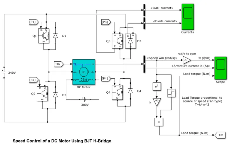
Sol: The following image shows the Simulink model:
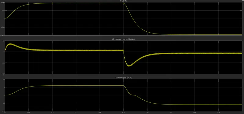
i) At 75% duty cycle:
Here the motor starts in the positive direction with a duty cycle of 75%. At 0.5 sec, the armature voltage is suddenly reversed and the motor runs in negative direction. We get the following plot with 75% duty cycle
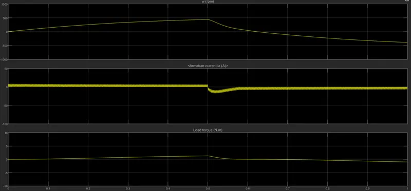
ii) At 50% Duty Cycle:
In this case the duty cycle is reduced to 50% and we can observe here that the armature current doesnot shoot up initially in the positive directionof the armature voltage. However, after 0.5 sec mark when the armature voltage is reversed, the armature current shoots up from the negative direction. So to prevent this behavior, we need to decrease the duty cycle further. The behavior of 50% duty cycle is shown below:
iii) At 40% Duty Cycle:
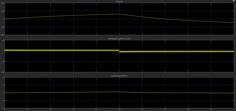
In the above pic we can see that the armature current doesnot shoot up like it did before. Here there is a smooth transition from positive to negative direction of armature current.
___________________________________________________________________________________
2. Refer to help section of ‘The Four-Quadrant Chopper DC Drive (DC7) block’. Compare it with H-bridge model.
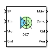
Sol: The Four-Quadrant Chopper DC Drive (DC7) block represents a four-quadrant, DC-supplied, chopper (or DC-DC PWM converter) drive for DC motors. This drive features closed-loop speed control with four-quadrant operation. The speed control loop outputs the reference armature current of the machine. Using a PI current controller, the chopper duty cycle corresponding to the commanded armature current is derived. This duty cycle is then compared with a sawtooth carrier signal to obtain the required PWM signals for the chopper. The image below shows a DC7 block:
The main advantage of this drive, compared with other DC drives, is that it can operate in all four quadrants (forward motoring, reverse regeneration, reverse motoring, and forward regeneration). In addition, due to the use of high switching frequency DC-DC converters, a lower armature current ripple (compared with thyristor-based DC drives) is obtained. However, four switching devices are required, which increases thecomplexity of the drive system. The detailed circuit diagram of a DC7 block is as shown below:
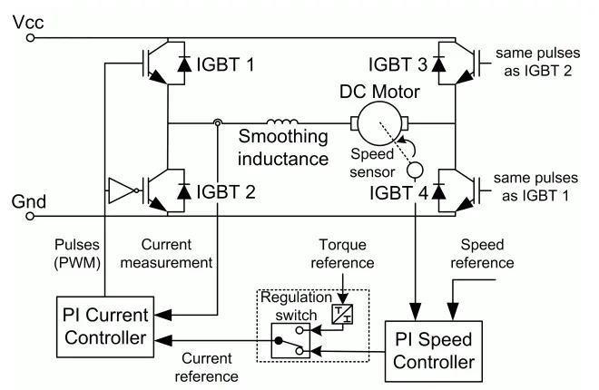
The Four-Quadrant Chopper DC Drive block uses these blocks from the Electric Drives/Fundamental Drive Blocks library:
-
Speed Controller (DC)
-
Regulation Switch
-
Current Controller (DC)
-
Chopper
Comparison to H-Bridge
Both BJT H-bridge & 4 quadrant choppers have their pros and cons. H-bridges like the 4 quadrant choppers are capable of braking operation without using air resistance or friction/physical brakes to slow the motor down. 4 quadrant DC choppers are more commonly used in automobiles whereas BJT H-bridges are used in robotics & electro-mechanical devices.
BJT H-bridges are not capable of performing regenrative braking but they can perform dynamic braking. This makes the 4 quadrant DC choppers more useful in Hybrid or Electric vehicles.
The current signals in 4 quadrant DC choppers are chopped meaning that they are not continuous, hence the simulations take much less time than the BJT H-bridges in which the current values are not chopped and are continuous.
In 4 quadrant DC Chopper, a PI controller is used to control the speed and the current and in H-bridge this is not implemented.
_____________________________________________________________________________
3. Make a suitable EV model using DC7 block and make result report.
Sol: For this study, i have considered DC7 block example available in MATLAB Documents.
Following is the modified circuit diagram for EV with DC7 block:
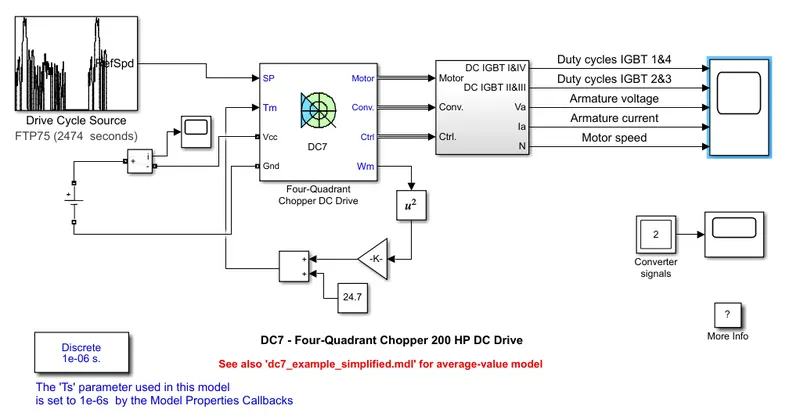
Here the drive cycle input is considered as the FTP75 drive cycle and the cycle time is considered as 100 seconds. The drive cycle is connected with the 'SP' terminal of the DC chopper.
The developments done to the system are as follows:
1) I have replaced the default supply blocks of the DC7 model with a constant voltage DC Supply. The positive side of DC Supply is connected with a 'current measurement' block and the negative terminal of this 'current measurement' block is then connected to the 'Vcc' terminal of DC chopper and negative side of DC supply is connected with 'Gnd' terminal of DC chopper. The DC Voltage source considered is 200V.
2) For this model I have considered an equation that characterizes the relation between Torque and speed as below:
Tm = 0.0051ω^2 + 24.7 ... (i)
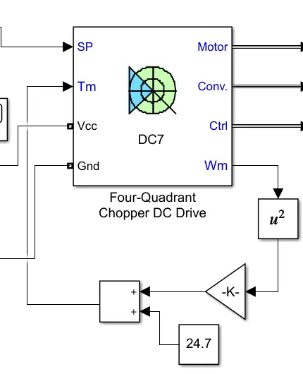
So the Linear Load Torque block is replaced by a combination of blocks as shown in below image:
a) Math Function block:

Here the function is set as square in the parameters.
b) Gain Block:

The math function block is connected with 'Gain' block to multiply the squared angular speeds with a coefficient 0.0051 as need in the Torque-Speed equation (as per (i)). The 'Gain' block is modified with a value of 0.0051.
c) Constant Block:

The constant block is fed with the value 24.7.
d) Add Block:

The gain block and the constant block are connected together using an 'Add' block. The 'Add' block is then connected to the 'Tm' terminal of the DC chopper block.
RESULT:
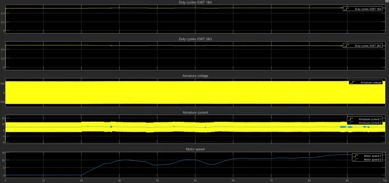
Hence we have simulated the motor speed, armature current and armature voltage using the FTP75 drive cycle and the behavior have been plotted in the above graph.
____________________________________________________________________________