Project-1: Powertrain for aircraft in runways
OBJECTIVES
The following studies need to be completed for this project:
- Find and list all of the different types of aircraft's overall weight.
- Is there a difference between air speed and ground speed?
- Why is it not recommended to move it on the airport's ground using an aircraft's engine power?
- How is a plane pushed onto the runway when it is time to take off?
- Learn about the force required to brake upon landing, takeoff power, tyre design, rolling resistance, and tyre pressure.
- Calculate the force and power necessary to push or pull an aeroplane with the appropriate assumptions.
- Create an electric powertrain using the type of motor, the motor's power rating, and the amount of energy needed to complete the aircraft towing application. Calculate the range of duty cycles needed to control the aircraft's speed from zero to maximum. Make all necessary assumptions. Create a table with the factors that put parameters. Make a block diagram of the drivetrain.
PART A
1.List all of the different types of aircraft's overall weight.
The overall weight of the aircraft at any point during a flight or ground operation is known as the aircraft gross weight (sometimes referred to as the all-up weight and abbreviated as AUW). Due to the consumption of fuel and lubrication, an aircraft's gross weight will drop during a flight. The gross weight of an aircraft may change throughout a flight as a result of payload loss or in-flight refuelling.
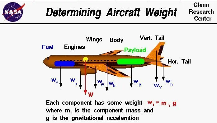
Maximum ramp weight(MRW)
It is referred to as the highest weight permitted for towing or taxiing on the ground, as permitted by the strength or airworthiness criteria of the aircraft. The size of the aircraft, the number of engines, the operation of the APU, and engine fuel consumption all affect the difference between the maximum ramp weight and the maximum take-off weight. They are normally estimated to take 10 to 15 minutes, including taxiing, towing, and run-up procedures.
Maximum take-off weight(MTOW)
It is referred to as the maximum certified design weight for a takeoff run, based on the limitations of aircraft strength and aviation safety. To accommodate for fuel burnt during taxi by the engines and the APU, the maximum take-off weight is always less than the maximum ramp weight.
Maximum landing weight(MLW)
It is described as the maximum design certified weight for an aircraft's typical landing. It mostly depends on the strength of the landing gear or the impact loads of the landing on certain components of the wing and chassis construction.
MZFW, or maximum zero fuel weight
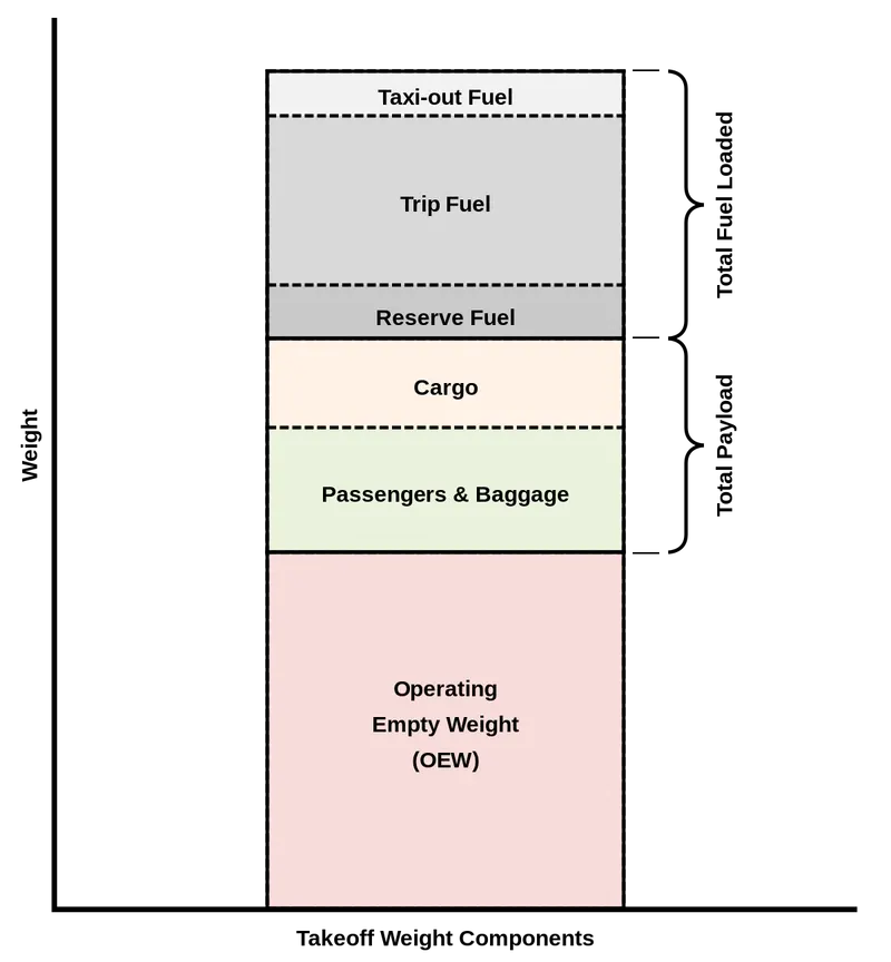
The maximum certified weight of an aircraft without usable fuel and other restrictions imposed by the aircraft's strength and aviation safety is known as its maximum zero fuel weight. In other words, it is the maximum weight allowed before the aircraft is filled with useful fuel and other cargo.
Operational Empth Weight (OEW)
The OEW is set for a particular aircraft and is only modified for operational and maintenance purposes. The empty weight, or OEW, is the measure used in flight simulators or standard planning software.
AZFW, or actual zero fuel weight
The true zero fuel weight is obtained by adding the cargo to the empty plane weight. Basically, the payload consists of the combined weight of the cargo and passenger bags according to the following relationship.
Minimum Flight weight(MFW)
According to restrictions on aircraft strength and aviation safety, the minimum certified weight for flying. Empty weight with payload is included in an aircraft's overall weight.
Aircrafts's empty weight
The aircraft's weight, including the amount of gasoline and other working fluids still in the tank.
Payload
The weight of the working fluids added weight of the passengers and fuel.
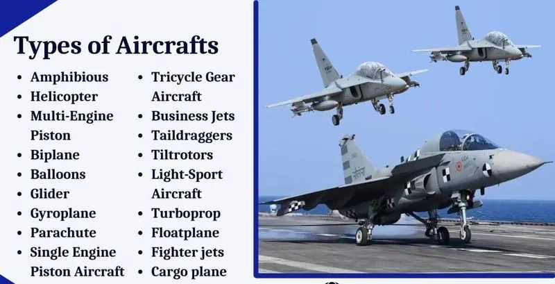
Some Aircraft lists are mentioning below
MTOW-Maximum Take off weight
MLW-Maximum Landing Weight
| Type | MTOW [kg] | MLW [tons] |
| Antonov An-225 | 640,000 | 591.7 |
| Scaled Composites Model 351 Stratolaunch | 589,670 | |
| Airbus A380-800[1][2] | 575,000 | 394 |
| Boeing 747-8F | 447,700 | 346.091 |
| Boeing 747-8 | 443,613 | 306.175 |
| Boeing 747-400ER | 412,770 | 295.742 |
| Antonov An-124-100M | 405,060 | 330 |
| Boeing 747-400 | 396,900 | 295.742 |
| Lockheed C-5 Galaxy[3][4][5] | 381,000 | 288.417 |
| Boeing 747-200[6] | 377,840 | 285.7 |
| Boeing 747-300[6] | 377,840 | 260.32 |
| Airbus A340-500[7] | 371,950 | 240 |
| Airbus A340-600[7] | 367,400 | 256 |
| Boeing 777F | 347,800 | 260.816 |
| Boeing 777-300ER | 351,800 | 251.29 |
| Boeing 777-200LR | 347,450 | 223.168 |
| Boeing 747-100[6] | 340,200 | 265.3 |
| Airbus A350-1000 | 308,000 | 233.5 |
| Boeing 777-300 | 299,370 | 237.683 |
| Boeing 777-200ER | 297,550 | 213 |
| Airbus A340-300[7][8] | 276,700 | 190 |
| McDonnell Douglas MD-11 | 273,300 | 185 |
| Airbus A350-900 | 270,000 | 175 |
| Ilyushin Il-96M | 270,000 | 195.04 |
| McDonnell Douglas DC-10 | 256,280 | 183 |
| Boeing 787-9[9] | 254,000 | 192.777 |
| Boeing 787-10[9] | 254,000 | 201.849 |
| Airbus A340-200[7][10] | 253,500 | 181 |
| Ilyushin IL-96-300 | 250,000 | 175 |
| Airbus A330-300[11][12] | 242,000 | 185 |
| Airbus A330-200[11][12] | 242,000 | 180 |
| Lockheed L-1011-500 | 231,300 | 166.92 |
| Boeing 787-8[9] | 228,000 | 172.365 |
| Lockheed L-1011-200 | 211,400 | |
| Ilyushin IL-86 | 208,000 | 175 |
| Boeing 767-400ER | 204,000 | 158.758 |
| Airbus A300-600R[13] | 192,000 | 140 |
| Boeing 767-300ER | 187,000 | 136.08 |
| Concorde | 185,000 | 111.1 |
| Airbus A300-600[13] | 163,000 | 138 |
| Boeing 767-300 | 159,000 | 136.078 |
| Airbus A310-300[13] | 157,000 | 124 |
| Vickers VC10 | 152,000 | 151.9 |
| Boeing 707-320B[14] | 151,000 | 97.5 |
| Boeing 707-320C[14] | 151,000 | 112.1 |
| Douglas DC-8-61 | 147,000 | |
| Airbus A310-200[13] | 142,000 | 123 |
| Airbus A400M | 141,000 | 122 |
| Douglas DC-8-32 | 140,000 | |
| Douglas DC-8-51 | 125,000 | |
| Boeing 757-300 | 124,000 | 101.6 |
| Boeing 707-120B[14] | 117,000 | 86.3 |
| Boeing 757-200 | 116,000 | 89.9 |
| Boeing 720B[15] | 106,000 | 79.5 |
| Boeing 720[15] | 104,000 | 79.5 |
| Tupolev Tu-154M | 104,000 | 80 |
| Tupolev Tu-204SM | 104,000 | 87.5 |
| Convair 880 | 87,500 | |
| Boeing 737-900 | 85,000 | 66.36 |
| Boeing 737-900ER | 85,000 | 71.35 |
| Boeing 727-200 Advanced[16] | 84,000 | 70.1 |
| Airbus A321-100[17] | 83,000 | 77.8 |
| Boeing 737-800 | 79,000 | 65.32 |
| Boeing 727-200[16] | 78,000 | 68.1 |
| McDonnell-Douglas MD-83 | 73,000 | 63.28 |
| Boeing 727-100[16] | 72,500 | 62.4 |
| Boeing 727-100C[16] | 72,500 | 62.4 |
| McDonnell-Douglas MD-90-30 | 71,000 | 64.41 |
| de Havilland Comet 4 | 70,700 | |
| Boeing 737-700 | 70,000 | 58.06 |
| Airbus A320-100[17] | 68,000 | 66 |
| Boeing 737-400 | 68,000 | 54.9 |
| de Havilland Comet 3 | 68,000 | |
| Boeing 377 | 67,000 | |
| Boeing 737-600 | 66,000 | 54.66 |
| Airbus A220-300 | 65,000 | 57.61 |
| Hawker Siddeley Trident 2E | 65,000 | |
| Airbus A319[17] | 64,000 | 62.5 |
| Boeing 737-300 | 63,000 | 51.7 |
| Boeing 737-500 | 60,000 | 49.9 |
| Airbus A220-100 | 59,000 | 50.8 |
| Airbus A318[17] | 59,000 | 57.5 |
| Boeing 717-200HGW | 55,000 | 47.174 |
| Douglas DC-7 | 55,000 | |
| de Havilland Comet 2 | 54,000 | |
| Boeing 717-200BGW | 50,000 | 46.265 |
| de Havilland Comet 1 | 50,000 | |
| Douglas DC-6A | 48,600 | |
| Douglas DC-6B | 48,500 | |
| Embraer 190[18] | 48,000 | 43 |
| Caravelle III | 46,000 | |
| Fokker 100 | 46,000 | 39.95 |
| Douglas DC-6 | 44,000 | |
| Avro RJ-85 | 42,000 | 36.74 |
| Handley Page Hermes | 39,000 | |
| Embraer 175[19] | 37,500 | 32.8 |
| Bombardier CRJ900[20] | 36,500 | 33.345 |
| Embraer 170[21] | 36,000 | 32.8 |
| Bombardier CRJ700 | 33,000 | 30.39 |
| Douglas DC-4 | 33,000 | |
| Vickers Viscount 800 | 30,400 | |
| Bombardier Q400 | 28,000 | 28.01 |
| Bombardier CRJ200 | 23,000 | 21.319 |
| ATR 72-600 | 22,800 | 22.35 |
| Saab 2000 | 22,800 | 21.5 |
| Embraer ERJ 145 | 22,000 | 19.3 |
| ATR 42-500 | 18,600 | 18.3 |
| Saab 340 | 13,150 | 12.93 |
| Embraer 120 Brasilia | 11,500 | 11.25 |
| BAe Jetstream 41 | 10,890 | 10.57 |
| Learjet 75[22] | 9,752 | 8.709 |
| Pilatus PC-24[23] | 8,300 | 7.665 |
| Embraer Phenom 300[24] | 8,150 | 7.65 |
| Beechcraft 1900D | 7,765 | 7.605 |
| Cessna Citation CJ4[25] | 7,761 | 7.103 |
| de Havilland Hercules | 7,000 | |
| Embraer Phenom 100 | 4,800 | 4.43 |
2.Is there a difference between air speed and ground speed?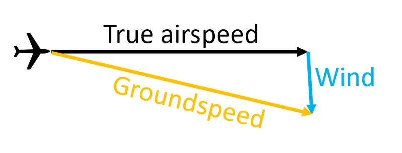
Ground Speed
In relation to a fixed location on the ground, ground speed is the rate of movement of an aircraft. Consider it this way: A plane's shadow would travel across the ground at a certain pace. An aircraft's ground speed will increase if there is a strong wind pushing it.A comparison of the ground speed to the wind speed must follow the guidelines for vector comparisons because ground speed is also a vector quantity.
Air Speed
The airspeed, or relative velocity between an object and the air, is a crucial factor in the production of lift. From a ground position, airspeed cannot be determined directly; instead, it must be calculated from the ground speed and the wind speed. The vector difference between ground speed and wind speed called the airspeed.
Airspeed = Ground Speed - Wind Speed
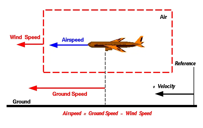
Ground speed affects how quickly an aeroplane will get at its destination; airspeed decides whether there is sufficient airflow around an aircraft to enable it to fly.
3.Why is it not recommended to move it on the airport's ground using an aircraft's engine power?
When an engine or aircraft system needs to be operational in order to be evaluated for function, ground running may be done before, during, or after the repair of a defect or scheduled maintenance on an engine or an aviation system.The risks associated with engine ground running include the possibility that those in the pilot seats on the flight deck will lose control of the aircraft. The principal undesired effects of such static running are those caused by the aircraft moving accidentally while the engine is operating, which is essentially a loss of control, especially when high power engines are used. A plane's own structure, surrounding aircraft, or airside buildings can all sustain damage. Furthermore, there is a chance that ground support staff members who are perhaps around the aircraft could be hurt.The engine's loud noise is harmful to nearby humans and other living things since it is so loud. Therefore, using engine power to move on the ground is not advised for the reasons mentioned.
Taxing is the process of moving an aeroplane on the ground while using its own engine power.
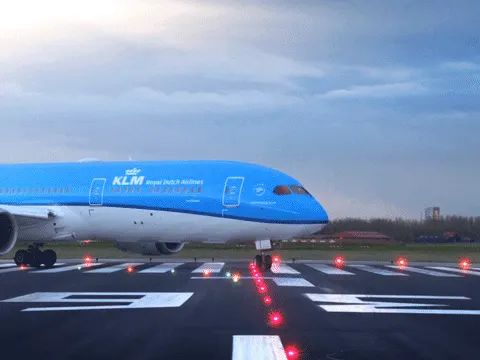
A pushback truck lifts the front of the plane; this process, known as towing, is used in most airports to move the plane from its parking spot and onto the taxiways.
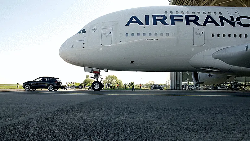
The aeroplane may sustain damage while running on high power. Compared to a pilot, a truck driver finds it simpler to see the outside and operate the vehicle. Compared to a pilot, the pushback driver is very familiar with the airport. Another significant benefit is the significant fuel savings for such a small item. These could cause damage to aircrafts nearby if it reverses on its own. significant risk of jet blast and nearby buildings.
By using Taxibot to tow, we can conserve gasoline and reduce damage to the engine. Only once the aeroplane has reached the runway will the ignition be turned on. By as much as 85%, using Taxibots will drastically reduce the amount of fuel necessary to taxi an aeroplane. Taxi boats will also aid in decongesting boarding gates and the apron area by offering effective pushbacks.
4.How is a plane pushed onto the runway when it is time to take off?
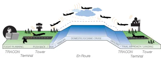
When an aeroplane is being pushed backwards away from an airport gate during an airport operation called pushback, outside force is used. Pushbacks are executed by specialised, low-profile vehicles known as pushback tractors or tugs.
Taxiways are used by aeroplanes to go between locations on an airport, such as from a hangar to the runway.The takeoff roll and landing rollout, which are the accelerating run and descending run along a runway, respectively, before takeoff and landing, respectively, are not referred to as "taxiing."
Pushback occurs when tractors or tugs are used to push an aeroplane backwards away from the airport gate. A tug for an aeroplane will pull up directly in front of the nose wheel as we get closer to takeoff. The tug may be a "wheel-lift" tug or it could be directly connected to the plane's nose gear with a tow bar. These tugs support the nose gear while lifting it up and then moving the aircraft. As a result, the tug driver has control over the plane's pushback direction.
Electric motors fitted to the aircraft's landing gear and pilot-controlled tugs are two examples of the new taxi technologies that are emerging. Both promise to reduce airport noise and conserve fuel.
The engines of aeroplanes allow them to move forward along the ground. They thus exert themselves to reach the runway.It is true that, for the most part, a small vehicle is required to push the larger commercial aircraft away from the terminal building in reverse since, even though a plane can reverse its thrust, it is not always safe to do so. The smaller vehicles thereby push the larger aircraft back from the structures, but after they have done so, the aircraft can continue to move forward by using a limited amount of engine power, as any aircraft can.
TAKE OFF
The takeoff phase of flight, which often begins on a runway, is when an aircraft changes from moving along the ground (taxiing) to flying in the air. During takeoff, the engines are typically running at maximum capacity. The aircraft comes to a stop at the runway's beginning after taxiing. The engines, especially piston engines, are routinely ramped up at high power prior to departure to check for engine-related issues. Considerable noise is produced by this. The moment the pilot lets off the brakes, the aircraft begins to accelerate quickly until the required takeoff speed is reached.
The runway is pushed toward by the aircraft.
5.Learn about the force required to brake upon landing, takeoff power, tyre design, rolling resistance, and tyre pressure.
- Take off power
Takeoff power is the amount of force that an aircraft's engines need to generate to raise it into a horizontal takeoff. This phrase is frequently referred to as takeoff thrust. In order to reduce takeoff engine wear, the pilot uses less thrust. Reduced power and controlled takeoff are commonplace. Prior to every takeoff, the performance is meticulously analysed to guarantee that the right speed, power setting, and flapes are employed for the weight of the takeoff on the runway intended and at the right temperature. When taking off utilising this technique, it is always feasible to boost the power if necessary.
Typically, full power is applied during takeoff for light aircraft. In order to extend engine life, lower maintenance costs, and lower noise emissions, large transport category aircraft may operate at reduced power during takeoff. The power used can then be raised in specific emergency situations to improve the performance of the aircraft. The engines, especially piston engines, are routinely ramped up at high power prior to departure to check for engine-related issues. The plane can accelerate up to rotational speed. The term "rotation" refers to the aircraft's pivoting while it is still on the ground around the axis of its main landing gear, typically as a result of slight adjustments to the flight controls that create or enable this change in aircraft attitude.
- Design and construction of aircraft tyres
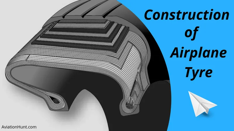
The purpose of a tyre is to support extremely large loads for brief periods of time. As more tyres are needed to spread the weight of the aircraft more equally, the weight of the aircraft causes a rise in the number of tyres needed. To aid stability in strong crosswinds, to channel water away to minimise hydroplaning, and to provide braking action, aircraft tyres are built with certain tread patterns. Additionally, there are aircraft tyres (which are attached to the interior of the wheels) that melt at a specific temperature. If maximal braking is used during a failed takeoff or an emergency, tyres frequently overheat. The fuses offer a safer failure mode that minimises tyre explosions by controlling tyre deflation, hence limiting harm to aircraft and nearby objects.
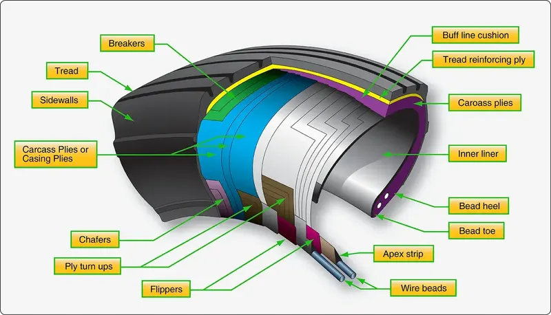
The following materials are used in tyre construction:
Tread: To achieve the appropriate level of toughness, durability, and wear resistance, the tread is comprised of rubber blended with other additives. The tread pattern is created to meet the operational needs of the aircraft, and the ribbed tread pattern is frequently employed since it provides high traction on a variety of runway surfaces.one or more layers of cloth that serve to stabilise and reinforce the tread area for use at high speeds(Tread Reinforcing Ply).
Buff Line Cushion:To improve the adhesion between the tread reinforcing ply and the breakers or casing plies, the buff line cushion is formed of rubber compound.
Sidewall: The outside casing ply is shielded by a rubber protective covering known as the sidewall. It reaches the bead area from the tread edge.
Breakers: To protect the casing plies, reinforce, and stabilise the tread region, breaking plies of rubber-coated cloth are positioned beneath the buff line cushion.
Wire Beads: Steel wire hoop structures with a high tensile strength that anchor the casing plies and offer a stable mounting surface for the wheel. The bead heel refers to the outer edge of the bead that contacts the wheel flange. Bead toe refers to the inner bead edge.
Casing Plies: Running at right angles to one another, alternate layers of rubber-coated cloth provide the tyre its strength.
Apex Strip: The top of the bead bundle is attached with a wedge of rubber.
Flippers: Layers of rubberized fabric that increase the tire's durability by helping to secure the bead wires to the casing.
Ply Turnups: The ply turnups are formed by wrapping the casing plies over the wire beads to anchor them.
Chafer: To reduce friction, place a layer of fabric or rubber between the wheel and the casing plies.
Liner: The liner in tubeless tyres serves as a built-in tube and prevents gas from leaking into the casing plies by having a low permeability rubber layer on top of it. To avoid the tube chafing against the inner ply, tube-type tyres have a thinner liner.
- Tyre Pressure
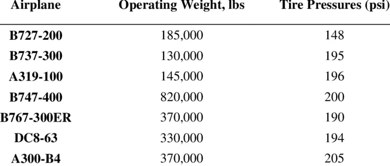
For airliners, aircraft tyres can function at pressures of up to 200 psi (14 bar; 1,400 kPa), and even higher for business jets. The 12 Boeing main tyres each weigh 120 kg (260 lb), have a diameter of 134 cm, and are inflated to a pressure of 220 psi (15 bar; 1,500 kPa) (53 in).
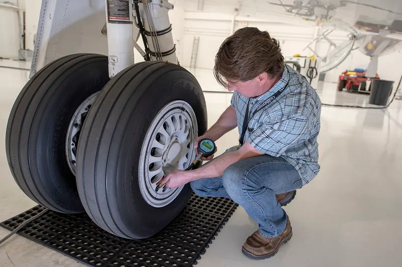
A tyre or tyre for an aircraft is made to bear exceptionally large loads for a brief period of time. As more tyres are needed to spread the weight of the aircraft more equally, the weight of the aircraft causes a rise in the number of tyres needed. To aid stability in strong crosswinds, to channel water away to minimise hydroplaning, and to provide braking action, aircraft tyres are built with certain tread patterns. Fusible plugs that are intended to melt at a specific temperature are also seen in aircraft tyres. If maximal braking is used during an emergency landing or aborted takeoff, tyres frequently overheat. The fuses offer a safer failure mode that minimises tyre explosions by controlling tyre deflation, hence limiting harm to aircraft and nearby objects.
- Brake upon landing
In order to minimise stopping distance, reduce pilot workload, and achieve smooth braking action, aircraft are equipped with an autobrake system that regulates the deceleration of the aircraft by automatically optimising the application of brake force independent of pilot operation of the brake pedals. A skid control feature is another typical component of aeroplane braking systems. Skid control systems prevent wheel lockup similarly to anti-lock brakes on a car. They reduce stopping distance and counteract tyre damage from skidding, such as accelerated tyre wear and blowouts. By using an ideal braking force that maximises the coefficient of friction and stays just below the force that would cause sliding, skid control is achieved.
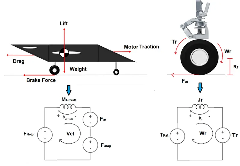
One approach compares the continuously detected wheel speed to an estimated aeroplane velocity to determine the appropriate force. Wheel slip is represented by the difference between the two numbers, and braking force is reduced if it exceeds a certain level.
To safely land on runways, aeroplanes depend on braking systems. Most commercial aircraft travel at cruising altitude at a speed of around 500 to 600 mph. But they have to slow down when they arrive. For instance, the normal landing speed of a 747 is between 160 and 170 mph. Aircraft must also swiftly brake after touching the runway in order to stop completely.
Wing spoilers : Wing spoilers are frequently used by aircraft to help in braking during landing. Spoilers are extensible flaps on the extremities of an airplane's wings, not to be confused with ailerons. As the aircraft approaches the runway, the pilots can raise the spoilers to slow it down. Pilots frequently leave the wing spoilers high even while on the runway. Raised wing spoilers generate drag, which in turn causes the aeroplane to slow down so that it can brake more rapidly.
Disc Brakes:In addition to wing spoilers, airplanes use disc brakes. Airplane disc brakes are similar to the braking system in automobiles. They consist of a pair of calipers that, when engaged, squeeze pads against the rotors of an airplane’s landing gear. Disc brakes are designed to remain static at all times. In other words, they don’t rotate with the wheels of an airplane’s landing gear. As the wheels turn, the disc brakes will remain static and stationary. They are a vital component of an airplane’s braking system because they are designed to apply pressure to the airplane’s wheels. Disc brakes will squeeze the wheels, thereby slowing down the speed at which they spin. In turn, this reduces the speed of the airplane .
Reverse thrust : Finally, many jet airplanes use reverse thrust to assist with braking during landings. Reverse thrust is a feature in jet engine airplanes that, as the name suggests, involves the reversal of the engines’ thrust. When flying, the thrust is projected out the rear of an airplane’s engines. When landing, however, pilots may use the reverse thrust feature. Reverse thrust changes the direction of the engines’ thrust. Rather than projecting out the rear, the thrust will be projected out the front. This reversal of thrust provides deceleration that allows airplanes to slow down more quickly when landing.
- Tyre design, rolling resistance
The tyre body at the ground interface will be deflected when a loaded wheel and tyre is forced to roll in a certain direction because of the combination of the vertical load and the forward rolling action on the tyre body. While the forward rolling motion of the wheel will compress and spread the leading contact edge and wall in the region of the tread, the vertical load tends to flatten the circular profile of the tyre at ground level. As it gradually breaks free from the ground response, the trailing edge will also tend to lower its contact pressure and expand.Consequences of the constant deformation and recovery of the tyre body at ground level include the energy consumed to roll the tyre over the ground and the fact that some of that energy is not entirely recovered as strain energy when the tyre assumes its original shape. Unfortunately, while the body is under stress, the strain that is created is a direct result of the stress. Because the tyre material is not totally elastic, the strain does not immediately follow the release of the tension. As a result, the strain for a given degree of stress is greater when the stress is falling than when it is growing. As a result, even when all the stress has been removed, there is still some strain. The main reason for the rolling resistance of the tyre is a phenomenon known as hysteresis.
It is defined as the resistance to motion experienced when a body rolls on an object . When an aeroplane takes off from the runway and lands on the runway, rolling resistance is seen in the aircraft.
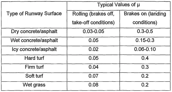
rolling resistance force can be written as: Frr=Urr*m*g(N)
Where Urr= coefficient of rolling resistant
m= Mass(kg)
Frr= rolling resistance (N)
g= acceleration due to gravity(9.81m/s^2)
Below are some examples of rolling resistance coefficient values for various runway surfaces.
PART B
6.A)With necessary assumptions, calculate the force and power required to push / pull an aircraft by a towing vehicle.
Let us assume;
Mass of aircraft M1 = 280,000kg
Mass of Towing vehicle M2 = 55,000kg
Coeffiecient of rolling resistance for dry concrete road, µrr = 0.03
Frontal area of aircraft, A = 250m^2
Drag coefficient of an aircraft, Cd = 0.6
Drag coefficient of a towing vehicle, Cd = 0.15
Density of air =1.225kg/m^3
G = 9.81
Speed of an aircraft V =20 * (5/18) = 5.556 m/sec
Rolling Resistance force
For Aircraft-
`Frr=murrxxmxxg`
`Frr=0.03xx280000xx9.81`
=82404 N
For Towing Vehicle-
`Frr=0.03xx55000xx9.81`
=16186.5 N
The rolling resistance of both the towing vehicle and the aircraft must be added.
Frr= Frr(aircraft)+Frr(vehicle)
= 82404+16186.5
=98590.5 N
Aerodynamic drag force
Fad=`(0.5)xxrhoxxV^2xx(Cd(aircraft)+Cd(vehicle))`
=0.5*1.225*250*(5.556)^2*(0.6+0.15)
=3544.078 N
Total force of the towing vehicle
`F=Fad+Frr(aircraft)+Frr(vehicle)`
=3544.078+98590.5
=102134.578 N
Power required
P=F*V
=102134.578*5.556
= 567.46KW
The force and power of the towing vehicle carrying the aircraft are 102.134 KN and 567.46 KW.
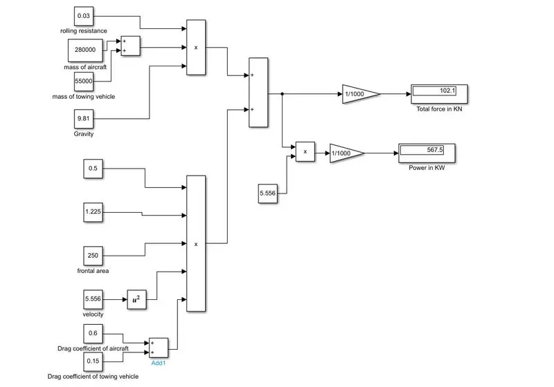
6.B)Create the force and power calculation model in Simulink.
7.A. Design an electric powertrain with type of motor, it’s power rating, and energy requirement to fulfill aircraft towing application in Simulink. Estimate the duty cycle range to control the aircraft speed from zero to highest. Make all required assumptions. Prepare a table of assumed parameters. Draw a block diagram of powertrain.
Based on previou question,
Force required to push/pull the aircraft = 102.134KN
Power required is = 567.46KW
Rated power = 950KW
Let us assume the radius of the tyre as = 25 inches (0.65 metere)
And gear ratio=8
Transmission efficiency(et)=87%
Motor efficiency (em)=95%
Then,
Torque required for the wheel (Tw) = Total force * Radius in meter
= 102.134 * 0.653
= 66.69
Motor torque = wheel torque/ (Gear ratio * et)
= 66.69/(8*0.87)
= 9.6 KNm
The required motor torque = 9.6/0.95
= 10.10 KNm
The total power required by the motor considering all efficiencies
= 567.46/(0.87*0.95)
686.025 KW
Let us assume the towing operation is done for 15 minutes(0.25 hrs)
Total energy consumed = 686.025*0.25
= 171.50 KWh
Duty cycle = Required power/rated power
= 686.025/950
= 0.722
= 72.2%
Block diagram of power train
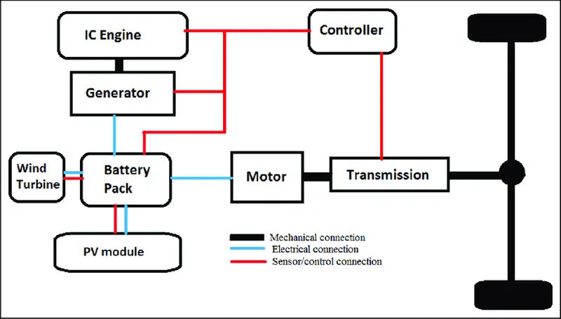
Electric motor (EM) systems press the vehicle. Electricity is supplied to the motor using a lithium ion (Li-ion) battery pack and an engine generator set (EGS). Both thermal and electrical energy can be used to power the motor. The battery stores charges from the PV panel and wind turbine, and the generator converts the engine's heat energy into electrical energy before delivering both to the motor.
Power train model designed in simulink
The simple powertrain model for an aeroplane on a runway is shown in the model below. The battery (source), motor, motor controller, and other components make up the power train in general.
This variant includes a battery and a dc drive for the four quadrant chopper (DC) The DC drive's fundamental function is that it includes the controller as well.
The powertrain for the aircraft on the runway is based on the dc 7 model.
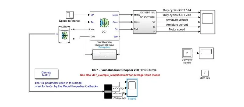
DC7 block was used. A four-quadrant DC-supplied chopper drive for DC motors, often known as a DC-DC PWM converter, is represented by the Four-Quadrant Chopper DC Drive (DC7)block. With four-quadrant operation, closed-loop speed control is a feature of this drive. The reference armature current of the machine is output by the speed control loop. The chopper duty cycle necessary to generate the requested armature current is calculated using a PI current controller. The necessary PWM signals for the chopper are then generated by comparing this duty cycle to a sawtooth carrier signal.
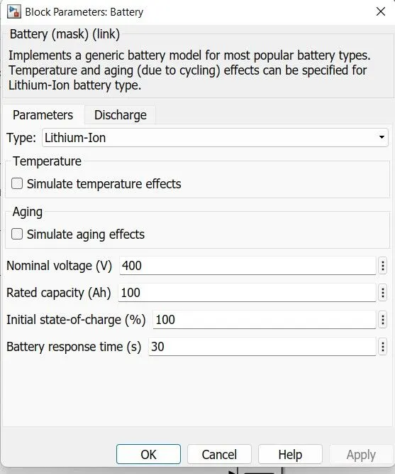
A generic dynamic model that represents the most common types of rechargeable batteries is implemented by the Battery block.
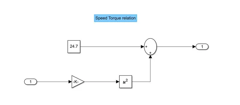
Subsystem for Vehicle Load Characteristics:
TTR= 24.7+0.0051⋅ω2
We used the vehicle characteristics equation to relate the vehicle's torque and speed.
A subsystem model has replaced the linear load torque block in accordance with the load characteristics provided by
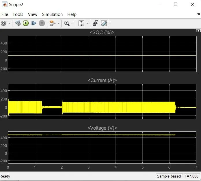
Battery details:
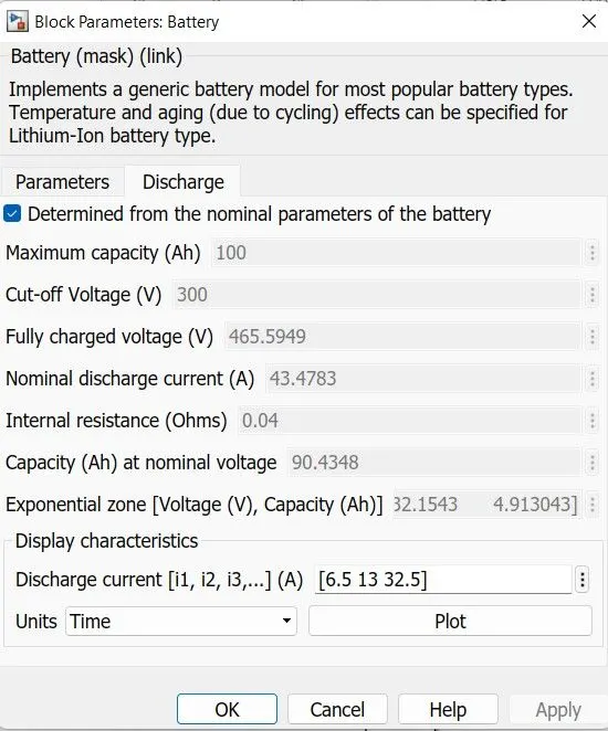
on discharge:
First graph is battery state of charge graph. Second graph is battery input current and third graph is battery voltage.
Scope analysis according to given parameters:
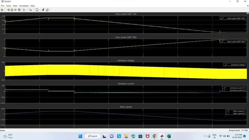
The first slot is for the duty cycle of IGBTs 1 and 2, while the second slot is for IGBTs 2 and 3. The third and fourth graphs show the armature voltage and current, respectively. The graphs of armature current and motor speed are comparable. A motor's armature current determines its speed.
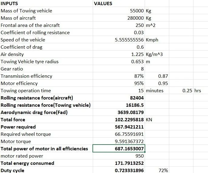
7.B-Excel sheet copy for determining the force and power of an aircraft's powertrain:
Conclusion
- There has been a weight search and list of many aircraft kinds.Explained is the difference between ground speed and air speed.It has been made clear that moving it on the airport's ground using an aircraft's engine is not advised. When an aircraft is prepared for takeoff, it is pushed to the runway. Study takeoff power, tyre design, rolling resistance, tyre pressure, and brake forces after landing.
- Simulink was used to design an electric powertrain that included the type of motor, its power rating, and the energy needed to complete the aeroplane towing application. calculated the duty cycle range to regulate the aeroplane speed from the lowest to the greatest. a powertrain block diagram was created. Additionally, the settings in the excel sheet are designed one at a time.
Reffernces