Project-1: Powertrain for aircraft in runways
PROJECT 1:
POWERTRAIN FOR AIRCRAFT IN RUNWAYS
PART A
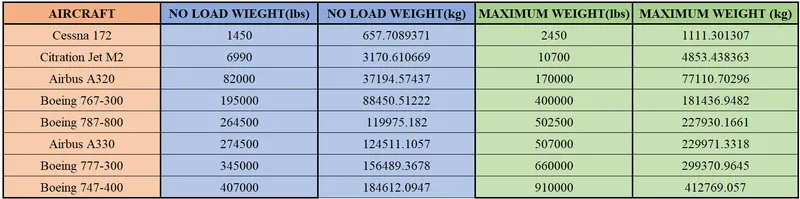
1:WIEGHTS OF DIFFERENT TYPES OF AIRCRAFTS
2:DIFFERENCE BETWEEN GROUND SPEED AND AIR SPEED
- Ground speed- The speed at which aircraft moving relative to ground
- Air speed - The speed at which aircraft moving relative to ground
- If the aircraft flying in the direction of wind,it experiences tailwind and ground speed is higher than airspeed
- If the aircraft flying against the wind,it experiences headwind and ground speed is less than airspeed
- The relationship between ground and air speed can be written as
Ground speed = Air speed + Wind speed
3:WHY AIRCRAFT ENGINE POWER NOT USED TO MOVE ON THE RUNWAY
- The aircraft engine consumes large amount of fuel to move them
- The fuel used in aircraft are jet fuel and AVGAS ,which are very expensive
- Also considering the large amount of carbon emissions and noise pollutions
- Aircraft engine is not recommended to move it in the runway
4:HOW AIRCRAFT MOVED TO RUNWAY
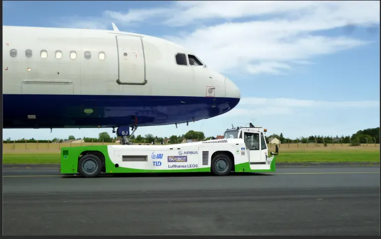
- The aircraft moved in the runway using towing vehicle
- The towing vehicle canmove a aircraft forward and backwardby attaching them to towing vehicle
- The following image shows the towing vehicle moving an aircraft
5:LEARN ABOUT AIRCRAFT PARAMETERS
a)TAKE OFF POWER:
- The power required to lift the aircraft from the ground is called take off power
- The engine full power may used to take off lighter aircraft
- But the large aircraft only use less power to take off in order to improve engine life ,reduce maintanenece and reduce noise
- The forces acting on an aircraft while take off are Air drag ,rolling resistance and the propulsion power
- The force required to take off the aircraft can be written as
Ftake-off = Fthrust - Frr - Fad
- Where Fthrust-propulsion force of turbine
- Frr- rolling reistance force
- Fad - Aerodynamic drag force
- The take off power can be calculated as
Ptake-off = Ftake-off * V
- Where V-velocity of the aircraft
b)TYRE DESIGN:
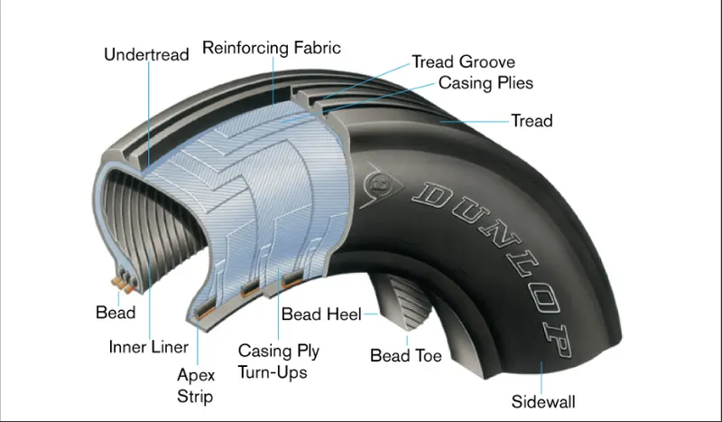
- An aircraft tyre designed to withstand extremely heavy loads for shorter duration
- The number of tires required for aircraft increases with the weight of the aircraft
- Aircraft tire tread patterns are designed to facilitate stability in high crosswind conditions and braking effect
- Aircraft tires are usually inflated with nitrogen to minimize expansion and contraction from extreme changes in ambient temperature and pressure experienced during flight
- The below image shows the design of tyre used in aircraft
c)ROLLING RESISTANCE:
- The force acting between the tyre and the track or runway is called rolling resistance
- The rolling resistance may vary according to the tire presure and runway conditions (climate)
- The rolling resistance can be calculated as
Frr = urr*m*g
- Where,Frr-rolling resistance force
- urr - coefficient of rolling resistance
- m-mass of the vehicle
- g-acceleration due to gravity
d)TYRE PRESSURE:
- Aircraft tires generally operate at high pressures, up to 200 psi (1,400 kPa)
- The main landing gear on the Concorde was typically inflated to 232 psi (16.0 bar)
- Its tail bumper gear tires were as high as 294 psi (20.3 bar).
- The aircraft tyres should properly inflated to prevent it from any severe damage or explosion
- Research says that five percent of tire pressure losses per day under typical operations
- At this rate of loss ,the tire needs frequent servicing
e)BRAKE FORCES:
- Aircraft brakes stop a moving aircraft by converting its kinetic energy to heat energy by means of friction between rotating and stationary discs located in brake assemblies in the wheels.
- An electrical signal is sent from the flight deck to hydraulic actuators near the main landing gear to apply brake
- Hydraulic fluid at 3,000 pound per square inch is used to force the brake unit against the wheel,to slow it down
- Nowadays electric brakes also implemented on aircraft,which reduces the cost and maintanence
- The braking force can be calculated as
Fbrake = 0.5* (m*V^2)/d
- Where m - mass of the aircraft
- V-velocity of the aircraft
- d-stoppping distance
PART B:
6A:CALCULATE FORCE AND POWER REQUIRED TO MOVE AN AIRCRAFT BY A TOWING VEHICLE
PARAMETERS:
- Mass of the towing vehicle Mt=1500 kg
- Mass of the aircraft Ma=184612.1kg
- Rolling reistance coefficient urr = 0.02
- Air density p= 0.015
- Width of the vehicle W=2.5 m
- Height of the vehicle H=2 m
- Drag coefficient Cd=0.8
- Velocity of the vehicele =5.0kmph
- Acceleration time = 12 s
EQUATIONS:
- The rolling resistance force Frr can be calculated
Frr= urr*m*g
- Where,urr - coefficient of rolling resistance
- m-mass of the vehicle
- g-acceleration due to gravity
- The Aerodynamic Drag force Fad can be calculated as
Fad=0.5*p*A*Cd*v^2
- Where,p-Air density in kg/m3
- A-Frontal Area (A=W*H ,W&H width and height of vehicle)
- Cd-Drag coefficient
- v-Velocity in m/s (speed in kmph convert to m/s by dividing it by 3.6)
- The acceleration force can be calculated as
Fac = m*a
- Where ,m-mass of thevehiclein kg
- a-acceleration in m/s2
- The total traction force can be calculated as
Fte = Frr+Fad+Fac
- The total traction power (Pte)can be calculated as
Pte= Fte *v
- Where,Fte-total traction force
- v-velcoity of vehicle in m/s
SOLUTION:
- The total mass m can be calculated
- m = Mt+Ma
- m=1500+184612.1
- m=186112.1kg
- The rolling resistance force can be calculated as
- Frr= urr*m*g
- Substituting all known values in the equation
- Frr = 0.02*186112.1*9.8
- Frr=36477.9716 N
- The Aerodynamic Drag force Fad can be calculated as
- Fad=0.5*p*A*Cd*v^2
- The frontal area can be calculated as
- A=W*H
- A=2.5*2
- A=5 m^2
- The velocity in kmph converted to m/s as
- v=5/3.6 m/s
- Substituting all known values
- Fad = 0.5*0.015*5*0.8*(5/3.6)^2
- Fad = 0.03*1.92901235
- Fad= 0.05787037 N
- The acceleration force can be calculated as
- Fac = m*a
- The acceleration can be calculated as
- a=v/t
- a=(5/3.6)/12
- a=0.1157 m/s^2
- Substituting alll known values
- Fac = 186112.1*0.1157
- Fac = 21540.74 N
- The total traction force can be calculated as
- Fte = Frr+Fad+Fac
- Substituting all known values
- Fte = 36477.9716 +0.05787037 +21540.74
- Fte = 58018.7695 N
- The total traction power (Pte)can be calculated as
- Pte= Fte *v
- Substituting all known values
- Pte = 58018.7695 *(5/3.6)
- Pte = 80581.62 w
- Converting to kw by dividing 1000
- Pte = 80.581 kw
CONCLUSION:
- The force and power required by a towing vehicle to move a Boeing 747-400 of 184612.1kg are 58018.8 N and 80.5kw respectively
6B:DEVELOP A SIMULINK MODEL FOR CALCULATED FORCE AND POWER
SIMULINK MODEL:
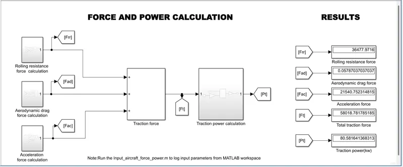
- The simulink model for calculation of force and power is shown below
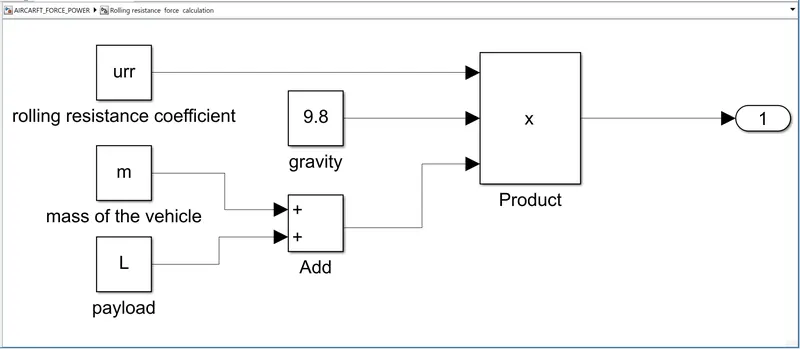
- The rolling resistance force calculation
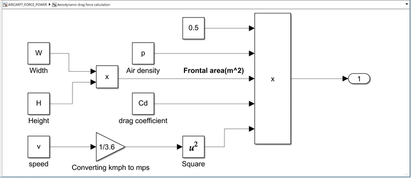
- The aerodynamic drag force calculation
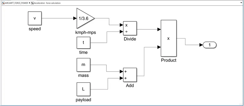
- The acceleratio force calculation
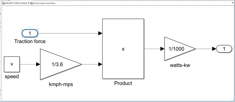
- The traction power calculation
REPORT:
- The input parameters used in the model logged into MATLAB workpace
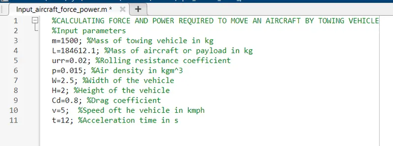
- The rolling resistance calculation
- Frr=urr*m*g
- urr-coefficient of rolling resistance defined by a constant block
- m-total mass which is addition of mass and payload of the vehicle
- g-acceleration due to gravity constant 9.8m/s2
- These values multiplied by a product block to obtain Frr-rolling resistance force
- Created a subsystem of these blocks
- The output connected to a display block through goto and from blocks
- The Aerodynamic Drag force Fad can be calculated as
- Fad=0.5*p*A*Cd*v^2
- Where,p-Air density defined by a constant block
- A-Frontal Area obtained by multiplying width and height using a product block
- Cd-Drag coefficient is a constant block
- v-Velocity in kmph converted to m/s by multiplying a gain block of value 1/3.6
- The velocity in m/s squared using a square block
- These values multiplied by a product block to obtain air drag force Fad
- Created a subsystem of these blocks
- The output connected to a display block through goto and from blocks
- The acceleration force can be calculated as
- Fac = m*a
- m-mass obtained by adding mass of vehicle and payload by add block
- a-acceleration obtained by dividing velocity in m/s by time using a divide block
- Created a subsystem of these blocks
- The output connected to a display block through goto and from blocks
- The total traction force can be calculated as
- Fte = Frr+Fad+Fac
- Adding outputs from the subsystems using a add block
- The total traction power (Pte)can be calculated a
- Pte= Fte *v
- The total traction force multiplied by velocity in m/s by product block to obatin the traction power
- The output multiplied by a gain block of value 1/1000 to convert watts to kilo watts
- Created a subsystem out of it
- The output displayed through goto and from block in display block
- Run the model
- Outputs displayed in the display blocks
RESULTS:
- The results of the above simulink model is shown below
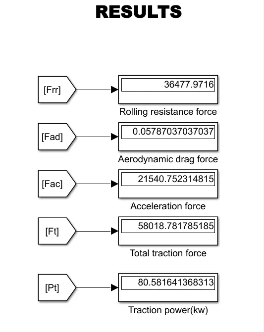
CONCLUSION:
- Developed the simulink model for the calculation of force and power
- The outputs displayed and verified
7A:ELECTRIC POWERTRAIN OF AIRCRAFT TOWING APLLICATION
POWER AND ENERGY CALCULATION:
- The power obtained for the aircraft towing vehicle application is 80.6kw
- Assuming towing vehicle travelled for 15 mins
- The energy can be calculated as
- E = P*t in kwh
- Where P-power required by the vehicle
- t-time in hours
- Substituting all known values in the energy equation
- E=80.6*0.25
- E = 20.15kwh
- The towing vehcle energy consumption will be 20kwh for15mins
- Assuming the motor parameters
- Motor input voltage =600v
- Motor input current =150A
- The input power can be calculated as
- Pin = V*I
- Pin = 600*150
- Pin = 90000w or 90kw
- The motor torque assumed to be 2000 Nm for pulling aircraft using towing vehicle
DUTY CYCLE:
- The duty cycle of the motor converter to achieve the required power can be calculated as
- Duty cycle = output power/input power
- Duty cycle = 80600/90000
- Duty cycle = 0.89 or 89%
SIMULINK MODEL:
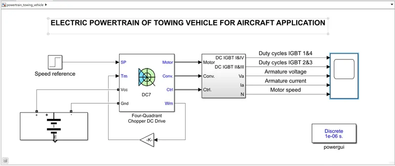
- The electric powertrain model of towing vehicleforaircraft applicationis shown below
REPORT:
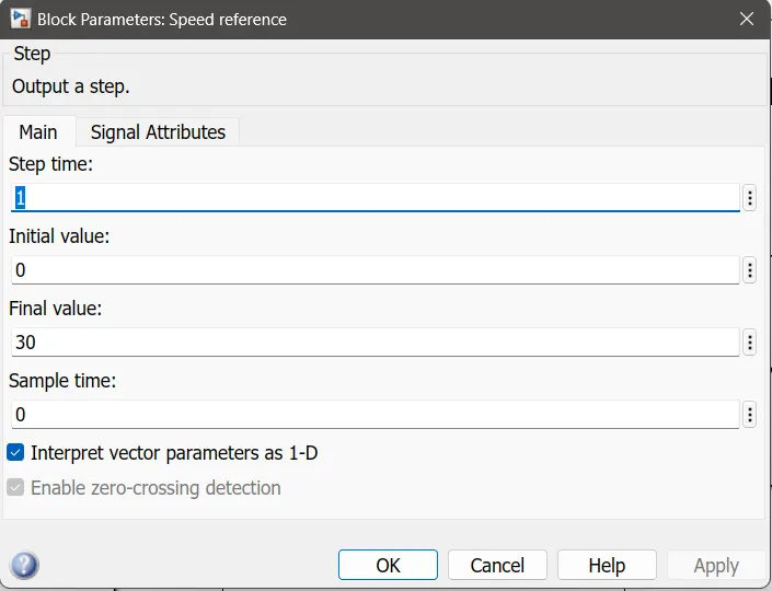
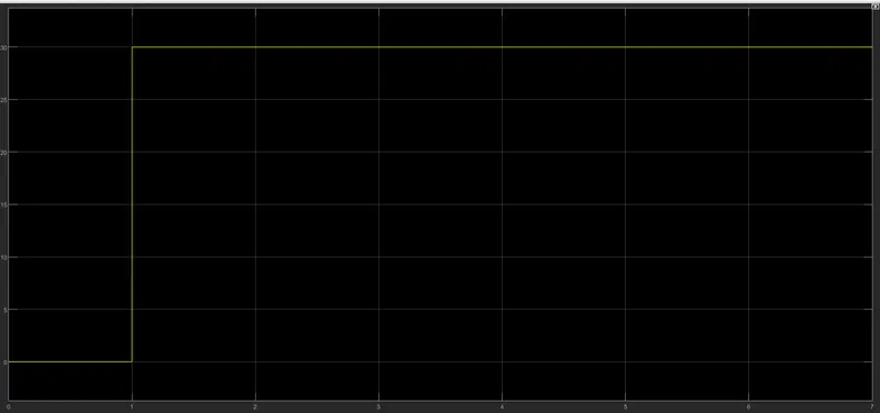
- The speed reference to the DC7 converter provided by a step block
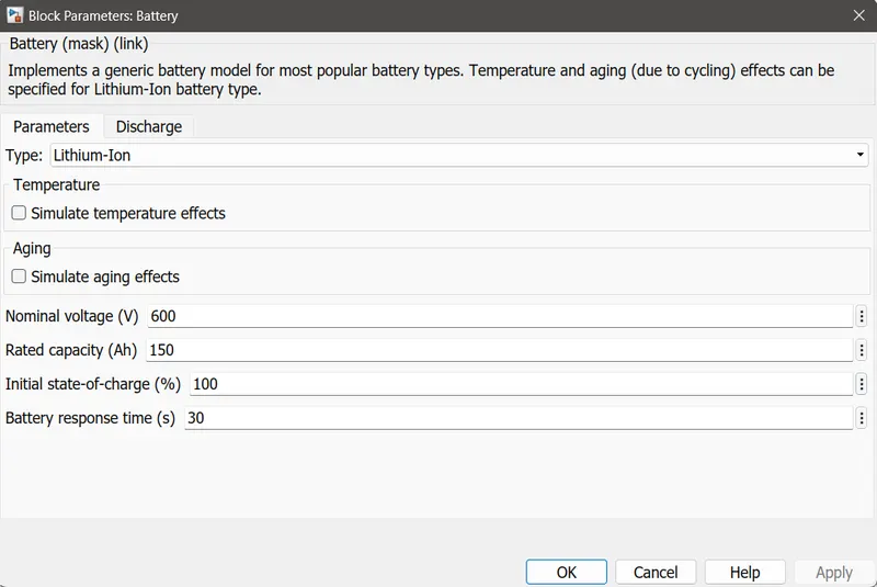
- The battery mask block used to provide the input supply to the DC7 converter
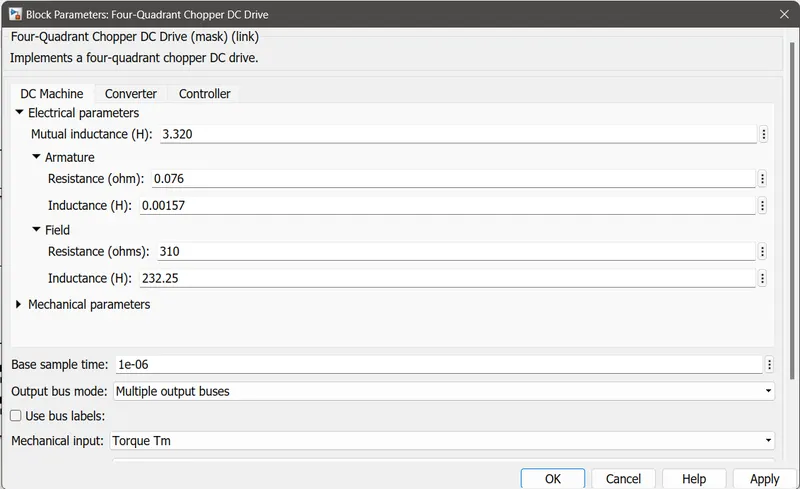
- The DC7 converter block parameters set as shown below
- The torque input for the DC7 power converter is provided by a feedback from the motor speed
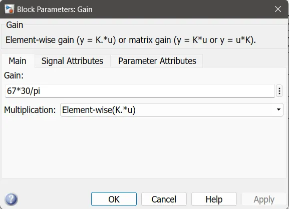
- The gain value set to achieve the assumed motor torque of 2000Nm
- The output parameters from the DC7 block are motor ,controller and converter output
- The output parameters connected to a bus selector as shown below
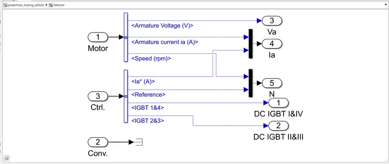
- The output 1 &2 are the duty cycles of IGBT in the converters
- The output 3 is the armature volatge of the motor
- The output 4 is the armature current of the motor
- The output 5 represents the actaual speed and the reference speed
- The outputs are connected to the scope block
- The power gui block added and changed simulation type to discrete
- The DC7 converter will act as four quadrant chopper circuit
- The switching operation of IGBT done in a way to achieve the required motor speed and torque
RESULT:
- The reference speed inputgiven to the DC7 converter is shown below
- The final results of DC7 converter and motor are shown below
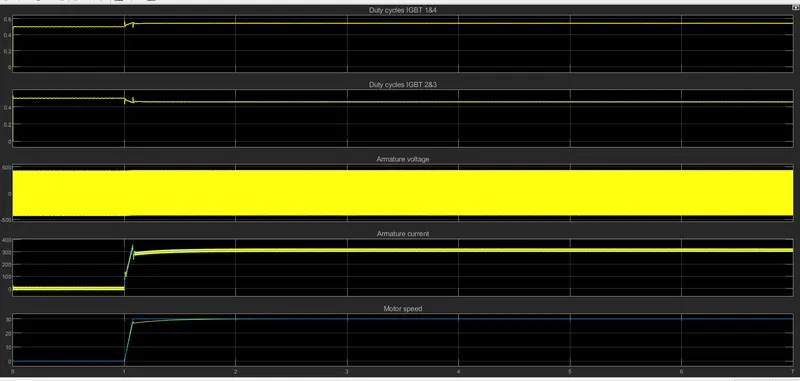
- Graph 1:The duty cycles of IGBT 1&4
- Graph 2:The duty cycles of IGBT 2&3
- Graph 3:The armature voltage of the motor
- Graph 4:The armature current of the motor
- Graph 5:The actual speed and the reference speed
- By analying the graph ,the actual speed of the motor is equal to reference speed input
BLOCK DIAGRAM:
- The block diagram of the electric powertrain is shown below
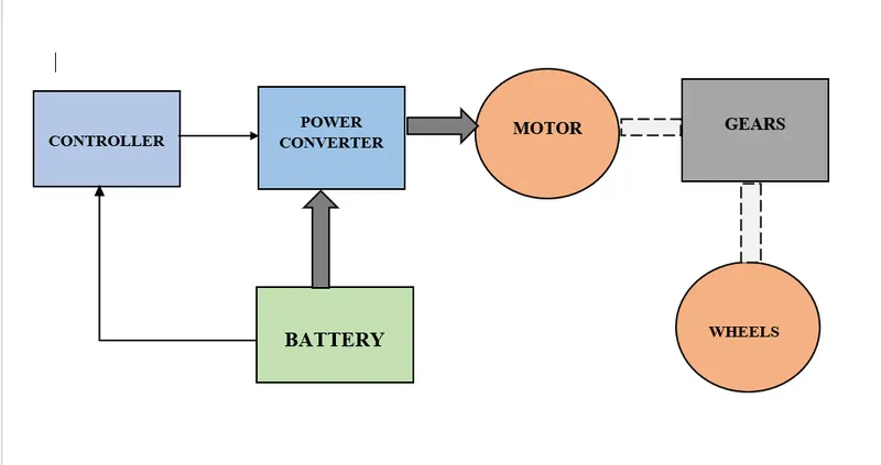
- BATTERY -DC source or input voltage to power converter ,controller input voltage also provided by the battery
- CONTROLLER-It provides contol signals or gate signal to the power converter ,controlling the duty cycle with repect to the reference value
- POWER CONVERTER- Four-quadrant chopper circuit ,which act as speed controller of motor
- MOTOR-DC motor or inductio motors
- GEAR-Motor connected to the axles through a gear system
- WHEELS-Axles connected to the wheels ,which moves the vehicle body
CONCLUSION :
- The simulink model of electric powertrain of towing vehicle application is designed
- The duty cycle and energy requirements of the motor calculated
- Block diagram of electric powertrain is designed
7B:DESIGN THE PARAMETERS IN EXCEL SHEET:
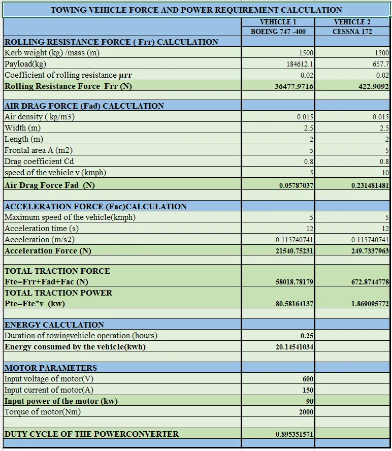
- The excel calculation for the force and power requirement of aircraft towing vehicle application is shown below
CONCLUSION:
- Designed the parameters in the excel sheet and the outputs verified