Project-1: Powertrain for aircraft in runways
Part A:
Study#1:
Total weight of various types of aircrafts is listed below and it ranges from 1.1 Ton to 640 Tons of weight.
| Aircraft | Empty Weight | Max Fuel Weight | Max Cargo Weight | Max Gross Takeoff Weight |
| Antanov AN-225 | 628,000 lbs | 661,400 lbs | 417,000 lbs | 1,411,000 lbs |
| 285,000 kg | 300,000 kg | 190,000 kg | 640,000 kg | |
| Airbus A380-800 | 611,000 lbs | 560,000 lbs | 185,000 lbs | 1,268,000 lbs |
| 277,000 kg | 254,000 kg | 84,000 kg | 575,000 kg | |
| Boeing 747-800 | 485,300 lbs | 427,400 lbs | 295,000 lbs | 987,000 lbs |
| 220,100 kg | 194,000 kg | 134,000 kg | 447,700 kg | |
| Airbus A340-500 | 370,000 lbs | 386,300 lbs | 119,000 lbs | 820,000 lbs |
| 168,000 kg | 175,000 kg | 54,000 kg | 372,000 kg | |
| Boeing 777-300ER | 370,000 lbs | 320,800 lbs | 148,000 lbs | 776,000 lbs |
| 168,000 kg | 145,500 kg | 67,100 kg | 352,000 kg | |
| Boeing 787-10 | 299,000 lbs | 223,500 lbs | 126,300 lbs | 560,000 lbs |
| 135,500 kg | 101,500 kg | 57,300 kg | 254,000 kg | |
| Boeing 737-900 | 98,500 lbs | 53,100 lbs | 44,600 lbs | 187,000 lbs |
| 44,700 kg | 24,000 kg | 20,200 kg | 85,000 kg | |
| Airbus A320-100 | 93,900 lbs | 48,700 lbs | 44,000 lbs | 150,000 lbs |
| 42,600 kg | 22,100 kg | 20,000 kg | 68,000 kg | |
| Embraer 190 | 63,500 lbs | 28,600 lbs | 28,800 lbs | 106,000 lbs |
| 28,800 kg | 13,000 kg | 13,100 kg | 48,000 kg | |
| Gulfstream G650 | 54,000 lbs | 48,200 lbs | 6,500 lbs | 100,000 lbs |
| 24,500 kg | 21,900 kg | 3,000 kg | 45,200 kg | |
| Bombardier CRJ900 | 48,160 lbs | 19,600 lbs | 6,075 lbs | 80,500 lbs |
| 21,850 kg | 8,900 kg | 2,760 kg | 36,500 kg | |
| Bombardier Q400 | 39,300 lbs | 11,700 lbs | 18,700 lbs | 62,000 lbs |
| 17,800 kg | 5,300 kg | 8,500 kg | 28,000 kg | |
| Learjet 75 | 13,900 lbs | 6,060 lbs | 2,900 lbs | 21,500 lbs |
| 6,300 kg | 2,750 kg | 1,300 kg | 9,700 kg | |
| Cessna Citation CJ4 | 10,300 lbs | 5,800 lbs | 2,200 lbs | 17,200 lbs |
| 4,700 kg | 2,650 kg | 1,000 kg | 7,800 kg | |
| Beechcraft King Air B100 | 7,100 lbs | 3,200 lbs | 4,150 lbs | 12,000 lbs |
| 3,200 kg | 1,450 kg | 1,900 kg | 5,400 kg | |
| Diamond DA50 RG | 3,200 lbs | 340 lbs | 1,250 lbs | 4,400 lbs |
| 1,450 kg | 155 lbs | 560 kg | 2,000 kg | |
| Beechcraft Bonanza G36 | 2,500 lbs | 450 lbs | 850 lbs | 3,660 lbs |
| 1,150 kg | 200 kg | 385 kg | 1,660 kg | |
| Cessna 206H | 2,200 lbs | 520 lbs | 1,150 lbs | 3,600 lbs |
| 990 kg | 235 kg | 520 kg | 1,630 kg | |
| Sirrus SR22 | 2,250 lbs | 485 lbs | 950 lbs | 3,600 lbs |
| 1,000 kg | 220 kg | 430 kg | 1,630 kg | |
| Cessna 172R | 1,700 lbs | 380 lbs | 560 lbs | 2,425 lbs |
| 770 kg | 170 kg | 255 kg | 1,100 kg |
Study#2:
Difference between ground speed and air speed:
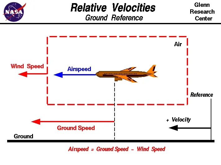
Wind Speed:
For a reference point picked on the ground, the air moves relative to the reference point at the wind speed. Notice that the wind speed is a vector quantity and has both a magnitude and a direction. Direction is important. A 20 mph wind from the west is different from a 20 mph wind from the east. The wind has components in all three primary directions (north-south, east-west, and up-down). In this figure, we are considering only velocities along the aircraft's flight path. A positive velocity is defined to be in the direction of the aircraft's motion. We are neglecting cross winds, which occur perpendicular to the flight path but parallel to the ground, and updrafts and downdrafts, which occur perpendicular to the ground.
Ground Speed:
For a reference point picked on the ground, the aircraft moves relative to the reference point at the ground speed. Ground speed is also a vector quantity so a comparison of the ground speed to the wind speed must be done according to rules for vector comparisons.
Airspeed:
The important quantity in the generation of lift is the relative velocity between the object and the air, which is called the airspeed. Airspeed cannot be directly measured from a ground position, but must be computed from the ground speed and the wind speed. Airspeed is the vector difference between the ground speed and the wind speed.
Airspeed = Ground Speed - Wind Speed
On a perfectly still day, the airspeed is equal to the ground speed. But if the wind is blowing in the same direction that the aircraft is moving, the airspeed will be less than the ground speed.
Study#3:
Commercial airplanes are equipped with engines rated from 18,000 to nearly 100,000 lb of thrust. Such thrust levels provide for safe takeoff, flight, and landing over a wide range of temperatures, altitudes, gross weights, and payload conditions. However, the exhaust wake from these engines can pose hazards in commercial airport environments. Operators and airport authorities must carefully consider these hazards and the resulting potential for injury to people and damage to or caused by baggage carts, service vehicles, airport infrastructure, and other airplanes. so, it is not recommended to use aircraft engine power to move it on the ground at Airport due to the following reasons:
- Effectively a loss of control can happen, especially during high power engine running. Damage can occur to the aircraft itself or other or to airside structures.
- There is a risk of injury to ground support personnel who may be in relatively close proximity to the aircraft due to the powerfull thrust from engine.
- The plane engines are very loud. When more than one plane will add up their sound, than it will create to noise pollution to the airport environment.
- High Fuel consumption.
- Wear and tear of the engine.
Study#4:
Towing is forward movement of aircraft with the help of a Towing tractor with aircraft engines not running.
Pushback is reverse movement of aircraft with the help of a towing tractor generally away from the terminal building
Taxing is the movement of an aircraft on the ground, under its own power. The aircraft always moves following the yellow lines, to avoid collision with the surrounding buildings, vehicle or other aircrafts. The taxiing motion has a speed limit. Before making turn the pilot reduces speed further to prevent tire skids just like other vehicles. The reason for taxing is to reach the vehicle into runway or from runway to terminal.
Following the taxiway aircraft reaches the runway. Takeoff is the phase of flight in which an aircraft goes through a transition from moving along the ground (taxiing) to flying in the air, usually starting on a runway. Usually the engines are run at full power during takeoff. Following the taxi motion, the aircraft stops at the starting line of the runway. Before takeoff, the engines, particularly piston engines, are routinely run up at high power to check for engine-related problems. This makes a considerable noise. When the pilot releases the brakes, the aircraft starts accelerating rapidly until the necessary speed for take-off is achieved.
Study#5:
Take Off Performance:
Take off performance can be predicted using a simple measure of the acceleration of the aircraft along the runway based on force equilibrium.
The forces involved will be,
T – Thrust of propulsion system pushing aircraft along runway.
D – Aerodynamic Drag of vehicle resisting the aircraft motion.
F – Rolling resistance friction due to the contact of wheels or skids on the ground.
During take-off run the imbalance in these forces will produce an acceleration along the runway.
dv/dt=(T-D-F)/m
Where, dv/dt is the acceleration along the runway and m is the mass of the vehicle.
Tyre Design:
Design and Construction of Aircraft tyre
Carcass plies are used to form the tire. They are sometimes called casing plies. An aircraft tyre is constructed for the purpose it serves.
- They support the weight of an aircraft while it is on the ground.
- It also provides the necessary traction for braking and stopping of an aeroplane.
- Tyre also helps to absorb the shock of landing and provide cushioning the roughness of takeoff, roll-out, and taxi operations.
Unlike an automobile or truck tyre, it does not have to carry a load for a long period of continuous operation. However, an aircraft tyre absorbs the high impact loads of landing, and also it’s operating at high speeds for a short time when required.
Retreading – Retreading is methods of restoring a worn tyre by renewing the tread area or by renewing the tread area plus one or both sidewalls. Repairs are included in the tyre retreading process.
Load Rating – Load rating is the maximum permissible load at a specified inflation pressure.
Ply Rating – Ply Rating is used to identify the maximum recommended load rating and inflation pressure for a specified tyre. It is an index of tyre strength.
Speed Rating – The speed rating is the maximum takeoff speed to which the tyre has been tested.
Skid Depth – Skid depth is the distance between the tread surface and the deepest groove as measured in the mould.
Aircraft tyres must have an approved speed and load rating and have sufficient clearance when retracted through landing gear to allow for tyre growth. Tyre growth is the increase in the size of the tyre due to centrifugal forces at high speed.
Rolling Resistance of an aircraft:
The rolling resistance is calculated by using the following formula:
Frr=Crr*mass (kg) *Gravitational force (9.8)
Frr is the rolling resistance force.
Crr is the coefficient of rolling resistance.
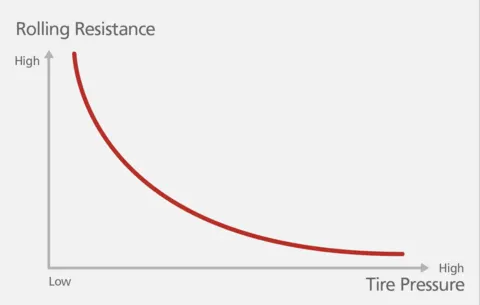
The change in tyre pressure and weight can affect the value of rolling resistance force. the relation between the tyre pressure and rolling resistance is given by,
Tyre Pressure:
An aircraft tire or tyre is designed to withstand extremely heavy loads for short durations.The number of tires required for aircraft increases with the weight of the aircraft, as the weight of the airplane needs to be distributed more evenly. Aircraft tire tread patterns are designed to facilitate stability in high crosswind conditions, to channel water away to prevent hydroplaning, and for braking effect.
Aircraft tires also include fusible plugs which are assembled on the inside of the wheels that are designed to melt at a certain temperature. Tires often overheat if maximum braking is applied during an aborted takeoff or an emergency landing. The fuses provide a safer failure mode that prevents tire explosions by deflating in a controlled manner, thus minimizing damage to aircraft and objects in the surrounding environment.
Aircraft tires are usually inflated with nitrogen to minimize expansion and contraction from extreme changes in ambient temperature and pressure experienced during flight.
Tests of airliner aircraft tires have shown that they are able to sustain pressures of maximum 800 psi (55 bar; 5,500 kPa) before bursting.
Aircraft tires generally operate at high pressures, Inflation up to 200 psi (14 bar; 1,400 kPa) for airliners, and even higher for business jets.
The Tyre Pressure should be maintained as High as possible to maintain the rolling resistance force low.
Brake Forces when landing
Bringing at aircraft down to the runway from 37,000 feet is only part of the challenge. It's not over until the aircraft is safely parked at its gate. In order to do this, pilots have a number of systems available to slow the aircraft down, even in a blizzard on a snow-covered runway.
The 787 braking system
Stopping a 200-tonne aircraft landing at 180 mph requires a lot of braking force. To do this, the 787 has one brake unit on each of the eight wheels on the main gear assembly. On other aircraft types, the brake units are powered by the hydraulics system. An electrical signal is sent from the flight deck to hydraulic actuators near the main landing gear. Here, hydraulic fluid at 3,000 pound per square inch is used to force the brake unit against the wheel, thus slowing it down.This system works fine, but the pipes and actuators that form this part of the hydraulic system come at a considerable weight cost. Extra weight means more fuel burn, which in turn increases costs and carbon emissions. What if the brakes could be powered a different way?
That’s the case on the 787 Dreamliner. Designers did away with the use of the hydraulic system and all its associated architecture and instead used electricity to power the brakes. When the pilots press on the brake pedals, an electrical signal is sent to the brake unit on the wheel. Here, electrically powered actuators are used to press the carbon brake disc against the wheel, slowing it down.
By changing to electric brakes, a 787-8 saves 141 pounds per aircraft and a 787-9 saves 245 pounds. The brakes are also known as "plug and play" because electrical wiring replaces the traditional hydraulics and it’s much easier and quicker to change the brake units when needed. Smart features also allow engineers to monitor the brake performance more closely, giving a real-time measurement of wear on the carbon disks.
Electric brakes
The brake system on the 787 Dreamliner is controlled by the pilots pressing the tops of the rudder pedals under their feet, demanding the rate of braking which they require. This sends an electronic signal to the Left and Right Brake System Control Units (BSCUs).
These then send signals to the four Electronic Brake Actuator Controllers (EBAC) which control the rate of braking on the wheels. Each wheel has four Electric Brake Actuators (EBA), a kind of piston which presses against the carbon brake discs.
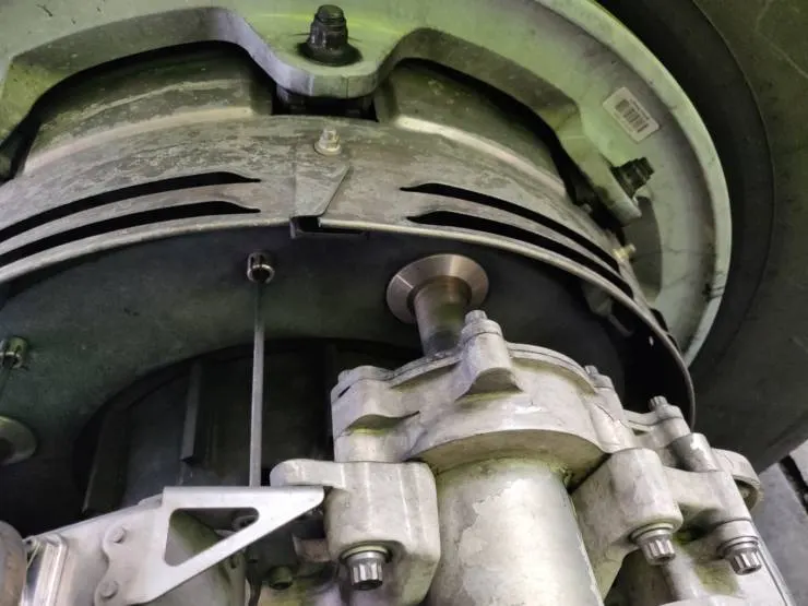
An Electric Brake Actuator (EBA) pressing against the brake disc.
The brake disks themselves are made up of two parts. Firstly, there are the rotors. These are connected to the wheel by drive tabs. As these drive tabs are in contact with the inside of the wheel, they spin at the same speed. Depending on the brake manufacturer, there are either four or five of these rotors on each brake assembly.
The second part of the disks are the stators. These sit around each rotor and are fixed in place and thus don't move. As the wheel turns, the rotors spin round inside the stators.
When the brakes are applied, the four EBAs apply pressure to the first stator. This in turn squeezes the stationary stators up against the spinning rotors and it's this friction which slows the wheel down.
Anti-skid protection
When landing on slippery runways, there's a chance that the wheels may start to skid as the brakes are applied. To stop this from happening and to maintain maximum effective braking, each wheel has anti-skid protection.
Using a variety of sources to determine the aircraft speed, the brake units know how fast the wheels should be spinning. If that speed drops significantly, it's because the current brake pressure on that wheel is too great and the wheel is just skidding over the surface.
In this situation, the anti-skid system automatically reduces the braking on that wheel to a point where the skid stops before reapplying the pressure. All this is done in a fraction of a second.
Autobrake
Pressing on the brakes is pretty straight forward when taxiing in a straight line at low speed. However, when we're landing in strong winds, it can be a little tricky. We need to use our feet on the rudder pedals to line the nose of the aircraft up with the runway centerline at the last moment. Then, whilst holding that position, slide our feet up to press the toe brakes. Really not very easy when moving at 160 mph.
To help us get the braking underway as soon as we touch down, we have the autobrake system.This provides automatic braking at a preselected rate as soon as the aircraft senses that it is on the ground. It also provides full braking pressure in the case of a rejected takeoff if the speed is above 85 knots (98 mph).
Brake temperature indication
With friction comes heat. As a result, each brake unit displays its temperature on the wheel synoptic page in the flight deck. Here, numerical values relating to brake temperature are shown next to each wheel. A value of 0-4.9 is in the normal range. When a temperature becomes 5.0 or above, an advisory message is displayed to the pilots.
Should the brakes become too hot, there's a chance that the heat transferred to the wheels could cause the tires to explode. To stop this from happening, when a certain temperature is reached, fuse plugs in the tires melt. This allows the air to be released safely and slowly deflate the tires.
Parking brake
Every so often we need to engage the brakes and keep them on. This is particularly useful on long taxis to the runway and obviously when parked at the gate. The park brake is set by fully pressing down both toe brakes and pulling the parking brake lever up. With this set, we can then release the pressure from the pedals. To release, we just press the brake pedals again.
In addition to the brakes, there are two other systems which help slow the aircraft down on landing. The spoilers and the reverse thrust.
Spoilers
Have you noticed the large panels on the top of the wings raise up on touch down? These are the called the spoilers as they literally spoil the airflow over the wing. This dumps any remaining lift the wings are generating, allowing the wheels to take all the weight and achieve maximum efficiency from the brakes.
Reverse thrust
The final part of the braking process comes from reverse thrust. Just after we have touched down, we pull two levers on top of the thrust levers to engage the reverse thrust, a sort of "reverse gear" for jet engines.
This causes blockers inside the engine to deploy and a door in the side of the engine to slide backward. The air which normally leaves the engine out the back is deflected forward by the blockers and out through the door.
There are two stages of reverse thrust -- idle reverse and max reverse. Idle reverse is used on most landings and max reverse is used when the landing performance requires it, normally when the aircraft is landing at hot or high elevation airfields.
This forward directed airflow helps slow the aircraft down but is most efficient at high speeds. If using max reverse, we drop this down to idle reverse at 60 knots (70 mph) and then back to normal thrust as we vacate the runway at around 20 knots (25 mph).
Conclusion:
Bringing an aircraft to a safe stop is the most important part of a flight. In order to do this, pilots have a number of facilities available to them.
The brakes bear the brunt of the hard work with the spoilers and reverse thrust lending a helping hand to ensure maximum efficiency. The autobrake system helps keep the deceleration nice and smooth whilst the anti-skid system reduces the distances needed to stop by modulating the brakes on individual wheels and stopping them from skidding.
Aircraft can also depart with part of the braking system not working. By carrying out a performance calculation before every takeoff and landing, we ensure that the aircraft will stop safely in the given conditions, even at maximum takeoff weight.
part B:
Study#6.A):
calculating the force and power required to push / pull an aircraft by a towing vehicle:
Let us assume,
Weight of the aircraft (Boeing 737-8) (m)= 447,700 Kg
Rolling resistance coefficient of aircraft tyre (Crr)= 0.005
Weight of the towing vehicle (m)= 10100 Kg
Rolling resistance coefficient of towing vehicle (Crr) = 0.0025
Rolling resistance force(Frr) = m*Crr*9.8
Rolling resistance force of Aircraft (Frr) =447,700*0.005*9.8
Rolling resistance force of Aircraft (Frr) = 21937.3 N
Rolling resistance force of towing vehicle (Frr) =10100*0.0025*9.8
Rolling resistance force of towing vehicle (Frr)=247.45 N
Total Rolling resistance force (Frr) = 21937.3 + 247.45
Total Rolling resistance force (Frr) =22.185 kN
Calculating Aero Dynamic Drag Force:
Aerodynamic drag is a function of vehicle speed V, vehicle frontal area Af, shape of the vehicle, and air density ρ.
Aerodynamic drag is expressed as
Fad=0.5*ρ*Af*Cd*(V)^2,
where Cd is the aerodynamic drag coefficient that characterizes the shape of the vehicle.
Let us assume,
aircraft and towing vehicle speed (V)=30 kmph = 8.33 m/s
Frontal Area of Aircraft (Af) = 180 m^2
Co-efficient of Drag (Cd) of aircraft = 0.03
air density (ρ) = 1.25 kg/m^3
Aerodynamic drag (Fad) of aircraft=0.5*1.25*180*0.03*(8.33)^2
Aerodynamic drag (Fad) of aircraft= 234.1875 N
Frontal Area of towing vehicle (Af) = 2 m^2
Co-efficient of Drag (Cd) of towing vehicle = 1.15
air density (ρ) = 1.25 kg/m^3
Aerodynamic drag (Fad) of towing vehicle = 0.5*1.25*2*1.15*(8.33)^2
Aerodynamic drag (Fad) of towing vehicle = 99.7465 N
Total Aeroidynamic deag force = 234.1875 + 99.7465
Total Aerodynamic deag force (Fad)= 333.934 N = 0.3339 kN
Force Required by motor:
Force required to push / pull an aircraft by a towing vehicle motor = Frr + Fad
Force required to push / pull an aircraft by a towing vehicle motor = 22.185 + 0.3339
Force required to push / pull an aircraft by a towing vehicle motor = 22.5189 kN
Power Required by motor:
Power required by a towing vehicle motor to push / pull an aircraft = Force * speed in m/s
Power required by a towing vehicle motor to push / pull an aircraft = 22518.9 * 8.33
Power required by a towing vehicle motor to push / pull an aircraft at an average speed of 30 kmph = 187.582 kW
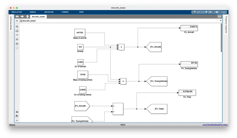
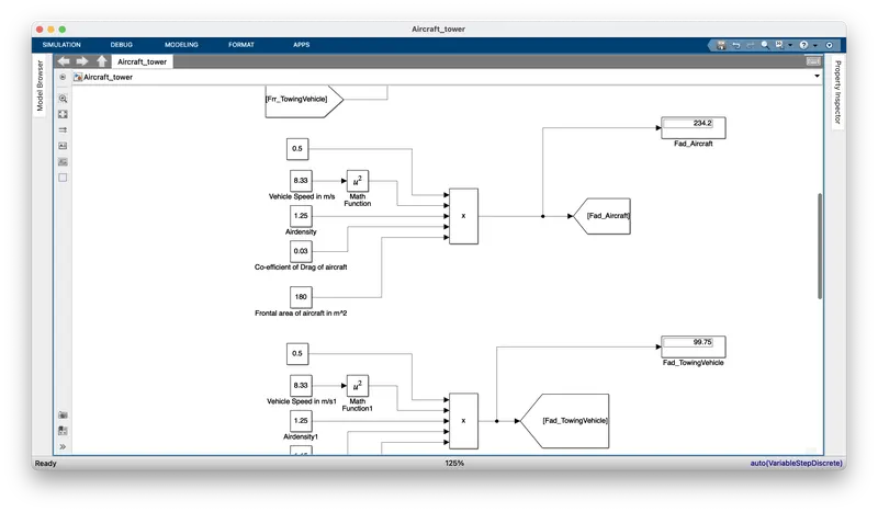
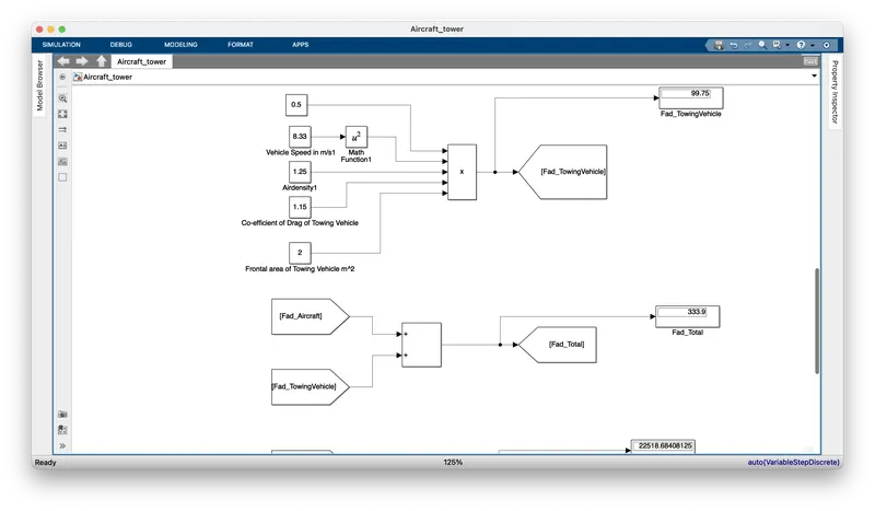
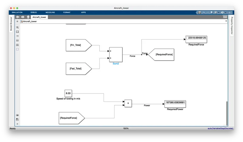
Study#6B: model for the calculated force and power using Simulink
Study 7a):
| Parameters | Assumed Values |
| Mass of Aircraft | 447700 kg |
| coefficeient of rolling resistance for aircraft | 0.005 |
| Mass of towing vehicle | 10100 kg |
| coefficeient of rolling resistance for towing vehicle | 0.0025 |
| Air Density | 1.25 kg/m^3 |
| Co-efficient of drag of aircraft | 0.03 |
| co-efficient of drag of towing vehicle | 1.15 |
| Frontal area of aircraft | 180 m^2 |
| Frontal area of towing vehicle | 2 |
| Operational time of the Towing | 0.5 hours |
From above parameters the required power for towing vehicle is 187.58 kW
Energy Calculations:
Energy = power * time
Energy = 187.58*0.5
Energy required for towing an aircraft =93.79 kWh
Battery Capacity:
The battery capacity for the towing vehicle should be more than 95kWh
Motor selection:
3-pase squirel cage induction motor is used for towing vehicle with specifications below:
| Power | 200KW/270HP |
| Brand | SIEMENS |
| Phase | 3 phase |
| Speed | 1500 |
| Voltage | 415 |
| Mounting Type | FOOT |
| Motor Brand | SIEMENS |
| Motor Voltage | 415 |
Duty Cycle Calculation:
Duty Cycle = (output power/input power)*100
Duty Cycle = (187.58/200)*100
Duty Cycle = 93.79
The Duty Cycle range to control the aircraft speed from zero to highest is 0 to 93.79%
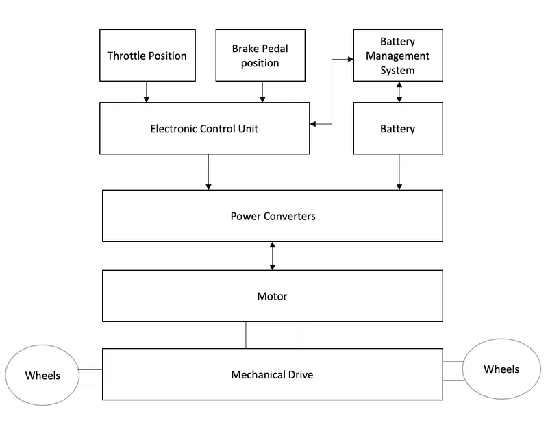
Block Diagram of power Train:
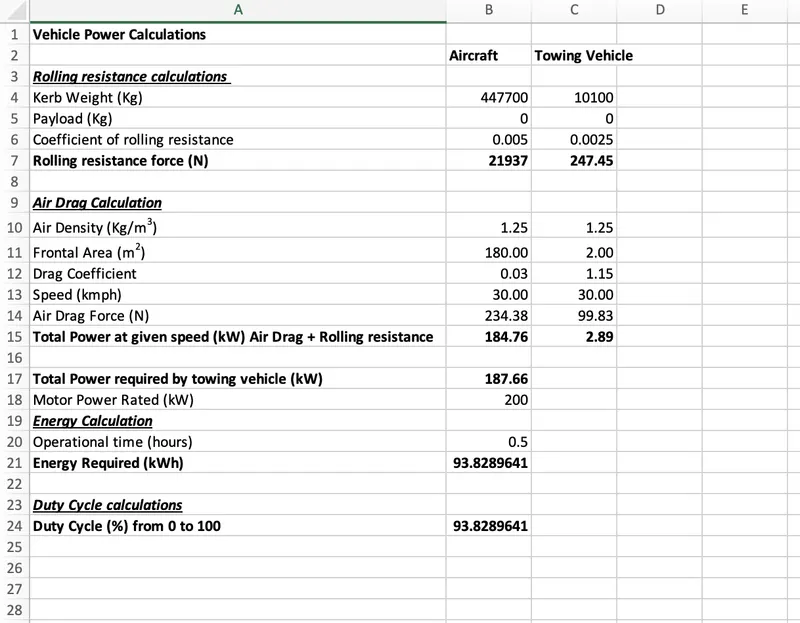
Study: 7 b):
Parameters in excel sheet:
Conclusion:
Designed an electric powertrain with Squirel cage induction motor, it’s power rating, and energy requirement to fulfill aircraft towing application in Simulink. Also estimated the duty cycle range to control the aircraft speed from zero to highest as 93.82 %. Also designed the parameters in excel sheet.