Week-6 Challenge: EV Drivetrain
Question#1:
Types of power converter circuits are employed in electric and hybrid electric vehicle are as follows:
Power converters is a very essential part for both Electric and Hybrid Electric Vehicle as the voltage level of the components like battery, fuel Cell and ultra capacitors should be matched with the voltage level of the DC link. For this purpose DC-DC converters are used.
And an Induction motor in the EV or HEV should have to be powered with an AC supply for this DC-AC converters are used. It is also called as Inverter Circuit.
And AC-DC converters are used for charging the EV or HEV battery from AC power supply. It is also called as Rectifiers.
The most common DC/DC converters can be grouped as follows:
- Non-isolated Converters
- Isolated Converters
- i) Non-isolated converters:
The non-isolated converters type is generally used where the voltage needs to be stepped up or down by a relatively small ratio (less than 4:1). And when there is no problem with the output and input having no dielectric isolation. There are five main types of converter in this non-isolated group, usually called the buck, boost, buck-boost, Cuk and charge-pump converters. The buck converter is used for voltage step-down, while the boost converter is used for voltage step-up. The buck-boost and Cuk converters can be used for either step-down or step-up. The charge-pump converter is used for either voltage step-up or voltage inversion, but only in relatively low power applications.
- Buck Converter :
A Buck converter steps down a DC voltage from the input to the output. The circuit operation depends on the conduction state of the MOSFET: On-state: The current through the inductor increases and the diode blocks. The output voltage of an ideal buck converter is equal to the product of the switching duty cycle and the supply voltage.
- Boost Converter :
Boost Converter is used to convert the DC voltage from lower level to higher level. The key principle that drives the boost converter is the tendency of an inductor to resist changes in current by either increasing or decreasing the energy stored in the inductor magnetic field. In a boost converter, the output voltage is always higher than the input voltage.
- Buck-Boost Converter
The buck–boost converter is a type of DC-DC Converter that has an output voltage magnitude that is either greater than or less than the input voltage magnitude. This is a switched-mode power supply with a similar circuit topology to the Boost Converter and the Buck Converter. The output voltage is adjustable based on the duty cycle of the switching transistor. The output of the buck-boost converter is reversed and the output current ripple is still significant in the topology. Input current and charging current of the capacitor is discontinuous which leads to EMI issues. To overcome these drawbacks Cuk Converter was designed.
- Cuk Converter
The Cuk converter is a DC- DC-based power electronic buck-boost converter with low ripple current named after Slobodan Cuk as its Inventor. The Cuk converter was designed to overcome the drawbacks observed in the buck-boost converter.
The main advantage of this converter is the continuous currents at the input and output of the converter.
The main disadvantage is the high current stress on the switch.
- SEPIC Converter
The single-ended primary-inductor converter (SEPIC) is a type of DC/DC converter that allows the electrical potential (voltage) at its output to be greater than, less than, or equal to that at its input. The output of the SEPIC is controlled by the duty cycle of the control switch (S1).
A SEPIC is essentially a boost converter followed by an inverted buck-boost converter, therefore it is similar to a traditional buck-boost converter, but has advantages of having non-inverted output (the output has the same electrical polarity as the input), using a series capacitor to couple energy from the input to the output (and thus can respond more gracefully to a short-circuit output), and being capable of true shutdown: when the switch S1 is turned off enough, the output (V0) drops to 0 V, following a fairly hefty transient dump of charge.
SEPICs are useful in applications in which a battery voltage can be above and below that of the regulator's intended output. For example, a single lithium ion battery typically discharges from 4.2 volts to 3 volts; if other components require 3.3 volts, then the SEPIC would be effective.
ii) Isolated converters:
Usually, in this type of converters a high frequency transformer is used. In the applications where the output needs to be completely isolated from the input, an isolated converter is necessary. There are many types of converters in this group such as Half-Bridge, Full-Bridge, Fly-back, Forward and Push-Pull DC/DC converters. All of these converters can be used as bi-directional converters and the ratio of stepping down or stepping up the voltage is high.
Question#2:
Given Data:
Battery pack voltage (V) = 72V
Rated armature current (Ia) = 400 A
Armature Resistance (Ra) = 0.5Ω
Motor constant (KΦ) = 0.7 Volt second
Chopper Switching frequency= 400 Hz
Duty Cycle = 70%= 0.70
Tv=24.7+(0.0051)*w2
Solution: -
Applied Terminal Voltage (Vt) to the motor is given by: -
Vt = Battery Voltage (V) * Duty Cycle
Vt = 72 * 0.70
Applied Terminal Voltage (Vt)= 50.4V
Motor torque equation is given by: -
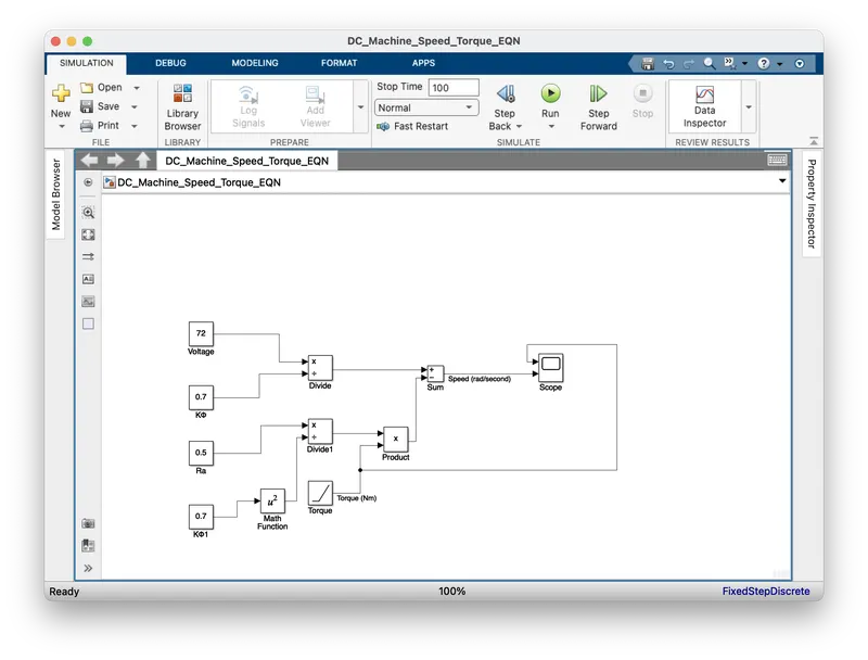
Tm=(Vt* KΦ/Ra)-(w* KΦ2/Ra)
Where;
Tm = Motor Torque (N-m)
Vt = Terminal Voltage (Volts)
ω= steady state speed of vehicle (rps)
K∅= Motor constant
Ra= Armature Resistance
Substituting all these values in equation, we get:
Tm=(50.4*0.7/0.5)-(0.72*ω/0.5)
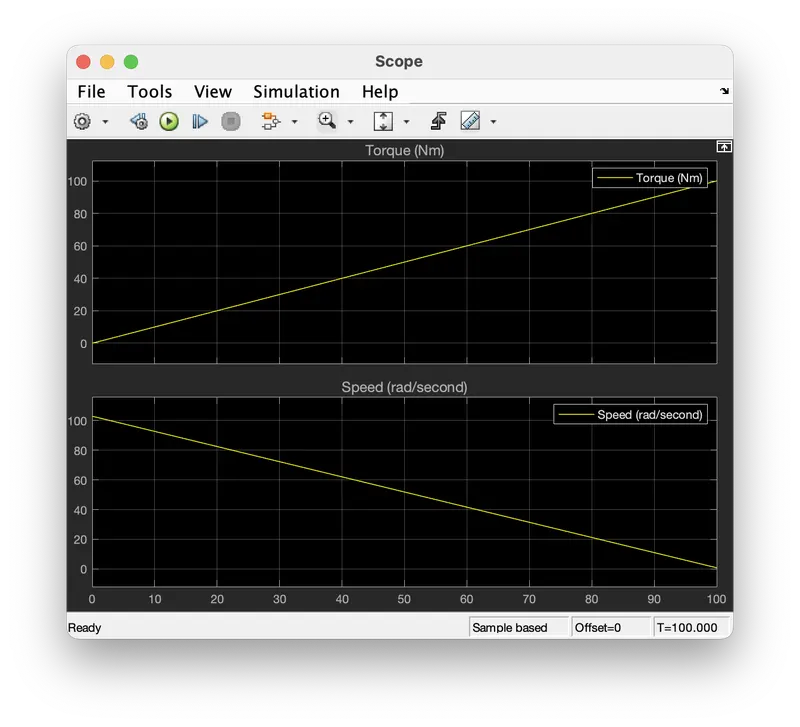
Tm=70.56-0.98ω
In steady state, Motor torque(Tm) should be matched with the Vehicle required torque (Tv),
Hence, Tm=Tv
70.56-0.98ω=24.7+(0.0051)*ω2
00.0051*ω2+0.98*ω-45.86=0
On solving the above equation, we get:
ω= 38.91 rad/s and ω= -231.07 rad/s
We take the positive value;
Steady state speed of vehicle = = 38.91 rad/s
Steady state speed of vehicle in RPM = 9.549297*38.91
Steady state speed of vehicle in RPM = 371.56 RPM
Question#3:
Question#4:
According to author DC brushless drives are efficient than a induction drive due to the following reasons:
- Both DC brushless and induction drives use motors having similar stators. Both drives use 3-phase modulating inverters. The only differences are the rotors and the inverter controls. And with digital controllers, the only control differences are with control code. (DC brushless drives require an absolute position sensor, while induction drives require only a speed sensor; these differences are relatively small.)
- One of the main differences is that much less rotor heat is generated with the DC brushless drive. Rotor cooling is easier and peak point efficiency is generally higher for this drive. The DC brushless drive can also operate at unity power factor, whereas the best power factor for the induction drive is about 85 percent. This means that the peak point energy efficiency for a DC brushless drive will typically be a few percentage points higher than for an induction drive.
- In an ideal brushless drive, the strength of the magnetic field produced by the permanent magnets would be adjustable. When maximum torque is required, especially at low speeds, the magnetic field strength (B) should be maximum – so that inverter and motor currents are maintained at their lowest possible values. This minimizes the I²R (current² resistance) losses and thereby optimizes efficiency. Likewise, when torque levels are low, the B field should be reduced such that eddy and hysteresis losses due to B are also reduced. Ideally, B should be adjusted such that the sum of the eddy, hysteresis, and I² losses is minimized. Unfortunately, there is no easy way of changing B with permanent magnets.
- In contrast, induction machines have no magnets and B fields are “adjustable,” since B is proportionate to V/f (voltage to frequency). This means that at light loads the inverter can reduce voltage such that magnetic losses are reduced and efficiency is maximized. Thus, the induction machine when operated with a smart inverter has an advantage over a DC brushless machine – magnetic and conduction losses can be traded such that efficiency is optimized. This advantage becomes increasingly important as performance is increased. With DC brushless, as machine size grows, the magnetic losses increase proportionately and part load efficiency drops. With induction, as machine size grows, losses do not necessarily grow. Thus, induction drives may be the favoured approach where high-performance is desired; peak efficiency will be a little less than with DC brushless, but average efficiency may actually be better.
- Permanent magnets are expensive, This means that induction motors will likely retain a cost advantage over PM machines. Also, due to the field weakening capabilities of induction machines, inverter ratings and costs appear to be lower, especially for high performance drives. Since spinning induction machines produce little or no voltage when de-excited, they are easier to protect.
- Induction machines are more difficult to control. The control laws are more complex and difficult to understand. Achieving stability over the entire torque-speed range and over temperature is more difficult with induction than with DC brushless. This means added development costs, but likely little or no recurring costs.
Conclusion:
The author concludes both machines are best in their own way as per the requirement. DC brushless drives will likely continue to dominate in the hybrid and coming plug-in hybrid markets, and that induction drives will likely maintain dominance for the high-performance pure electrics.