Project-1: Powertrain for aircraft in runways
| Project-1: Powertrain For Aircraft In Runways |
PART - A
___Q1___
Search and list out the total weight of various types of aircrafts.
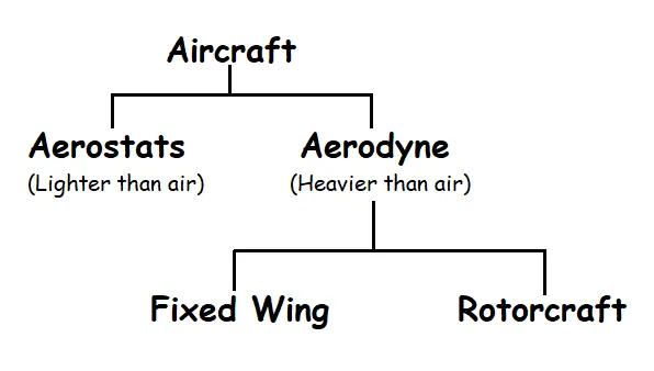
----> Aircrafts are classified as follows :-
| A) Aerostats | |
|
Blimp - It is an airship without an internal structural framework. It relies on the pressure of the lifting gas (usually helium) inside the envelope and the strength of the envelope itself to maintain their shape. Empty Weight (EW) - 8850 kg Max Take Off Weight (MTOW) - 408 kg |
 |
|
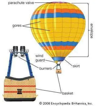
Hot Air Balloon - It consist of an envelope which contains heated air. Suspended beneath is a basket for passengers and a heat source. EW - 1000 kg. |
 |
| B) Aerodyne | |
|
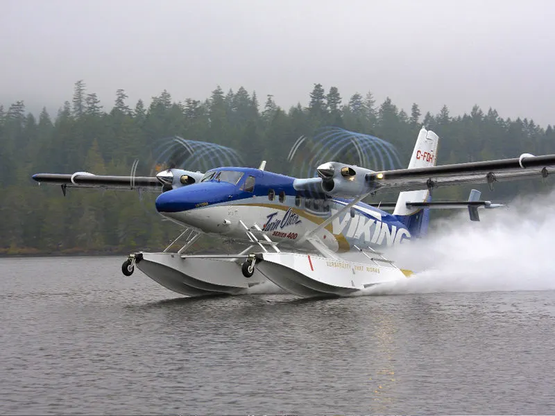
Amphibious Aircraft - It is an aircraft that can off and land on both solid ground and water . EW - 3500 kg. MTOW - 700 kg. |
 |
|
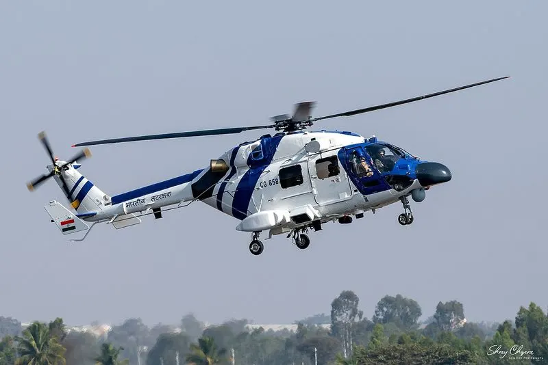
Helicopters - The horizontally rotating rotors provide and assist in lifting and thrusting the helicopter. These aircraft have the advantage of being carried vertically, horizontally, and flying both backward and forwards or laterally. EW - 4500 kg. MTOW - 1300 kg. |
 |
|
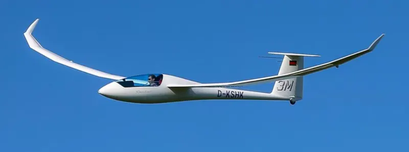
Glider - This unpowered aircraft can use naturally occurring currents of rising air in the atmosphere to gain altitude. EW - 250 kg. MTOW - 200 kg. |
 |
|
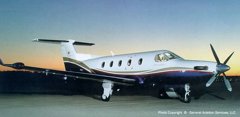
Turboprop - Turboprop aircraft have one or more gas-turbine engines connected to a gearbox that turns the propeller(s), to move the aircraft on the ground and through the air. EW - 3000 kg. MTOW - 1700 kg. |
 |
|
Jet - They are propelled by jet engines. Jet engines achieve maximum efficiency at speeds close to or even well above the Speed of sound. Jet aircraft generally cruise most efficiently at about Mach 0.8 . EW - 11,000 kg. MTOW - 16,000 kg. |
 |
|
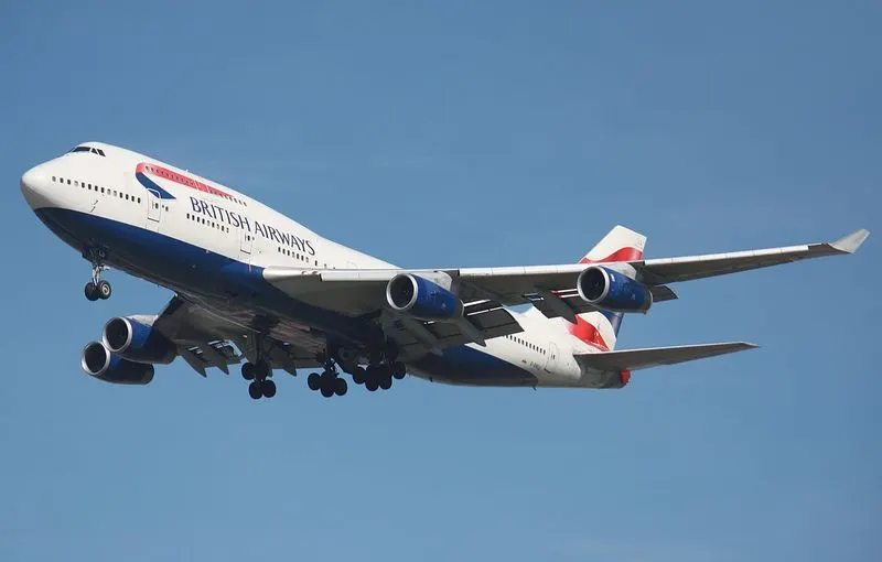
Airliner (commercial plane) - It is intended for carrying multiple passengers or cargo in commercial service.They are powered by turboprop or turbofan. EW - 1,80,000 kg. MTOW - 10,000 kg. |
 |
|
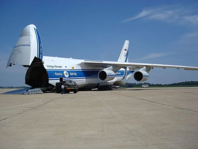
Cargo Aircraft - It is designed or converted for the carriage of cargo rather than passengers. EW - 2,00,000 kg. MTOW - 3,00,000 kg. |
 |
|
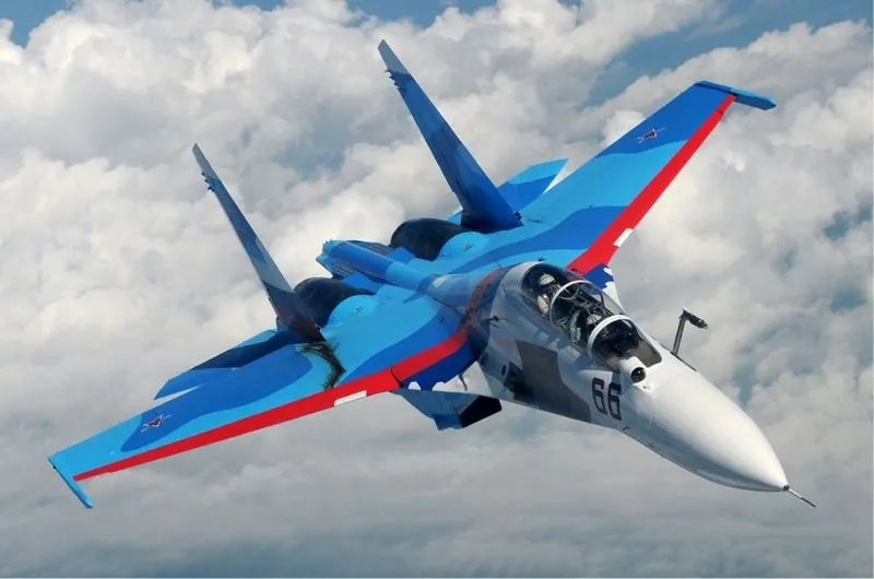
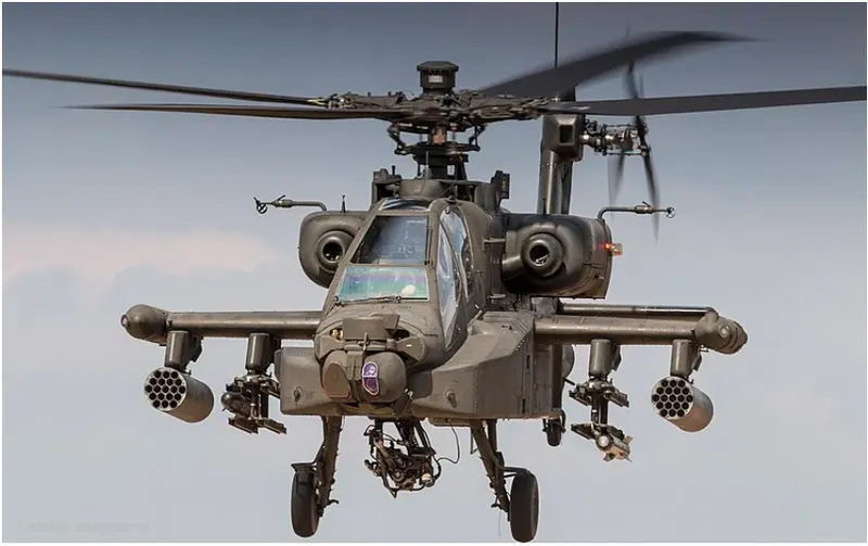
Military Fighter Aircraft - It can be fixed wing or rotary wing, designed primarily for air-to-air combat. EW - Fixed wing - 20,700 kg. (Su-30) Rotary wing - 5165 kg. (Apache) MTOW - Fixed wing - 10,000 kg. (Su-30) Rotary wing - 4000kg. (Apache) |
|
|
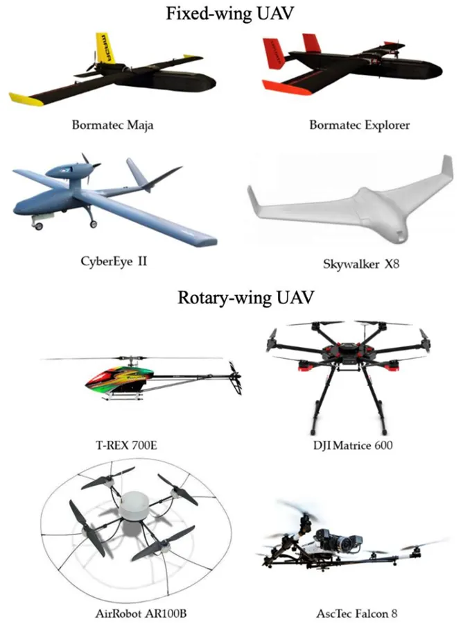
UAV/ Drone - An aircraft wihtout any human pilot, crew or passengers on board. They are remotely piloted aircraft. They have military (surveillance, strike) and non-military uses (photography, delivery, policing). Weight - 250g to >250 kg. |
 |
___Q2___
Is there any difference between ground speed and air speed?
---->
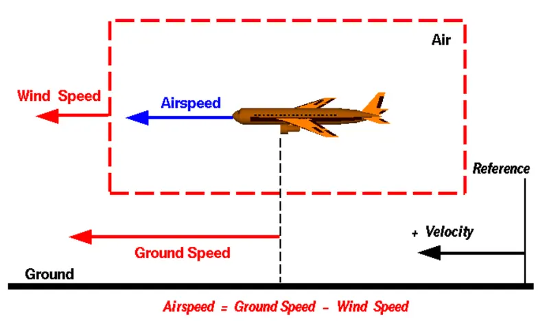
Groud Speed : - Airplanes speed relative to the surface of the Earth.
- It determines how fast the airplane will reach its destination.
- It is sum of air speed and wind speed.
Air Speed : - Airplanes speed relative to the air in which it is flying.
- It is a gauge of presence of enough air flow around the plane to fly.
- The difference of ground speed and wind speed is air speed.
___Q3___. Why is it not recommended to use aircraft engine power to move it on the ground at Airport?
___Q4___. How an aircraft is pushed to runway when its ready to take off?
---->
- When an aircraft's engine is activated, the thrust can create a high-speed wind that can easily cause damage to the airport terminal, surrounding ground vehicles, jetway, baggage and most importantly, ground personnel.
- Engine thrust can easily send any loose items airborne, turn the tiniest grains of dust into hazardous projectiles and create debris that can cause damage to multi-million dollar engines.
- Aircraft engines generate extreme noise that can be harmful to ground personnel.
Thus the aircraft is pushed using a pushback or towing vehicle called as taxing.
- It makes general maintenance easier for ground staff.
- Towing vehicle driver has better ground view than from a cockpit.
- Towing vehicle can easily move the aircraft in backward/reverse direction.
- Using a towing vehicle is more economical and safer option.
___Q5___
Learn about take off power, tyre design, rolling resistance, tyre pressure, brake forces when landing.
---->
Take-off Power
- The amount of power that an engine is allowed to produce for a limited period of time for takeoff.
- Take off power is almost never maximum engine power.
- Maximum power affects engine life as it brings significant wear to the engine, high noise level, higher fuel consumption.
- Instead, takeoff performance is calculated and the appropriate thrust setting is used.
- Lower settings are needed when - runway is long, no obstacle to clear during climb, runway is dry, temperature is low, head wind is fast.
Take off performance.
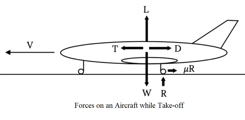 |
W = Weight of aircraft R = Rolling Resistance L = Lift Force T = Thurst Force D = Drag Force |
Vertical forces : R = W - L
Horizontal forces : `m(dv)/dt = T - D - muR`
These forces change as the aircraft accelerates from rest to take-off speed.
combining the two forces we get the acceleration required
| `m(dv)/dt = T - D - mu(W - L)` |
Tyre Design
An aircraft tyre is designed to withstand extremely heavy loads while landing, take off, taxing, and parking. The number of wheels required for aircraft increases with the weight of the aircraft, as the weight of the aeroplane needs to be distributed more evenly.They help to absorb the shock of landing and provide cushioning. It also provides the necessary traction for braking and stopping of an aircraft.
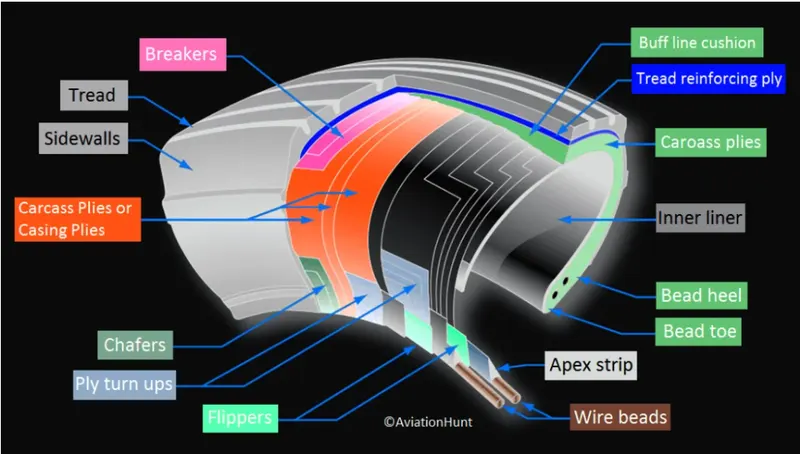
Figure above shows tyre construction.
Tread - It is the wearable part of the tyre that comes into contact with the ground. It is located on the tyre crown. It resist frictional wear, abrasion, cracking and curts that occur due to landing surface and condition of runway.
Sidewall - It is a protective layer that covers the outer casing ply. It extends from the tread edge to the bead area.
Tread Reinforcing Ply - One or more layers of fabric that strengthens and stabilizes the tread area for high-speed operation.
Buff Line Cushion - It enhances the adhesion between the tread reinforcing ply and the breakers or casing plies. It is of sufficient thickness to allow for the removal of the old tread when the tyre is retreaded.
Breakers - Breakers are reinforcing plies of rubber-coated fabric placed under the buff line cushion to protect casing plies and strengthen and stabilize the tread area.
Casing Plies - Alternate layers of rubber-coated fabric (running at opposite angles to one another) provide the strength of the tyre.
Wire Beads - Hoops of high tensile strength steel wire that anchor the casing plies and provide a firm mounting surface on the wheel.
Flippers - Layers of rubberized fabric that help anchor the bead wires to the casing and improve the durability of the tyre.
Tube or Tube-less - Tubeless tyres are more advantageous over tube-type. Tube-less are infalted with nitrogen gas, as it is less affected by extreme changes in temperature and pressure due to contraction and expansion.
Load Rating – Load rating is the maximum permissible load at a specified inflation pressure.
Speed Rating – The speed rating is the maximum takeoff speed to which the tyre has been tested.
Skid Depth – Skid depth is the distance between the tread surface and the deepest groove as measured in the mould.
Each tyre manufacturer produces their own designs of the tyre with different tread patterns, wear patterns, wear limits etc.But all tyres must meet the approved standards before being accepted by the Federal Aviation Administration(FAA).
Rolling Resistance
It is a force that resists the motion of a body rolling on a surface. Also called as rolling friction.
In an aircraft it is affected with : Tyre diameter and width.
Tyre pressure.
Aircraft weight over tyre axle.
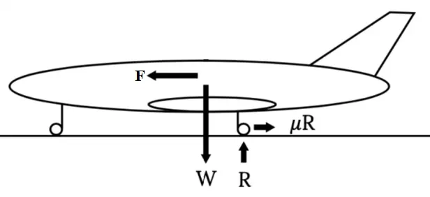
The Rolling Resistance can be expressed as -
|
`R = mu W` ......(1) where, R = Rolling Resistance `mu`= Rolling Resistance Coefficient W = Weight `W = m *a_g` m = mass of body. `a_g` = acceleration due to gravity. Putting in eq (1) `R = mu * m *a_g` |
Rolling Resistance Coefficient is influenced by different variables like wheel design, surface, etc.
|
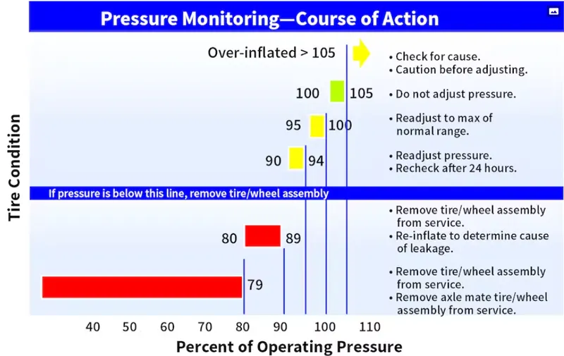
Tyre Pressure
Because aircraft tyres operate at such high extremes of pressure, load, and speed, their care and service is critically important. The most important being tyre inflation pressure. Failure to keep the pressure intact can have serious consequences.
1- If the tyre operates underinflated or overinflated, the nylon cord structure of the tyre may weaken out of in and out compression as the tyre torates.
2- Thrown tread due to under inflation.
3- Overdeflection increases shear between components in the tyre as it rolls in and out of contact and deforms. This results in a more rapid build‐up of heat within the tyre.
The rated conditions are specified by industry standard’s bodies like The Tyre and Rim Association (T&RA) and The European Tyre and Rim Technical Organisation (ETRTO).
Braking Force When Landing
- Braking force is the primary system that stops an aircraft on the ground.
- Brakes are actually energy absorbing devices that remove the enormous amounts of kinetic energy stored in a moving aircraft.
- The kinetic energy of motion is converted to heat through the friction created by the rolling tyres on the runway surface and the pucks, brake disks, being applied to plates fixed to the rotating wheels.
-
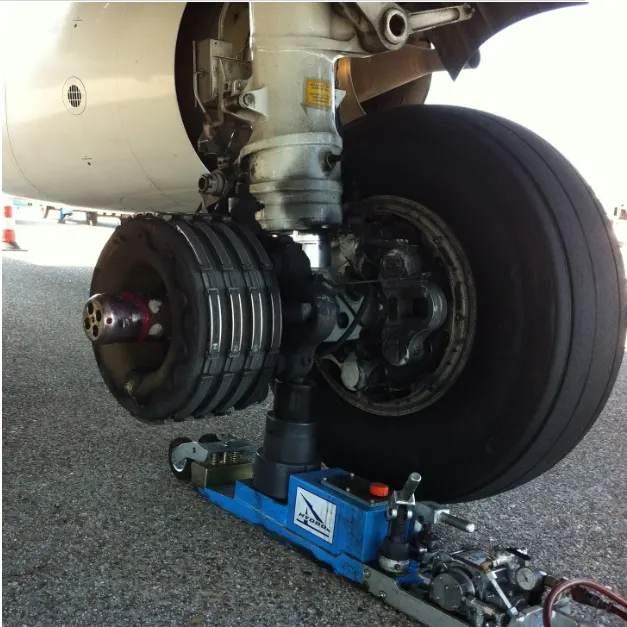
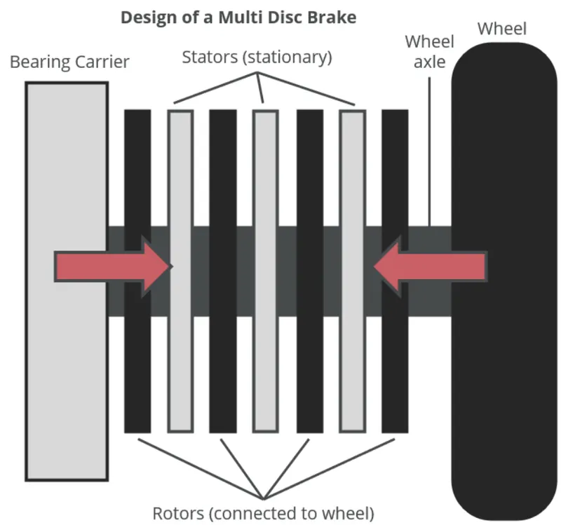
- Force that a brake must produce should be enough to counter the kinetic energy of the aircraft after touchdown.
- The KE is given by `1/2 *m*V^2` where, m is mass of aircraft, V is the velocity.
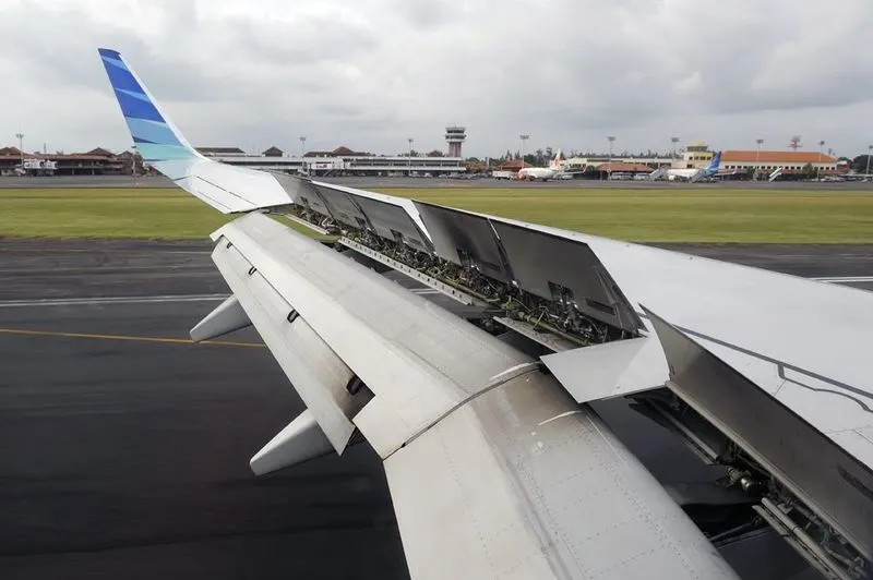
- In Secondary system, Spoilers and Reverse thurst is employed which help slow the aircraft down on landing.
- Spoliers - Large panels on wings that raise up upon touch down. They are called spoilers as they literally spoils the air flow over the wing. They dump any remaining lift the wings are generating.
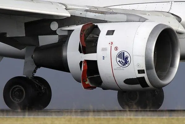
- Reverse Thurst - A door inside of the engine slides backward and spreads like wings. Normally the air which leaves the engine from the back is defelected forward by the door or blockers.
-
Spoilers-
Reverse Thursters -
PART - B
___Q6___ A
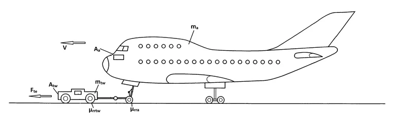
AIM : To calculate the force and power required to push / pull an aircraft by a towing vehicle.
ASSUMPTIONS :
| Mass of Aircraft (`m_a`) | 2,00,000 kg |
| Mass of Towing Vehicle (`m_(tw)`) | 50,000 kg |
| Coefficient of Rolling Resistance of aircraft `(mu_(rra))` | 0.02 |
| Coefficient of Rolling Resistance of towing vehicle (`mu_(rrtw)`) | 0.01 |
| Air Density (`rho`) | 1.225 `kgm^-3` |
| Frontal Area of aircraft (`A_a`) | 400 `m^2` |
| Frontal Area of towing vehicle (`A_(tw)`) | 40 `m^2` |
| Drag Coefficient of aircraft (`C_(da)`) | 0.04 |
| Drag Coefficient of towing vehicle (`C_(dtw)`) | 0.01 |
| Velocity (V) | 3 m/s |
| Acc. due to gravity (g) | 9.81 m/s^2 |
THEORY :
Total Tractive Force (`F_(te)`) = Rolling Resistance Force (`F_(rr)`) + Drag Force (`F_(ad)`)
= Rolling Resistance Force of Aircraft + Towing Vehicle + Drag Force of Aircraft + Towing Vehicle
= `F_(rra) + F_(rrtw) + F_(ada) + F_(adtw)` ................(1)
Total Tractive Power (`P_(te)`) = `F_(te) * V` ...................(2)
Rolling Resistance Force :- `F_(rr) = mu_(rr)*m*g`
`F_(rra) = mu_(rra) * m_(a)*g` = `(0.02)*(200000)*(9.81) = 39240 N`
`F_(rrtw) = mu_(rrtw) * m_(tw)*g` = `(0.01)*(50000)*(9.81) = 4905 N`
Aerodynamic Drag Force :- `F_(ad) = (1/2)*rho*A*C_(d)*V^2`
`F_(ada) = (1/2)*rho*A_(a)*C_(da)*V^2 (1/2)*(1.225)*(400)*(0.04)*(3)^2 = 88 N`
`F_(adtw) = (1/2)*rho*A_(tw)*C_(dtw)*V^2 = (1/2)*(1.225)*(40)*(0.01)*(3) = 2.2 N`
CONCLUSION :
Putting above values in Eq (1)
Total Tractive Force `F_(te)`= 39240 + 4905 + 88 + 2.2 = 44235.2 N`
Total Tractive Power `P_(te)`= 44235.2 * 3 = 132.7 kW
6. B
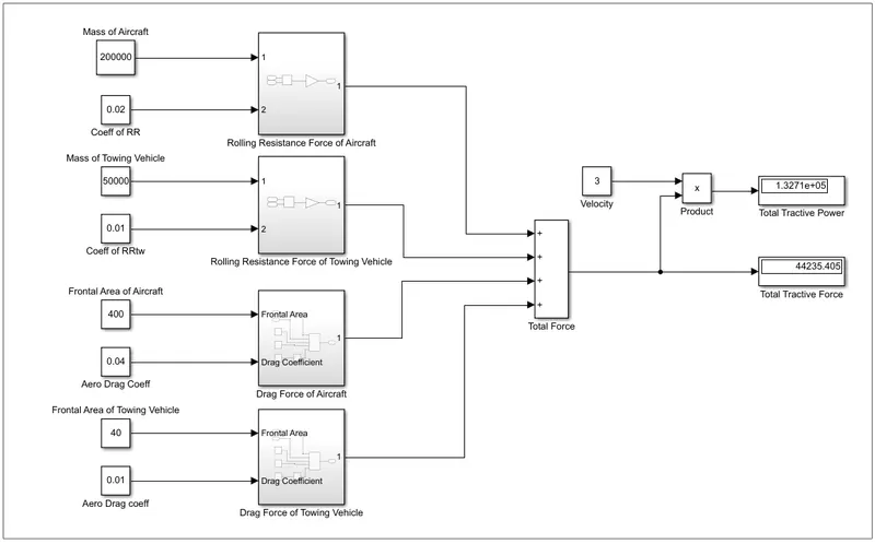
Simulink Model for calculating Force and Power for above example.
- A 'CONSTANT' block is used for mass, coefficient of Rolling resistance, frontal area, drag coefficient, velocity.
- A subsystem is created for calculation of Rolling Resistance Force, has been explained below.
- A subsystem is created for calculation of Drag Force, has been explained below.
- All forces (Rolling Resistance Force & Drag Force) are added using 'ADD' block to get Total Tractive Force, which has been displayed with the help of 'DISPLAY' block.
- Total Tractive Power is calculated by 'PRODUCT' block, velocity * force.
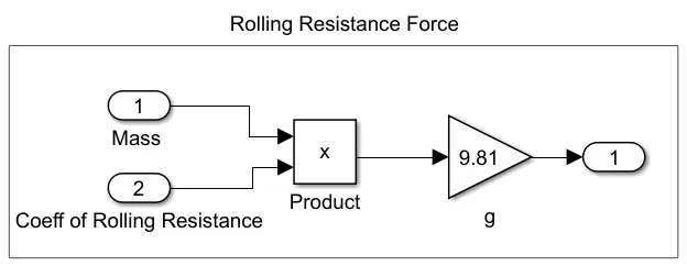 |
Formula used - `F_(rr) = mu_(rr)*m*g` 'PRODUCT' block is used to multiply input values, which is then multiplied with 'GAIN' block . |
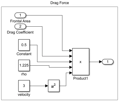 |
Formula used - `F_(ad) = (1/2)*rho*A*C_d*V^2` 'PRODUCT' block is used to multiply input values. 'POWER' block is used to square the input velocity. |
CONCLUSION :
From Simulation we got the same result as calculated in 6.A.
Total Tractive Force = 44235.405 N & Total Tractive Power = 132.7 kW.
___Q7___A
AIM : To design an electric powertrain with a motor, its power rating and energy requirement to fulfill aircraft towing application in Simulink. Estimate Duty Cycle range to control the aircraft speed from zero to higherst.
ASSUMPTIONS :
| 1. Wheel Radius | 29 inch / 0.7366 m |
| 2. Gear Ratio (G) | 8 |
| 3. Transmission Efficiency (`eta_t`) | 85% |
| 4. Motor Speed (`omega`) | 300 rpm / 31.5 rad/sec |
| 5. Time for Towing | 5 minutes. |
THEORY :
Total Tractive Force required for the aircraft to be pulled/pushed = 44.235 kN.
Total Tractive Power required for the aircraft to be pulled/pushed = 132.7 kW.
Assuming the towing time to be - 5 min.
Therefore,
- Energy required for towing = Power required for towing * Time for towing.
`E_(te) = P_(te)*t`
= 132.7 * (5/60) = 11 kWh
- Motor Torque Calculations.
Wheel Torque = Force * radius of wheel.
= (44235) * (0.7366) = 32583 Nm
Motor Torque (`tau_m`) = Wheel Torque / (Gear Ratio * transmission efficiency)
`tau_m`= `tau_w / (G * eta_t)`
= `32583/ (8 * 0.85)` = 4791 kNm
- Motor Power Rating,
`P_m = tau_m * omega`
= 4791 * 31.5 = 150 kW. (Enough for towing vehicle application)
- Duty Cycle Range,
D = `(Required Power) / (Rated Power)`
= 132.7 / 150 = 0.88 = 88%
SIMULINK MODEL -
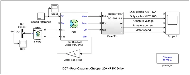
- DC7 block is modified to suit our requirements where AC source is replaced with battery, speed reference is also changed.
- A battery with voltage = 150 V, rated capacity 5.4 Ah is used.
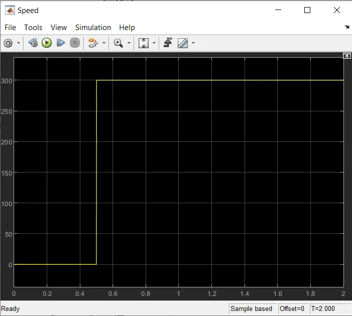
- Speed referenec of 300 rpm is given to drive.
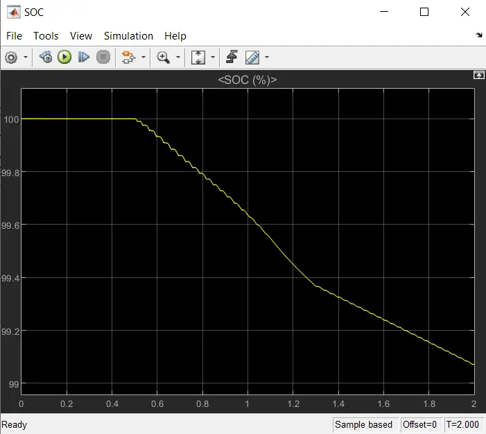
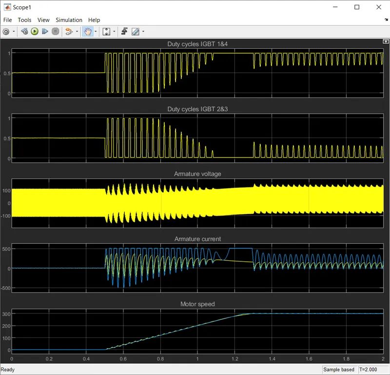
- The simulation is run for 2 seconds and SOC & motor parameters are observed across scope.
OUTPUT :
|
Speed - Rises from 0-300 at 0.5 seconds.
|
SOC - Reduces from 100 to 99 % in 2 sec of towing operation.
|
Scope 1 - IGBT duty cycle i.e. 88% is used to vary armature voltage and current.
Motor speed rises to 300 rpm (rated) in 1.3 seconds.
Till then the IGBT current is varied and then it settles to its nominal value just to maintain the speed at 300 rpm.
7.B
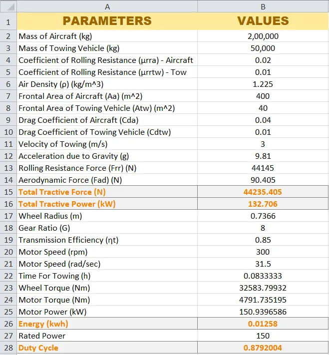
Also, Design the parameters in excel sheet.