Project-1: Powertrain for aircraft in runways
AIM: To study and understand powertrain system of an aircraft.
OBJECTIVE 1: Search and list out the total weight of various types of aircrafts.
MTOW = Maximum take-off weight, MLW = Maximum landing weight,
| Type | MTOW [kg] | MLW [tons] |
| Airbus A220-100 | 59,000 | 50.8 |
| Airbus A220-300 | 65,000 | 57.61 |
| Airbus A300-600[14] | 1,63,000 | 138 |
| Airbus A300-600R[14] | 1,92,000 | 140 |
| Airbus A310-200[14] | 1,42,000 | 123 |
| Airbus A310-300[14] | 1,57,000 | 124 |
| Airbus A318[18] | 59,000 | 57.5 |
| Airbus A319[18] | 64,000 | 62.5 |
| Airbus A320-100[18] | 68,000 | 66 |
| Airbus A321-100[18] | 83,000 | 77.8 |
| Airbus A330-200[12][13] | 2,42,000 | 180 |
| Airbus A330-300[12][13] | 2,42,000 | 185 |
| Airbus A340-200[8][11] | 2,53,500 | 181 |
| Airbus A340-300[8][9] | 2,76,700 | 190 |
| Airbus A340-500[8] | 3,71,950 | 240 |
| Airbus A340-600[8] | 3,67,400 | 256 |
| Airbus A350-900 | 2,70,000 | 175 |
| Airbus A350-1000 | 3,08,000 | 233.5 |
| Airbus A380-800[1][2][3] | 5,75,000 | 394 |
| Airbus A400M | 1,41,000 | 122 |
| Antonov An-124-100M | 4,05,060 | 330 |
| Antonov An-225 | 6,40,000 | 591.7 |
| ATR 42-500 | 18,600 | 18.3 |
| ATR 72-600 | 22,800 | 22.35 |
| Avro RJ-85 | 42,000 | 36.74 |
| BAe Jetstream 41 | 10,890 | 10.57 |
| Beechcraft 1900D | 7,765 | 7.605 |
| Boeing 377 | 67,000 | |
| Boeing 707-120B[15] | 1,17,000 | 86.3 |
| Boeing 707-320B[15] | 1,51,000 | 97.5 |
| Boeing 707-320C[15] | 1,51,000 | 112.1 |
| Boeing 717-200BGW | 50,000 | 46.265 |
| Boeing 717-200HGW | 55,000 | 47.174 |
| Boeing 720[16] | 1,04,000 | 79.5 |
| Boeing 720B[16] | 1,06,000 | 79.5 |
| Boeing 727-100[17] | 72,500 | 62.4 |
| Boeing 727-100C[17] | 72,500 | 62.4 |
| Boeing 727-200[17] | 78,000 | 68.1 |
| Boeing 727-200 Advanced[17] | 84,000 | 70.1 |
| Boeing 737-300 | 63,000 | 51.7 |
| Boeing 737-400 | 68,000 | 54.9 |
| Boeing 737-500 | 60,000 | 49.9 |
| Boeing 737-600 | 66,000 | 54.66 |
| Boeing 737-700 | 70,000 | 58.06 |
| Boeing 737-800 | 79,000 | 65.32 |
| Boeing 737-900 | 85,000 | 66.36 |
| Boeing 737-900ER | 85,000 | 71.35 |
| Boeing 747-8 | 4,43,613 | 306.175 |
| Boeing 747-8F | 4,47,700 | 346.091 |
| Boeing 747-100[7] | 3,40,200 | 265.3 |
| Boeing 747-200[7] | 3,77,840 | 285.7 |
| Boeing 747-300[7] | 3,77,840 | 260.32 |
| Boeing 747-400 | 3,96,900 | 295.742 |
| Boeing 747-400ER | 4,12,770 | 295.742 |
| Boeing 757-200 | 1,16,000 | 89.9 |
| Boeing 757-300 | 1,24,000 | 101.6 |
| Boeing 767-300 | 1,59,000 | 136.078 |
| Boeing 767-300ER | 1,87,000 | 136.08 |
| Boeing 767-400ER | 2,04,000 | 158.758 |
| Boeing 777-200ER | 2,97,550 | 213 |
| Boeing 777-200LR | 3,47,450 | 223.168 |
| Boeing 777-300 | 2,99,370 | 237.683 |
| Boeing 777-300ER | 3,51,800 | 251.29 |
| Boeing 777F | 3,47,800 | 260.816 |
| Boeing 787-8[10] | 2,28,000 | 172.365 |
| Boeing 787-9[10] | 2,54,000 | 192.777 |
| Boeing 787-10[10] | 2,54,000 | 201.849 |
| Bombardier CRJ200 | 23,000 | 21.319 |
| Bombardier CRJ700 | 33,000 | 30.39 |
| Bombardier CRJ900[21] | 36,500 | 33.345 |
| Bombardier Q400 | 28,000 | 28.01 |
| Caravelle III | 46,000 | |
| Cessna Citation CJ4[26] | 7,761 | 7.103 |
| Concorde | 1,85,000 | 111.1 |
| Embraer 120 Brasilia | 11,500 | 11.25 |
| Embraer 170[22] | 36,000 | 32.8 |
| Embraer 175[20] | 37,500 | 32.8 |
| Embraer 190[19] | 48,000 | 43 |
OBJECTIVE 2: Is there any difference between ground speed and air speed?
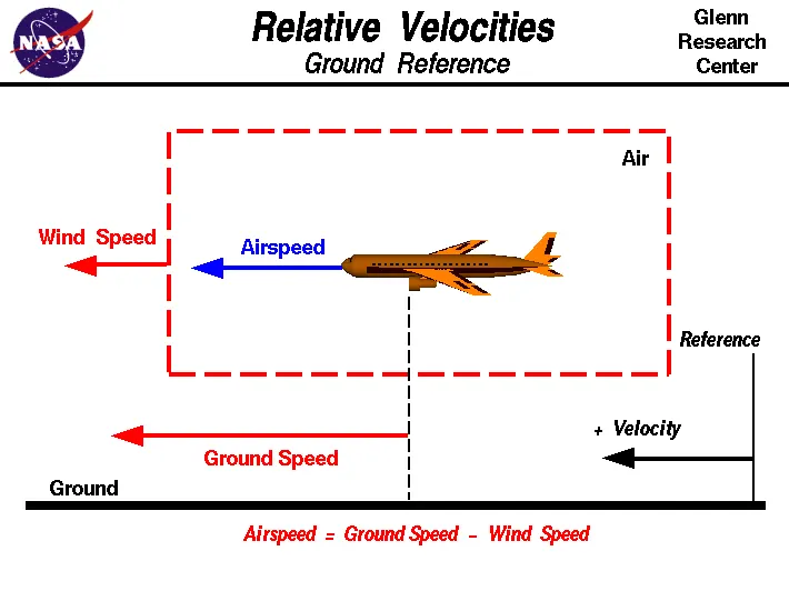
Ground Speed
For a reference point picked on the ground, the aircraft moves relative to the reference point at the ground speed. Ground speed is also a vector quantity so a comparison of the ground speed to the wind speed must be done according to rules for vector comparisons.
Airspeed
The important quantity in the generation of lift is the relative velocity between the object and the air, which is called the airspeed. Airspeed cannot be directly measured from a ground position, but must be computed from the ground speed and the wind speed. Airspeed is the vector difference between the ground speed and the wind speed.
Airspeed = Ground Speed - Wind Speed
On a perfectly still day, the airspeed is equal to the ground speed. But if the wind is blowing in the same direction that the aircraft is moving, the airspeed will be less than the ground speed.
OBJECTIVE 3: Why is it not recommended to use aircraft engine power to move it on the ground at Airport?
Taxiing (rarely spelled taxying) is the movement of an aircraft on the ground, under its own power, in contrast to towing or push-back where the aircraft is moved by a tug. The aircraft usually moves on wheels, but the term also includes aircraft with skis or floats (for water-based travel).
Usually an aircraft taxies under its own power. Aircraft have no powered wheels, so the forward thrust comes from the engines. Only pushback from the gate is mostly done by a tractor, although some aircraft can use reverse thrust for that.
When the aircraft is being moved for maintenance purposes or simply relocation at the airfield, the aircraft is usually pulled.
OBJECTIVE 4: How an aircraft is pushed to runway when its ready to take off?
Takeoff is the phase of flight in which an aircraft goes through a transition from moving along the ground (taxiing) to flying in the air, usually starting on a runway. Usually the engines are run at full power during takeoff. Following the taxi motion, the aircraft stops at the starting line of the runway. Before takeoff, the engines, particularly piston engines, are routinely run up at high power to check for engine-related problems. This makes a consid- erable noise. When the pilot releases the brakes, the aircraft starts accelerating rapidly until the necessary speed for take-off is achieved.
The takeoff speed required varies with air den- sity, aircraft weight, and aircraft configuration (flap and/or slat position, as applicable). Air density is affected by factors such as field ele- vation and air temperature.
Operations with transport category aircraft employ the concept of the takeoff V-Speeds, V1 and V2. These speeds are determined not only by the above factors affecting takeoff perform- ance, but also by the length and slope of the runway. Below V1, in case of critical failures, the takeoff should be aborted; above V1 the pilot continues the takeoff and returns for land- ing. After the co-pilot calls V1, Then, V2 (the safe takeoff speed) is called. This speed must be maintained after an engine failure to meet per- formance targets for rate of climb and angle of climb.
The speeds needed for takeoff are relative to the motion of the air (indicated airspeed). A head wind will reduce the ground speed needed for takeoff, as there is a greater flow of air over the wings. This is why the aircrafts always take off against the wind. Side wind is not preferred as it would disturb the stability of the aircraft. Typical takeoff air speeds for jetliners are in the 130–155 knot range (150–180 mph, 240–285 km/h). For a given aircraft, the takeoff speed is usually directly proportional to the aircraft weight; the heavier the weight, the greater the speed needed. Some aircraft have difficulty generating enough lift at the low speeds encountered during takeoff. These are therefore fitted with high-lift devices, often including slats and usually flaps, which increase the camber of the wing, making it more effective at low speed, thus creating more lift. These have to be deployed from the wing before performing any maneuver.
At the beginning of the climb phase, the wheels are retracted into the aircraft and the undercarriage doors are closed. This operation is audible by the passengers as a noise coming from below the floor.
OBJECTIVE 5: Learn about take off power, tyre design, rolling resistance, tyre pressure, brake forces when landing
TAKE OFF POWER:
Takeoff is the phase of flight in which an aerospace vehicle leaves the ground and becomes airborne. For aircraft that take off horizontally, this usually involves starting with a transition from moving along the ground on a runway.
The takeoff speed required varies with aircraft weight and aircraft configuration (flap or slat position, as applicable), and is provided to the flight crew as indicated airspeed. Operations with transport category aircraft employ the concept of the takeoff V-speeds: V1, VR and V2. These speeds are determined not only by the above factors affecting takeoff performance, but also by the length and slope of the runway and any peculiar conditions, such as obstacles off the end of the runway.
TYRE DESIGN
Aircraft tyres may be Tube-type or Tubeless
Tubeless tyres are more advantageous over tube-type. There is no longer the use of tube-type tyre in recent aviation. Nowadays all airliners are using tubeless tyres. Tubeless that are meant to be used without a tube has the word TUBELESS on the sidewall of the tyre.
Aircraft tyres may be Radial or Bias
Almost all airliners are using Radial tyre. Bias is an older design, and it’s mainly used for road vehicles. Radial tyres have the word RADIAL on the sidewall. Radial tires are more expensive than bias-ply tyres. Radial tires are in demand because of their lower life cycle cost and long term value.
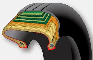
The direction of the plies used in construction of the tire, either bias or radial. Traditional aircraft tires are bias ply tires. The plies are wrapped to form the tire and give it strength. The angle of the plies in relation to the direction of rotation of the tire varies between 30° and 60°. In this manner, the plies have the bias of the fabric from which they are constructed facing the direction of rotation and across the tire. Hence, they are called bias tires. The result is flexibility as the sidewall can flex with the fabric plies laid on the bias
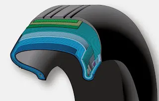
Some modern aircraft tires are radial tires. The plies in radial tires are laid at a 90° angle to the direction of rotation of the tire. This configuration puts the non-stretchable fiber of the plies perpendicular to the sidewall and direction of rotation. This creates strength in the tire allowing it to carry high loads with less deformation.
ROLLING RESISTANCE
Rolling resistance, sometimes called rolling friction or rolling drag, is the force resisting the motion when a body rolls on a surface. It is mainly caused by non-elastic effects; that is, not all the energy needed for deformation (or movement) of the wheel, roadbed, etc., is recovered when the pressure is removed
TYRE PRESSURE
Airplane wheel/tire assemblies are inflated to high pressures (many in excess of 200 psi). In addition, the pressure in the bottle or tire-servicing cart can be as high as 3,000 psi. As a result, when the high-pressure bottle is connected directly to the wheel without a regulator, the wheel is suddenly subjected to the high pressure, which can exceed the design limits for the wheel and the wheel tie bolts. Consequently, the wheel, the wheel tie bolts, or both experience an explosive fracture and become projectiles.
BRAKE FORCE WHEN LANDING
The most common type of brake used on aircraft is the disc brake. Disc brakes function by exploiting friction between rotating and stationary discs inside the brake.
The discs are mounted on a carrier assembly consisting of a torque tube, which resists and transmits brake torque to the landing gear structure. Sandwiched together between the carrier assembly housing and a backing plate, the discs are arranged in an alternating pattern of rotors and stators. Notch and groove geometry around the circumference of each rotor fits into corresponding geometry in the wheel, keying the rotors to the wheel so that they rotate with it.
In aeronautics, air brakes or speed brakes are a type of flight control surfaces used on an aircraft to increase drag or increase the angle of approach during landing. Air brakes differ from spoiler in that air brakes are designed to increase drag while making little change to lift, whereas spoiler reduce the lift to drag ratio and require a higher angle of attack to maintain lift, resulting in a higher stall speed
OBEJCTIVE 6: With necessary assumptions, calculate the force and power required to push / pull an aircraft by a towing vehicle.
let us Assume:
Weigth of the aircraft:575000kg
Rolling Resistance co-efficient of an aircraft=0.004
Weigth of the towing tractor=50000kg
Rolling Resistance co-efficient of Towing Vehicle=0.001
Rolling Resistance force of tow tractor=0.001*50000*9.81=0.49KN
Rolling Resistance Force of aircraft=0.004*575000*9.81=22.56KN
Total Rolling force=23.05KN
AIR DRAG FORCE:
Velocity of the aircraft while towing:8.33m/s
Density of Air medium=1.225
The frontal area of the Aircraft=20m^2
The coefficient of Drag of the Aircraft=0.026
Air drag force=0.5*rho*A*V^2*cd=0.022KN
The power required:
The avg speed of push/pull=5.5m/s
power required by the motor = Total force*Velocity=23.07*5.5
Power required by the motor=126.8KW
Assuming radius of the tyre=0.635m
Gear ratio=11
T=(Fte*r)/G
T=1.327KNm
The torque required to push/pullfor the above stated condition = 1.327KNm
OBJECTIVE 7: Design an electric powertrain with type of motor, it’s power rating, and energy requirement to fulfill aircraft towing application. Estimate the duty cycle range to control the aircraft speed from zero to highest. Make all required assumptions. Prepare a table of assumed parameters. Draw a block diagram of powertrain.
From the above calculation
Power required by the motor=126.8KW
The torque required to push/pullfor the above stated condition = 1.327KNm
If the motor is consider to be 95% efficient, then the motor torque= 1.327/0.95=1.39KNm
similarly power required by the motor considering all the efficiencies =126.8/(0.95*0.85)=156Kw
let us assume the towing opearation runs for 15mins(0.25 hrs)
Total Energy consumed = 156*0.25=39Kwh
A battery of higher capacity than this needs to be selected.Thus the storage of energy in battteries with high performance ultracapacitors are selected to fullfill the required power deliver
Motor selectrion :
Here BLDC motor tyoe that ha spower rating of 156Kw and with gear ratio and the transmission it should be able to deliver 1.39KNm torque instantaneously.