Project-1: Powertrain for aircraft in runways
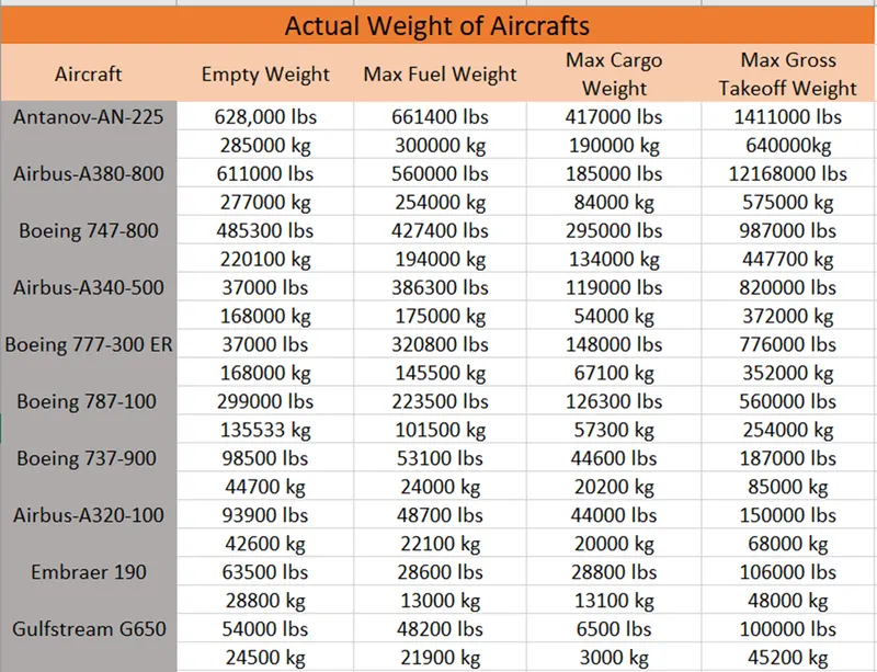
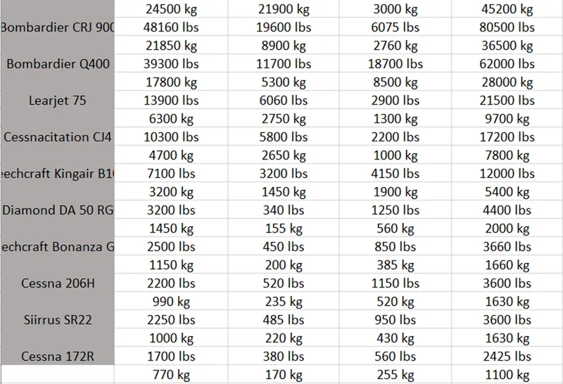
1. Search and list out the total weight of various types of aircrafts
Actual Weight of Various types of aircrafts
There are many factors that lead to efficient and safe operation of aircraft. Among these vital factors are proper weights and balance control.
The maximum allowable weight for an aircraft is determined by design considerations. The manufacturer provides the aircraft operator with the empty weight of the aircraft and the location of its empty weight centre of gravity (EWCG) at the time the certified aircraft leaves the factory.
However, the maximum operational weight may be less than the maximum allowable weight due to such considerations as high-density altitude or high-drag field conditions caused by wet grass or water on the runway. The maximum operational weight may also be limited by the departure or arrival airport's runway length.
Aircraft Empty Weight (AEW)
This is sometimes referred to as OEW - Operating Empty Weight and it is the weight of the aircraft with all its equipment on board but no fuel, no passengers or no cargo.
Think of this like the aircraft has just come out of the factory and is sitting waiting to be fuelled up for delivery to the customer.
Aircraft Maximum Gross Take-off Weight (MGTW)
This is the maximum permissible weight the aircraft can weigh as it lifts off the ground at take-off. This includes the aircraft's empty weight, the fuel, the crew, the passengers, and all the cargo.
This weight limit is set by the manufacturer and is gospel. Many aircraft accidents have been caused by an aircraft being overweight and the pilot/s have not had enough power or manoeuvrability to prevent the accident.
Aircraft Useful Load
This is the weight that a pilot can place in the aircraft. Take the MGTW figure and subtract the AEW and this is the total useful load that can be placed into the aircraft. This is the fuel, crew, passengers, and cargo. The bigger the load, the more useful the aircraft can be to its customers.
2. Is there any difference between ground speed and air speed?
Ground Speed
Ground speed is the speed that determines how fast an aircraft will go to its destination. Its is the aircrafts speed relative to the ground. One thing that should be noted here is that it is horizontal rather than the vertical speed- an aircraft climbing completely vertically would have a ground speed of zero.
Air Speed
Air speed is the speed at which the aircraft is moving relative to the air it is flying. It is also the speed at which the air is flowing around the aircraft’s wings. In other words, airspeed is the speed that determines whether there is enough airflow around an aircraft to make it fly.
Winds Effect on Ground Speed
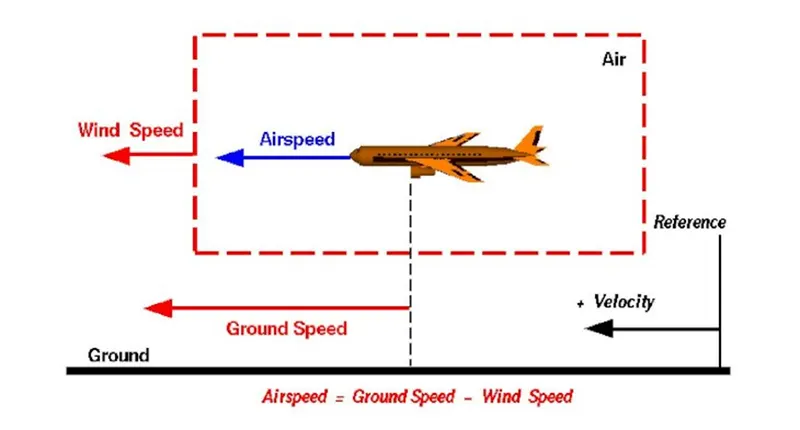
The relation between airspeed and ground speed is simple. Ground speed is simply the sum of airspeed and the wind speed.
If the aircraft is flying in the same direction as the wind is blowing, the aircraft experiences tailwind, and its ground speed is higher than its airspeed. On the other hand, if the wind is blowing against the direction the aircraft is travelling in, the aircraft experiences headwind, and its ground speed is lower than its airspeed.
Ground Speed = Air Speed + Wind Speed
Air Speed = Ground Speed – Wind Speed
3. Why it is not recommended to use aircraft engine power to move it on the ground at airport?
Airplanes use their jet engines for taxing just like for flying. And they have no additional engines to power the wheels. Unlike the other ground-based vehicles, there is no linkage or connection between the engine(s) and the tyre(s). The engines produce thrust in the normal way by sucking in some air from the front and accelerating it backwards either through a jet engine or using a propeller. As a result, the whole aircraft moves forward.
By twisting the propeller's blades, it is possible to have them suck air from behind and accelerate it forward. That way, the aircraft can move backwards. But this facility is highly risky and it is only used to reduce the speed of the aircraft after landing.
Production of such 'reverse thrust ‘for moving backwards is not possible in turbine engines. In those, there would be some panels that come over the exhaust portion of the engine which deflect the air forward and if the engine power is increased, the engine would produce reverse thrust. At very slow speeds, if such reverse thrust is 'demanded' by the pilot, there is a possibility that the exhaust gases go into the inlet. Since the gas coming out of the exhaust contains very little oxygen, further combustion is not possible with it and the engine might just switch off. Therefore, the aircraft model's operating procedures would demand that the reverse thrust is cancelled when the aircraft is below a certain speed.
4. How an aircraft is pushed to runway when its ready to take off?
Tug vehicles or Towing tractors are generally used to push back the plane away from the terminal prior to take-off. These are specialized vehicles with high torque and heavy mass.
The reason for the use of tugs is that the alternative (i.e., pushback using the jet-engine's thrust-reverser) is a highly fuel-consuming and noisy process. It is also potentially hazardous for personnel working near the plane. Once the plane is tugged away to a safe distance from the terminal, the plane begins using its own engine power for the rest of the taxing process.
Procedure
Closer to the departure, an aircraft tug will park right in front of the nose wheel. The tug might be directly attached to the planes nose gear with a tow bar, or could be a wheel-lift tug. These tugs cradle the nose gear, then lift it up before moving the plane. That gives the tug driver control over the plane’s direction during pushback.
New taxi technologies are appearing, like pilot-controlled tugs, and electric motors mounted to the planes landing gear. Both promise to save fuel, and reduce airport noise.
5. Learn about take-off power, tyre design, rolling resistance, tyre pressure, back forces when landing?
Take-Off Power: Take-off is the phase of flight in which an aerospace vehicle leaves the ground and becomes airborne. For aircraft that take off horizontally, this usually involves starting with a transition from moving along the ground on a runway. For light aircraft, usually full power is used during take-off. Large transport category aircraft may use a reduced power for take-off, where less than full power is applied in order to prolong engine life, reduce maintenance costs and reduce noise emissions. The aircraft is permitted to accelerate to rotation speed. The term rotation is used because the aircraft pivots around the axis of its main landing gear while still on the ground, usually because of gentle manipulation of the flight controls to make or facilitate this change in aircraft attitude and once proper air displacement occurs under or over the wings, an aircraft will lift off on its own.
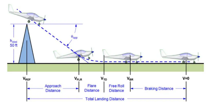
Generally, the T-O phase is split into the segments shown in the figure below. The ground roll is the distance from brake release to the initiation of the rotation, when the pilot pulls the control wheel (or stick or yoke) backward in order to raise the nose of the aircraft. This maneuverer is required to increase the area of attack of the airplane to help it become airborne. The aircraft typically remains in this attitude for some 1-3 seconds, depending on aircraft size, before the tires lose contact with the ground. This segment is called the rotation. The rotation phase concludes as the aircraft lifts off the ground and begins the transition and subsequent climb phase.
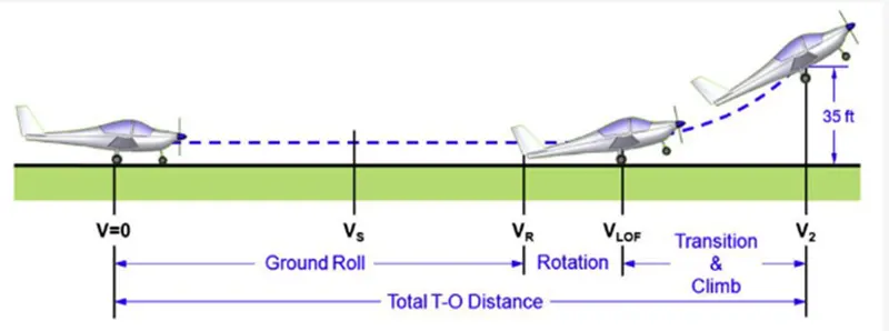
Here V is the instantaneous airspeed of the aircraft, V is the ground run speed, V is the lift off for rotation speed, V is the climb speed and V is the stalling speed in the T-O configuration. This means that if the airplane features high-lift devices, V refers to the stalling speed with flaps deployed. The important point is that the airplane must accelerate from standstill to a given airspeed, called the lift-off speed, before it can, well, lift off. Generally, the take of speed or the climb speed of the aircraft (V2) is calculated as,
V₂ = 1.2Vs
Where the stalling speed at the Take-Off configuration is given as
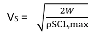
In the above equation, W is the gross weight of the aircraft, p' is the free stream density of air. 'S' is the wing area of the aircraft and CLmax is the maximum lift coefficient.
The take-off speed required varies with aircraft weight and aircraft configuration; the heavier the weight, the greater the speed needed. Typical take-off air speeds for jetliners are in the range of 240-285 km/h, light aircraft take off at around 100 km/h and ultra-lights have even lower take-off speeds
Tyre Design - An aircraft must withstand a wide range of operational conditions. When on
the ground, it must support the weight of the aircraft, during taxied it must provide cushioned ride. At take off the tire structure must be able endure forces generated at higher angular velocities. Landing requires the tire to absorb impact shocks. These extreme demands require a tire which is highly engineered and precisely manufactured. For these tires are made of various rubber, fabric and steed material. To meet the aircraft demands tire are manufactured in two distinct categories Bias tire and radial tire.
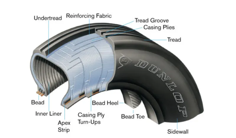
Bias Tyre construction - these types of tires consist casing plies which is running diagonally
at approximate right angle to one another. The number of plies and the angles at which they are laid decide strength and load capacity.
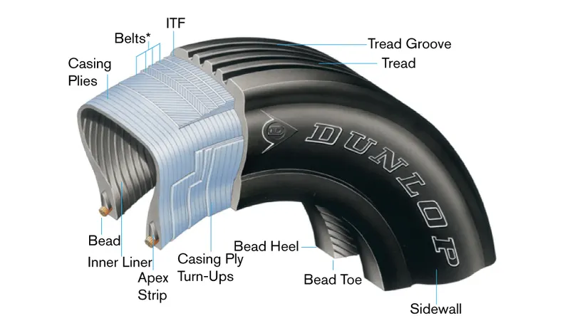
Radial Tyre construction - these are the most modern design of aircraft tyres.in radial tires each carcass ply is laid at right angle. The radial tire offers more landings per thread and lighter weight than a bias tire.
Tyre Pressure: Aircraft tires generally operate at high pressures, up to 200 psi (14 bar; 1,400
kPa) for airliners, and even higher for business jets. Tests of airliner aircraft tires have shown that they are able to sustain pressures of maximum 800 psi (55 bar: 5,500 kPa) before bursting. During the tests the tires have to be filled with water, to prevent the test room being blown apart by the energy that would be released by a gas when the tire bursts. Aircraft tires are usually inflated with nitrogen to minimize expansion and contraction from extreme changes in ambient temperature and pressure experienced during flight. Dry nitrogen expands at the same rate as other dry atmospheric gases (normal air is about 80% nitrogen), but common compressed air sources may contain moisture, which increases the expansion rate with temperature. The requirement that an inert gas, such as nitrogen, be used instead of air for inflation of tires on certain transport category airplanes was prompted by at least three cases in which the oxygen in air-filled tires had combined with volatile gases given off by a severely overheated tire and exploded upon reaching auto ignition temperature. The use of an inert gas for tire inflation eliminates the possibility of tire explosion.
Rolling resistance - when a tire rolls on the road, mechanical energy is converted to heat as a result of phenomenon referred to as rolling resistance. The term rolling resistance is often mistaken as a measure of the force opposing tire rotation, when instead is actually a measure of rolling energy loss. in another terms we can say rolling resistance is the effort required to keep a given tire rolling. Its magnitude depends on the tire used, roughness of road, inflation pressure, load and speed. Generally rolling resistance is given by following formula
Frr = цrr * m* g
цrr = Rolling Resistance Coefficient
m = mass of the vehicle (kg) (Pay load + Kerb load)
g = acceleration due to gravity (m/s2) = 9.81 m/s2
Brake forces when landing: The forces acting on an aircraft during landing are the same as those during any other phase of flight: thrust, drag, lift, and weight. During the approach phase, if the aircraft descends at a constant rate and speed (ie acceleration in any axis is zero) then all the forces must be balanced (thrust = drag, lift = weight).
During the flare (the instant the airplane is pulled up slightly, usually about 2 to 5 feet above the runway) the angle of attack is increased. This in turn causes an increase in lift and drag. Since no power is added (thrust is still constant) the airplane will slow down. The decreasing airspeed will cause the lift to decrease.
This transition and changes in force balance happen simultaneously and (in a good landing) smoothly. The increase in lift is just enough to slow the rate of descent (from perhaps 500 ft/min from the approach phase to 50 to 100 ft/min during flare). This leads to a soft touch down at a decreasing airspeed.
If the airplane comes in too fast, the pull up during the flare will cause much more lift than needed for a good flare causing the airplane to stop descending and actually gain altitude (ie aka "ballooning"). If the airplane is coming in too slow the pull up will result in some lift, but the reduction in airspeed from an already slow airplane could lead to a partial or full stall. This happens due to an excessive angle of attack (pulling up at low airspeeds causes this). As the airplane stalls it will rapidly loose lift, resulting in a hard (potentially dangerous) landing.
6. A) With necessary assumptions, calculate the force and power required to push/pull an aircraft by a towing vehicle.
The force to move an airplane on an absolute flat runway with no wind at constant low speed is equal to the rolling resistance between the plane and the tarmac.
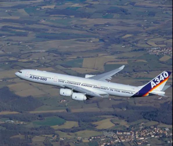
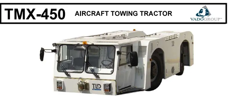
Here I considered aircraft Airbus-A340-500 and the towing vehicle to tow the aircraft as TMX-450
Airbus-A340-500
Description
The four-engine, twin-aisle wide-body jetliner’s range of up to 9,000 nautical miles allows the A340-500 to operate some of the world’s longest non-stop routes, while its optimised 222-inch fuselage cross-section gives airlines the cabin versatility to match market requirements.
Specifications
Wing Area = 439.4m2
Max gross Take-off Weight =372000 kg
Speed = 915 km/h
Rolling resistance coefficient = 0.009
Air Drag coefficient = 0.025
TMX-450
Description
The TMX-450 Aircraft Towing Tractor, with a maximum driveline capability of 32,000daN (70,500 lbs) is designed to perform push back and towing operations on medium and wide body aircraft (like the B767, B777, B747, A300/A310, A330/A340 up to 500 /600)
Its ergonomic design provides maximum driver comfort and increased visibility. TLD's high standards of build and component quality make the TMX-450 a durable and reliable tractor.
Specifications
Weight of the TMX-450-45 Tractor = 45000 kg
Transmission: ZF Powershift transmission, 6WG210 with inter axle differential, 6 speed forward and 3 reverse
Max speed forward/reverse = 25kph (15.5 mph)
Tyres = 385/95 R 25
Fuel Tank Capacity = 300 litres
Hydraulic Tank Capacity = 115 litres
Length = 7180 mm
Width = 2980 mm
Height = 1650 mm
Outside turning radius = 6400 mm
The rolling resistance for the airplane can be calculated as
Rolling Resistance Force (Frr) for Airplane
Frr = цrr * m* g
цrr = Rolling Resistance Coefficient
m = mass of the vehicle (kg) (Pay load + Kerb load)
g = acceleration due to gravity (m/s2) = 9.81 m/s2
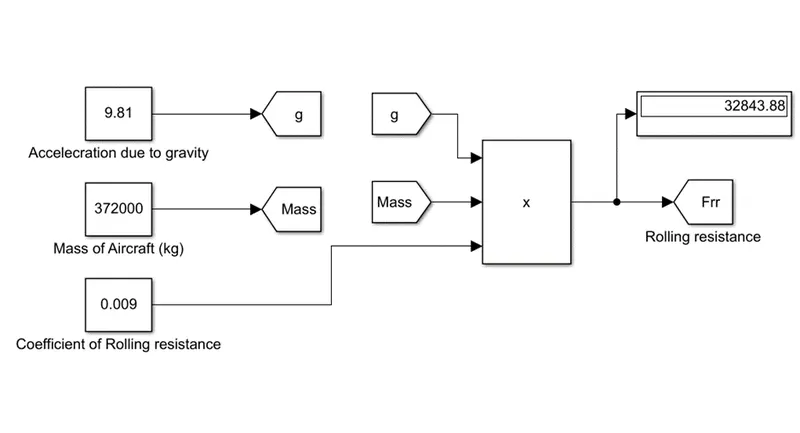
= 0.009 * 372000 * 9.81
=32843.88 N - - - - - - - - - (1)
This force can be delivered by a pulling truck or -as occasionally seen by a number of pulling people. Enough weight for the pullers is required to create friction forces against the tarmac that equals the plane rolling resistance.
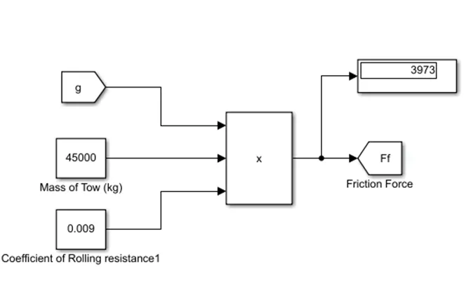
Rolling Resistance Force (Ff) for Towing vehicle
The friction force for the Towing Vehicle can be calculated as
Ff = цf * mf* g
= 0.009*45000*9.81
=3973.05N - - - - - - - (2)
Air Drag Force (Fad)
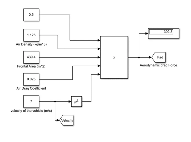
The Drag force acting on the tow will be the drag force F d exerted on a body travelling through a fluid, it is given by the equation
Fad = 1/2 (ρ* A* Cd * V2)
ρ = Density of Air (Kg/m3)
A = Frontal Area of vehicle (m2)
Cd = Drag Coefficient
V = Velocity (m/s)
considering mass of the velocity of the pulling truck as 25 kmph (7 m/s) drag coefficient as 0.025 density of air (ρ) = 1.125 Kg/m3
Here we consider wing area of the aircraft as Frontal Area = 439.4m2
Fad = 1/2 (ρ* A* Cd * V2)
= 1/2 (1.125*439.4*0.025 *72)
=302.77N - - - - - - - - (3)
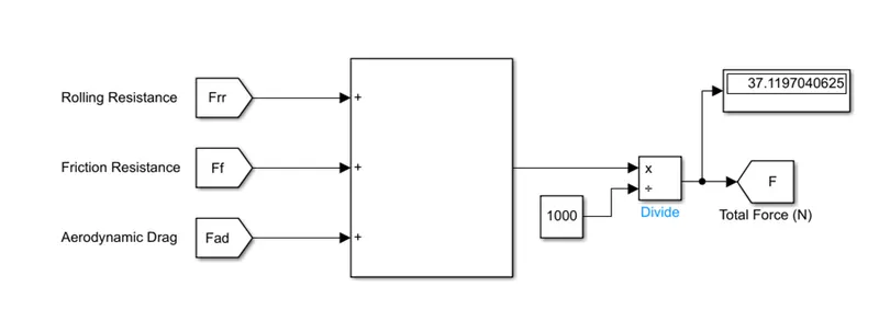
The Total pulling force = (1) + (2) + (3)
= 32843.88+3973.05+302.77 = 37119.70N
=37.11970 KN
Power = Force * velocity
= 37.11970 * 7
= 259.83 kW
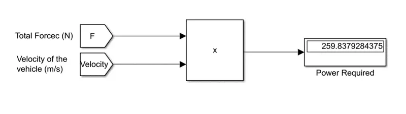
The minimum power required by the following vehicle is 259.83 kW
6 B)Develop the model for the calculated force and power using Simulink.
Model:
Model for Rolling Resistance Force for Aircraft
Model for Rolling Resistance Force for Towing Vehicle
Model for Aerodynamic Drag Force
Model for Total Force Calculation
Model for Power required Calculation
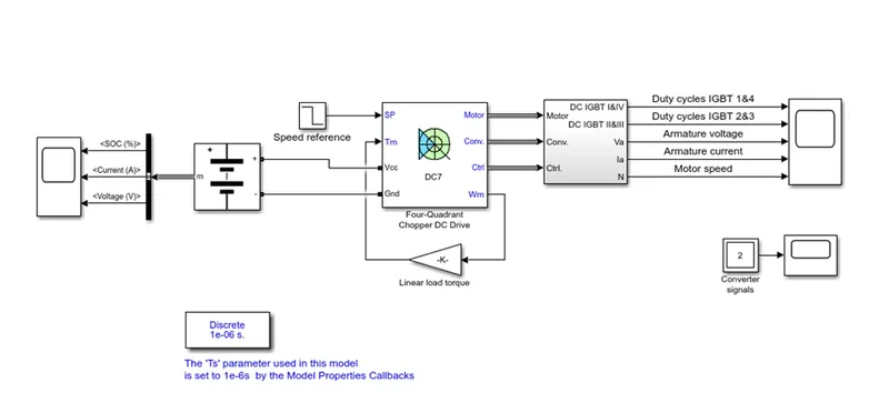
7.A) Design an electric powertrain with type of motor, its power rating, and energy requirement to fulfil aircraft towing application in Simulink.
Estimate the duty cycle range to control the aircraft speed from zero to highest. Make all required assumptions. Prepare a table of assumed parameters. Draw a block diagram of powertrain.
(Hint: DC7 Block)
Parameters
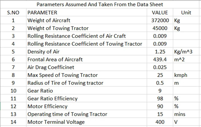
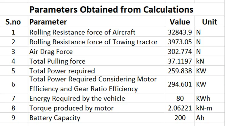
From the above calculation we get to know that power required by the towing vehicle to push/pull the aircraft is 259.83 kW
Here I considered the motor efficiency as 90% and the gear ratio efficiency as 98%
The total power required = 259.83/ (0.9*0.98) = 294.59 kW
From this we can now calculate the energy required by the vehicle or supplied by the battery
Considering towing can be done in 15 minutes so energy required = power required * time
Energy = 294.59kW *0.25hr = 73.64 kWh
From the Tire data we have calculated the radius of tire as 0.5m and assumed the gear ratio as 9
Torque = Force * Radius of Tire / Gear Ratio
= 37.1190*0.5/9
=2.06KN-m
Therefore, the battery must be able to store 73.64 kWh and should be able to deliver this energy throughout the run time in order for the motor to produce 2.06KN-m of torque instantaneously.
Here i considered the motor of 300kW (400 HP) that can deliver the continuous power of 300kW with the terminal voltage 400V
The battery energy was taken as 80kWh from this we can calculate the Battery Capacity (Ampere hour rating) of the battery
= (80*1000)/400 = 200Ah
Model:
Result:
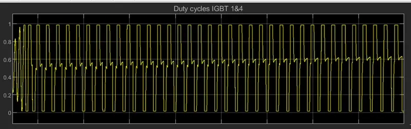
Duty Cycle of IGBT 1 & 4
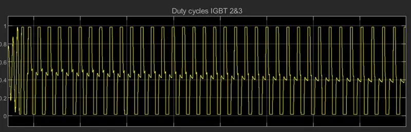
Duty Cycle of IGBT 2 & 3
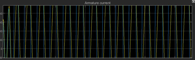
Armature Current
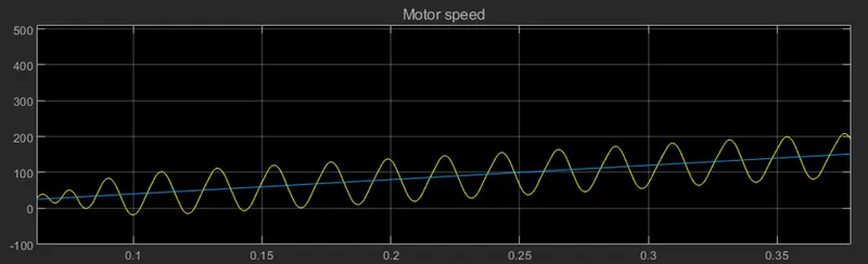
Motor Speed
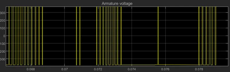
Armature Voltage
7. B) Design the parameters in the excel sheet
Parameters Assumed
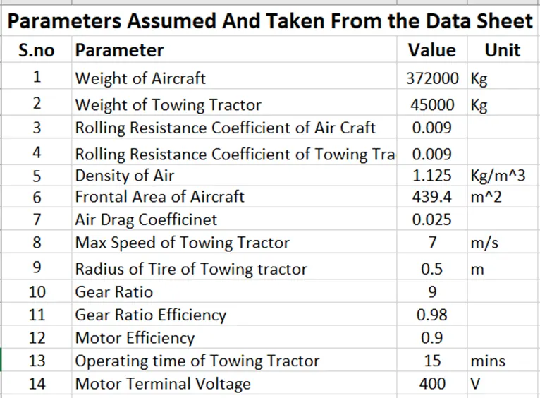
Designing the Required Parameters
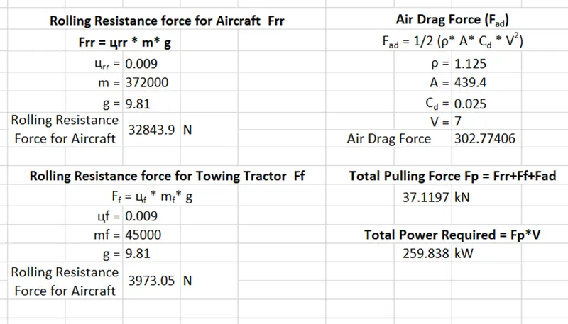
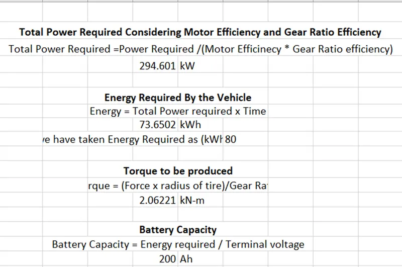
Parameters Obtained from Calculations