Project-1: Powertrain for aircraft in runways
AIM:
Part A:
1. Search and list out the total weight of various types of aircrafts.
2. Is there any difference between ground speed and air speed?
3. Why is it not recommended to use aircraft engine power to move it on the ground at Airport?
4. How an aircraft is pushed to runway when its ready to take off?
5. Learn about take off power, tyre design, rolling resistance, tyre pressure, brake forces when landing.
Part B:
6. A. With necessary assumptions, calculate the force and power required to push / pull an aircraft by a towing vehicle.
B. Develop the model for the calculated force and power using Simulink.
7. A. Design an electric powertrain with type of motor, it’s power rating, and energy requirement to fulfill aircraft towing application in Simulink. Estimate the duty cycle range to control the aircraft speed from zero to highest. Make all required assumptions. Prepare a table of assumed parameters. Draw a block diagram of powertrain.
(Hint :DC7 Block)
B. Also, Design the parameters in excel sheet.
#1. Search and list out the total weight of various types of aircrafts.
Weight is a major factor in airplane construction and operation, and it demands respect from all pilots and particular diligence by all maintenance personnel. Excessive weight reduces the efficiency of an aircraft and the available safety margin if an emergency condition should arise. The total weight is the maximum take-off weight. It is the maximum mass at which the aircraft is certified for take-off due to structural or other limits.
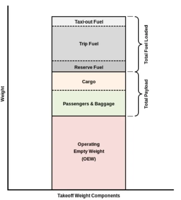
MTOW = Maximum take-off weight, MLW = Maximum landing weight, TOR = Take-off run, LR Landing run
Maximum Takeoff Weight:
The maximum weight limits for an aircraft to begin its takeo roll is called the max takeoff weight.
Maximum Landing Weight:
The maximum landing weight is, as you might imagine, the maximum aircraft weight limit approved for an aircraft to land. Landing weight can cause structural damage.
Type MTOW [kg]
Antonov An- 225640,000
Scaled Composites Model 351 Stratolaunch589,670
Airbus A380-800575,000
Boeing 747-8F447,700
Boeing 747-8443,613
Boeing 747-400ER412,770
Douglas DC-8-32140,000
Tupolev Tu-154M104,000
Bombardier Q40028,000
ATR 42-50018,600
BAe Jetstream 4110,890
Learjet 759,752
Cessna Citation CJ47,761
MTOW[kg]: Maximum Take off weight in kg
#2. Is there any difference between ground speed and air speed?
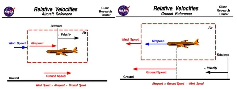
Ground speed
Ground speed is the horizontal speed of an aircraft relative to the ground. An aircraft heading vertically would have a ground speed of zero.
Ground speed can be determined by the vector sum of the aircraft's true airspeed and the current wind speed and direction; a headwind subtracts from the ground speed, while a tailwind adds to it. Winds at other angles to the heading will have components of either headwind or tailwind as well as a crosswind component.
Wind Speed
For a reference point picked on the ground, the air moves relative to the reference point at the wind speed. A positive velocity is defined to be in the direction of the aircraft's motion. We are neglecting cross winds, which occur perpendicular to the flight path but parallel to the ground, and updrafts and downdrafts, which occur perpendicular to the ground.
Airspeed
The important quantity in the generation of lift is the relative velocity between the object and the air, which is called the airspeed. Airspeed cannot be directly measured from a ground position, but must be computed from the ground speed and the wind speed. Airspeed is the vector difference between the ground speed and the wind speed.
Airspeed Ground Speed - Wind Speed
- The aircraft usually operates on land as well as in air and so we need to study their speed differences in-ground and in air
- The ground speed and the airspeed usually change based on the wind component.
- If we consider that there is no wind component then, ground speed = airspeed
- If the wind is blowing in the tail direction of the aircraft then, (airspeed > ground speed) so, airspeed = ground speed+ wind component.
- If the wind is blowing in the head direction of the aircraft then, (airspeed < ground speed)so, airspeed ground speed - wind component.
- Also, gravity plays a major role in increasing the aircraft's speed while it is descending.
- Here wind speed is the vector difference between ground and airspeed. On a particular day, the wind speed may be zero and it is equal to the ground speed.
- If the measured airspeed is greater than the observed ground speed the wind speed becomes positive.
For Visualisation purporse by NASA:
https://www.grc.nasa.gov/www/k-12/airplane/Animation/airrel/anrelg.html
#3. Why is it not recommended to use aircraft engine power to move it on the ground at Airport?
Aircraft can move using their own engine power all the time on the airport apron and taxiways under their own power to go towards runways and after landing taxi to their assigned gate. But the thrust produced resulting jet blast might cause damage to the terminal building or equipment. Engines close to the ground may also blow sand and debris forward and then suck them into the engine, causing damage to the engine. A pushback is therefore the preferred method to move the aircraft away from the gate. And also it can reduce the cost for fuel. Taxiing can save money.
- Effectively a loss of control can happen, especially during high power engine running. Damage can occur to the aircraft itself, other aircraft nearby or to airsidestructures.
- There is a risk of injury to ground support personnel who may be in relatively close proximity to the aircraft.
- It is easier for truck driver to see the surroundings better than the pilot sitting in the cockpit with limited window. The pushback driver knows the airport better than the pilot.
- It also saves fuel virgin Atlantic hadproposed a new system in which pushback truck will move the aircraft all the way to runway to save fuel and reduce impact of environment.
- The plane engines are very loud. When more than one plane will add up their sound, than it will not be pleasent for passangers and others near airport.
#4. How an aircraft is pushed to runway when its ready to take off?
Taxiing
Taxiing is the movement of an aircraft on the ground, under its own power, in contrast to towing or push-back where the aircraft is moved by a tug. The aircraft usually moves on wheels, but the term also includes aircraft with skis or floats . An airplane uses taxiways to taxi from one place on an airport to another; for example, when moving from a hangar to the runway.
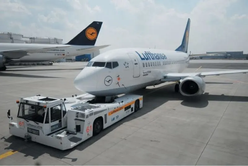
Towing:
Movement of large aircraft about the airport, flight line, and hangar is usually accomplished by towing with a tow tractor. In the case of small aircraft, some moving is accomplished by hand pushing on the correct areas of the aircraft. Aircraft may also be taxied about the flight line but usually only by certain qualified personnel.
Towing aircraft can be a hazardous operation, causing damage to the aircraft and injury to personnel, if done recklessly or carelessly. This article outline the general procedure for towing aircraft. However, specific instructions for each model of aircraft are detailed in the manufacturer's maintenance instructions and are to be followed in all instances.
#5. Learn about take off power, tyre design, rolling resistance, tyre pressure, brake forces when landing.
Take off power:
Take off power can be predicted using a simple measure of the acceleration of the aircraft along the runway based on force equilibrium.
The forces involved will be.
T is Thrust of propulsion system pushing aircraft along the runway.
D is Aerodynamic Drag of vehicle resisting the aircraft motion.
F is Rolling resistance friction due to the contact of wheels or skids on the ground.
During the take-off run, the imbalance in these forces will produce an acceleration along the runway.
m*(dv/dt)=T-D-F
where, dv/dt is the acceleration along the runway and m is the mass of the vehicle.
The procedure for take-off will be that the vehicle will accelerate until it reaches a safe initial flying speed. The pilot can then rotate the vehicle to an attitude to produce a climb lift and it will ascend from the ground. The determination of this safe flying speed or rotation speed. V, is a critical factor in determining take-off performance. Take-off rules vary slightly depending on the aircraft category.
For Small commuter aircraft
V= 1.1*VSTALL
or
V=1.05*V Control
VSTALL≡W0.5ClmaxρS
where S-Runway length
Take Off power = force*displacement
(m⋅dvdt)⋅2⋅S1⇒(T-D-F).S1
Tyre Design:
Designing aircraft tires is a very intense undertaking The tyre is designed to withstand heavy loads while landing, take off, taxing, and parking. The number of wheels required for aircraft increases with the weight of the aircraft, as the weight of the aeroplane needs to be distributed more evenly. Aircraft tyre generates more heat during landing Aircraft drags the wheel until they match the rotational velocity of wheels. Due to this heat generates. Aircraft's tread pattern is designed to facilitate stability in high crosswind conditions, to channel water away to prevent hydroplaning and for braking effect.
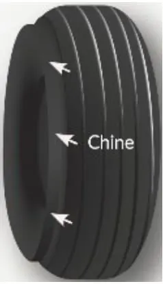
Construction of tyre:
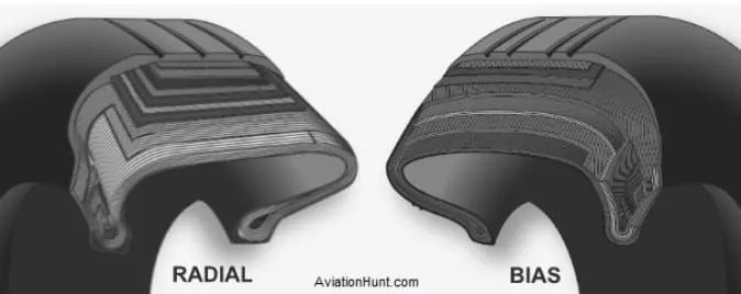
Radial Tyre: It has fibre strands of the ply fabric oriented at 90° to the direction of rotation and the tyre sidewall. This restricts flexibility bidirectional and the flexibility of the sidewall while it strengthens the tyre to carry heavy loads. Due to their unique construction most radial tyres are resistant to penetration ad cuts. Due to stiffer tread they distribute weight evenly. Thus provide greater traction. Radial tyres have an advantage in term of reducing the heat better.
Bias-ply Tyre: It has the fabric bias oriented with and across the direction of rotation and the sidewall. Since fabric can stretchon the bias, the tyre is flexible and can absorb loads. Tyre strength is obtained by adding plies. It is cut resistant is sidewall area. These tyres do not offer as much smoothness in terms of riding quality.
Rolling Resistance:
Rolling resistance is the force resisting the motion when a body (such as ball, tyre or wheel) rolls on a surface. Rolling resistance can be seen in the aircraft when the aircraft takes-off from the runway & while landing at the runway with the help of their wheels.
Rolling resistance can be expressed as
Frr=μrr⋅m⋅g
(N).
Where,
Frr
is the Rolli resistance(N)
μrr
is coefficient of rolling resistance.
m is mass (kg)
g is acceleration due to gravity = 9.81m/s^2
Tyre pressure:
Aircraft tyres operate at such high extremes of pressure, load, and speed, their care and service is critically important. The most important action an operator can take to prevent tyre-related events is to maintain proper tire inflation pressure. Failure to keep aircraft tires properly inflated can lead to very serious consequences. One relatively easy way to help avoid those consequences is to check tire pressures regularly and service them as necessary. Following these three actions is a good way to make sure you get the most value out of your tires and contribute to the safe operation of your aircraft.
Aircraft tires are usually inflated with nitrogen to minimize expansion and contraction from extreme changes in ambient temperature and pressure experienced during flight. Dry nitrogen expands at the same rate as other dry atmospheric gases (normal air is about 80% nitrogen). but common compressed air sources may contain moisture, which increases the expansion rate with temperature.
Also, the use of an inert gas for tire inflation eliminates the possibility of tire explosion.
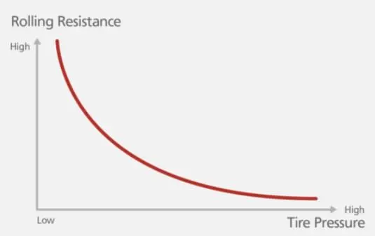
Relation to Rolling Resistance and Tire Pressure:
Rolling resistance and Tire pressure are inversly proportional.
Braking Forces During Landing:
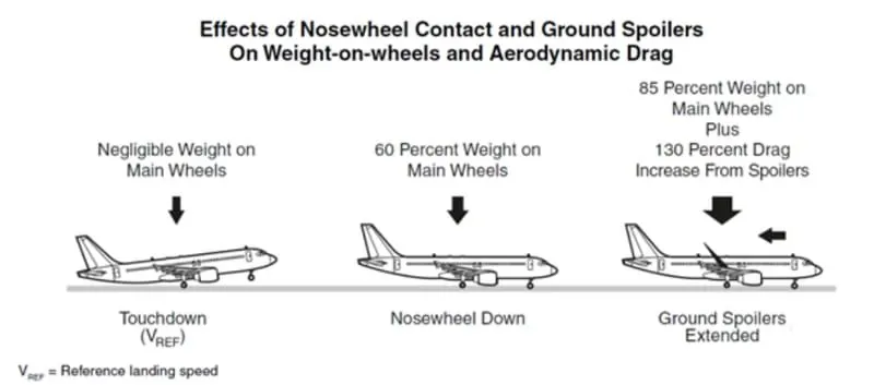
Following braking devices are used to decelerate the aircraft -
1. Spoilers.
2. Wheel Brakes (Including Anti-Skid systems & Auto-Brake systems).
3. Reverse Thrust
Spoilers:
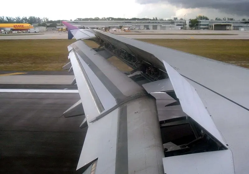
The mechanical deflection of parts of the wing upper surface by increasing aerodynamic drag on the moving aircraft. This can be achieved by raising upper wing surface panels called ground spoilers or by operation of a tail cone 'clamshell' type air brake and also by increasing the effective downward load on the landing gear and thereby increasing the efficiency of wheel braking
Wheel Brakes:
To be effective, braking action at any speed depends upon sufficient friction existing between the tires and the runway surface achieved through freely rotating wheels.
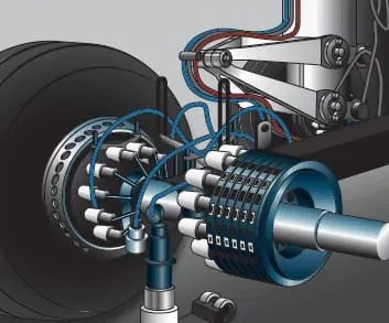
Anti skid system:
When landing on slippery runways, there's a chance that the wheels may start to skid as the brakes are applied. To stop this from happening and to maintain maximum effective braking, each wheel has anti-skid protection.
Using a variety of sources to determine the aircraft speed, the brake units know how fast the wheels should be spinning. If that speed drops significantly, it's because the current brake pressure on that wheel is too great and the wheel is just skidding over the surface.
In this situation, the anti-skid system automatically reduces the braking on that wheel to a point where the skid stops before reapplying the pressure.
Reverse Thrust:
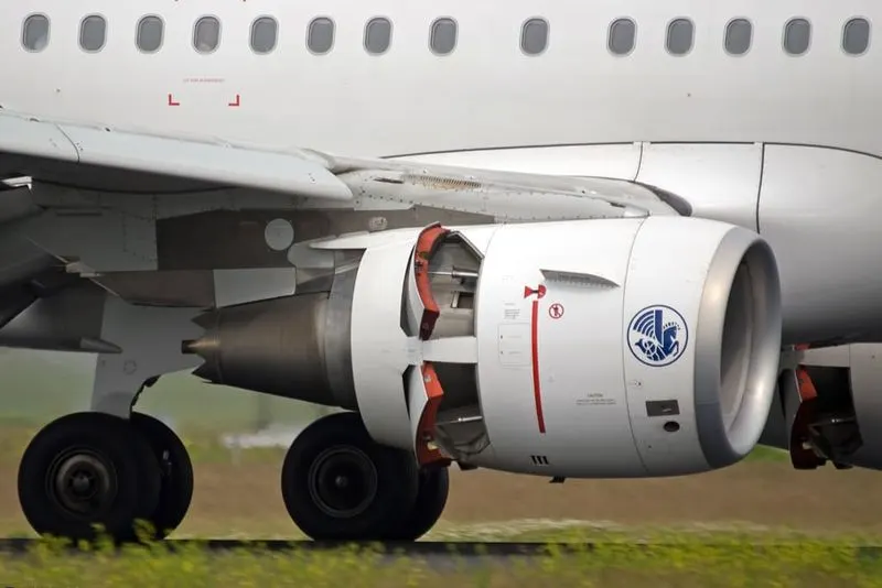
Thrust reversers provide a deceleration force that is independent of runway condition. Thrust reverser efficiency is higher at high airspeed therefore. Treversers must be selected as early as possible after touchdown.
Thrust reversers should be returned after reverse idle at low airspeed to prevent engine stall or foreign object damage.
#6. A. With necessary assumptions, calculate the force and power required to push / pull an aircraft by a towing vehicle.
B. Develop the model for the calculated force and power using Simulink.
A. With necessary assumptions, calculate the force and power required to push / pull an aircraft by a towing vehicle.
Considering:
Total mass of ther aircraft (including payload) for airbus a380 = 575,000kg.
Mass of the push back: 1000kg (assumed)
Rolling Resistance (Frr):
Coefficient of rolling resistance (Crr) = 0.002 (on tarmac)
Rolling resistance force is given by
Frr=Crr⋅m⋅g
For the aircraft:
Frr=0.002⋅575000⋅9.81⇒Frr=11281.5N⇒Frr=11.2815kN
For the Towing Vehicle:
Frrt=0.002⋅1000⋅9.81⇒Frrt=19.62N
As the towing vehicle resistance is so less compared to the Aircraft because this is a heavy aircraft these can be neglected
Aerodynamic resistnace (Far):
Drag coeffcient(Cd): 0.025
Air Density (ρρ) = 1.125kg/m^3
Frontal Area (A): 150m^2.
Velocity (v) = 14.5kmph or 4m/s
Far=12⋅Cd⋅ρ⋅A⋅v2
Far=12⋅0.025⋅1.125⋅150⋅42⇒33.75N
As the vehicle and Plane is moving at very low speed Aerodynamic resistance can be neglected
Hill Climb Resistnace:
Runways are constructed flat so Gradient resistance/ hill climb force is neglected.
Total Resistance:
Ft=11.2815kN
Power Required:
P=Ft⋅v⇒P=11.2815⋅4⇒45.26kW
The min power required by the tow vehicle is 45.26kW to taxi a heavy air craft at 4m/s.
B. Develop the model for the calculated force and power using Simulink.
Simulink Model:
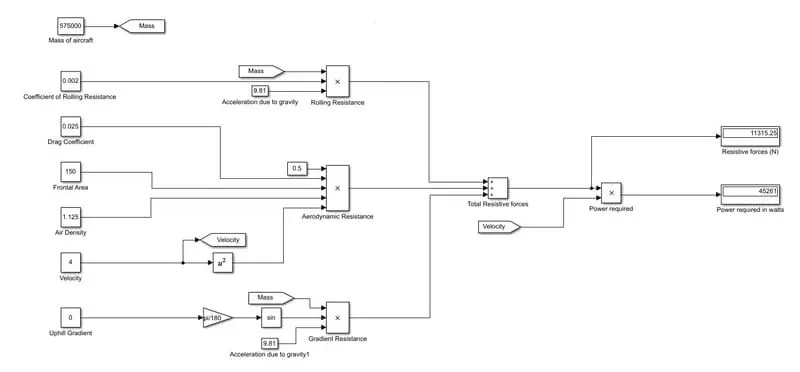
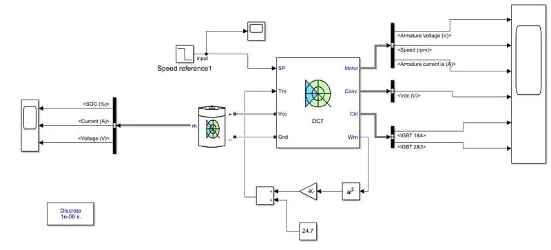
- constant blocks are used to feed the parameters such as mass, coefficients and other parameters
- using product block the resistive forces are calculated.
- using sum block, total resistive forces can be calculated.
- the outputs are visualised using display blocks.
#7. A. Design an electric powertrain with type of motor, it’s power rating, and energy requirement to fulfill aircraft towing application in Simulink. Estimate the duty cycle range to control the aircraft speed from zero to highest. Make all required assumptions. Prepare a table of assumed parameters. Draw a block diagram of powertrain.
B. Also, Design the parameters in excel sheet.
A. Design an electric powertrain with type of motor, it’s power rating, and energy requirement to fulfill aircraft towing application in Simulink. Estimate the duty cycle range to control the aircraft speed from zero to highest. Make all required assumptions. Prepare a table of assumed parameters. Draw a block diagram of powertrain.
Estimation of Duty Cycle:
Based on the calculation done in study 6
The Power Required for towing of the aircraft is 45.26kW.
Motor Considred for the drive train is REB 90
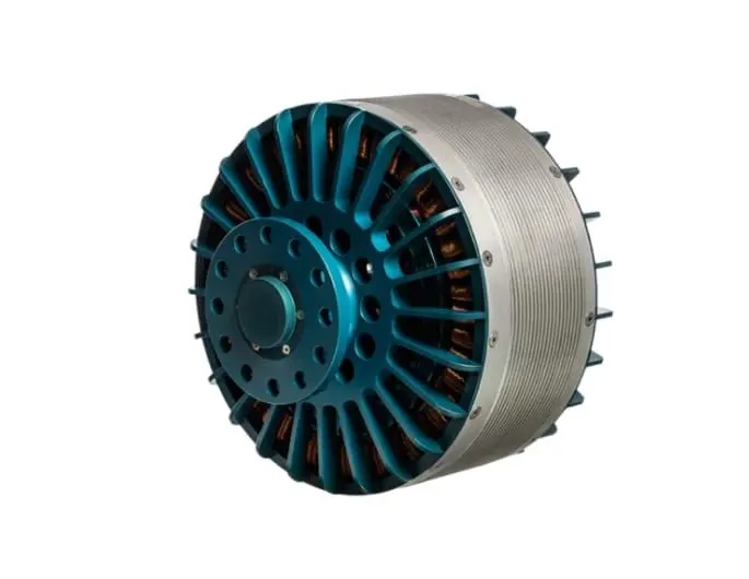
Technical Data:
TypeVoltage
Continuous / Peak power
Working rotation
Max torque
Weight
Cooling
REB 90
400–800 V
60–70 kW / 80 kW
1 500–4 000 rpm
300 Nm
22 000 g
Air / Hybrid (air + fluid)
Considering 60kW as continuous power, so the voltage will be 400V
Battery power is considred to be 550v
Duty cycle is given by
Vo/Vb
where Vo is motor required voltage
Vb is battery voltage.
d=400/550⇒0.7272
As there will be losses due to the resistance of FET and Inductance.
Correction factor is considred to be 90%
As there is 10% loss, the voltafge demanded by the motor should be 10% more than required
d=0.7272⋅(1+0.1)=0.799≈0.8
so the voltage demand should be around 440V from the battery.
Assumed Parameters
Mass of aircraft
575000kg
Mass of the push back truck
1000kg
Coefficient of Rolling Resistance
0.002
Drag Coefficient
0.025
Air density
1.125kg/m^3
Frontal Area
150m^2
Velocity
4m/s
Uphill gradient
0deg
Battery Voltage
550V
Correction Factor
0.8
Block Diagram:
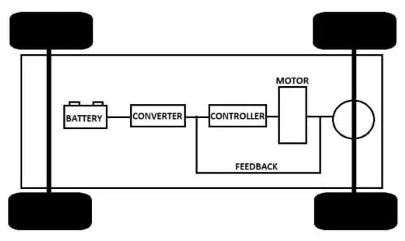
Simulink Model:
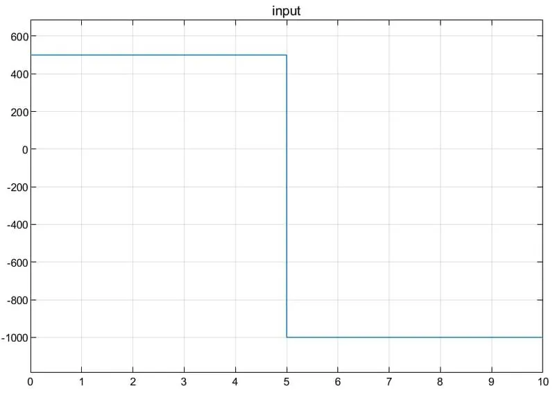
Input:
Output:
From the motor:
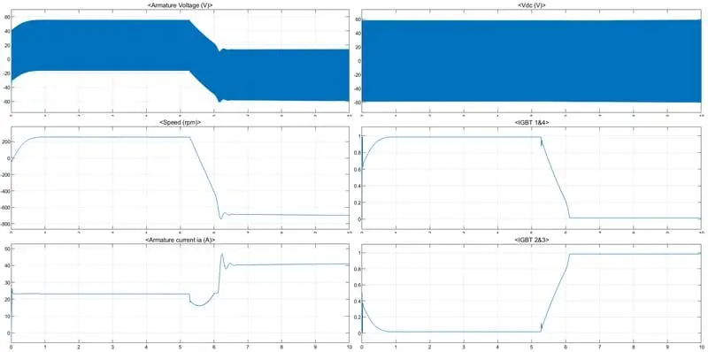
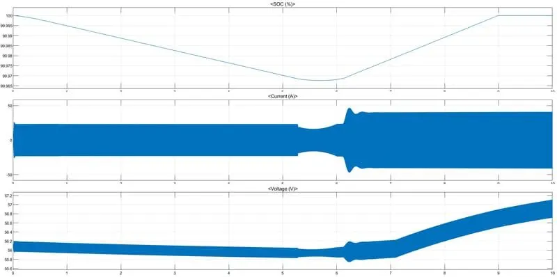
From the Battery:
B. Also, Design the parameters in excel sheet.
Excel Sheet : Click here
Files:
G-Drive Link: Click Here
Reference:
https://www.mgm-compro.com/products/50-80kw-electric-motors/