Week 2- 2R Robotic Arm Challenge
AIM:-
• MATLAB program for simulate the forward kinematics of a 2R Robotic arm.
INTRODUCTION:-
• In industries like Automobile industries & aviation all the processes like welding & painting are automatic, these all the processes are now days automatically done by robots. So, at the design stage of robots designers need to know the workspace (range up to which robot arm can be reach) of the robot for particular operation, so by software like MATLAB designers can easily know range of robot by inserting different size of robotic arm and different angles of robotic arm with reference surface.
• In Robotic field kinematics of the Robot is a very important part, by which we can program & simulate how a robot is going to move. By simulation we can figure out the workspace of the Robot (possible location at which a robot can reach) for design.
GOVERNING EQUATION:-
- We will take a simple Robotic arm with two links for our programming. As per below image L1 (Im) & L2 (0.5 m) are two links of the arm which makes e, & 82 angle with the horizontal axis respectively.
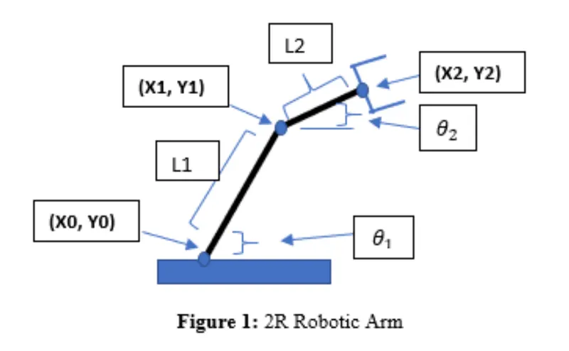
• Equation for calculate co-ordinates of link staring & ending points.
• Co-ordinates of Link1
Starting point = [XO, YO] = [0, 0]
Ending Point = [X1, Y1] = [L1 cosdeθ1, L1 sindθ1]
• Co-ordinates of Link2
Starting point=[X1, Y1] = [L1 cosdeθ1, L1 sindθ1]
Ending Point [X2, Y2] = [X1 + L2 cosdθ2, Y1 + L2 sinθ2,]
OBJECTIVE:-
• We will take multiple values of at the end by stitching all the plots together to make a animation. By closely examine the animation we are able to study workspace or motion of the robotic arm. & 02 range from O to 90 and by all different combinations of those values plots will be created, and
PROGRAM:-
% foward kinematic 2R robotics arm
clear all
close all
clc
%input
% length of link-1(L1)
l1 = 1;
% length of link-2(L2)
l2 = 0.5;
% angle made by link-1 in degrees
theta1 = linspace(0,90,15);
% angle made by link-2 in degrees
theta2 = linspace(0,90,35);
ct =1;
for i = 1:length(theta1)
%taking particular value of a
THETA1 = theta1(i);
% iterating all value of the
for j = 1:length(theta2)
%taking particular value of
THETA2 = theta2(j);
% coordinates of link-1
x0 = 0;
y0 = 0;
% the coordinates of end point of link-1
x1 = l1*cosd(THETA1);
y1 = l2*sind(THETA1);
% the coordinates of end point of link-2
x2 = x1 + l2*cosd(THETA2);
y2 = y1 + l2*sind(THETA2);
% plotting robotic arm
plot([x0 x1],[y0 y1],[x1 x2],[y1 y2],'linewidth',3)
axis([-0.1 1.5 0 1.5]);
%pausing the plot for a while
% plot
pause(.00001)
% capturing the current plot to combine later
M(ct)=getframe(gcf);
% incrementing ct so that each fram is captured in
ct=ct+1;
end
end
% Making movie for collected frames
movie(M);
% Creating a video file of '.avi'
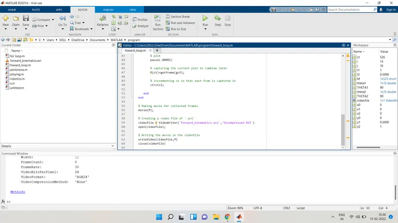
videofile = VideoWriter('forward_kinematics.avi','Uncompressed AVI')
open(videofile);
% Writing the movie in the videofile
writeVideo(videofile,M)
close(videofile)
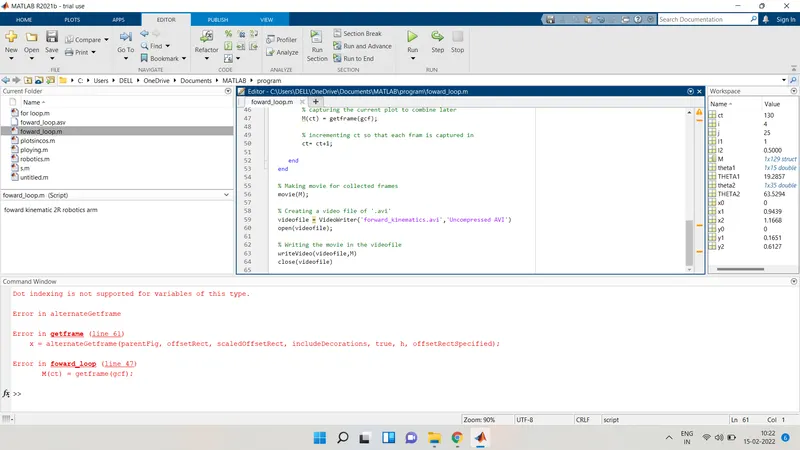
ERROR-
I close the running program in the mid while it's running
LINK OF VIDEO ON YOUTUBE:-
CONCLUSION:-
• After generating animation by examine closely we can understand the workspace of the Robotic arm which is our main purpose.
• By changing length & angles of the links different combinations are possible, plotting graphs for all those different combinations Robot design can be done.