Project-1: Powertrain for aircraft in runways
EV LIVE BATCH 21
1. Search and list out the total weight of various types of aircrafts.
Total weight of the aircraft is the maximum weight at which the pilot is allowed to attempt to take off, called as maximum takeoff weight (MTOW) or maximum gross takeoff weight (MGTOW).
So, MTOW is given by addidng aircraft’s empty weight, fuel Weight, passengers & cargo weight. The aircraft weight components can be given as,
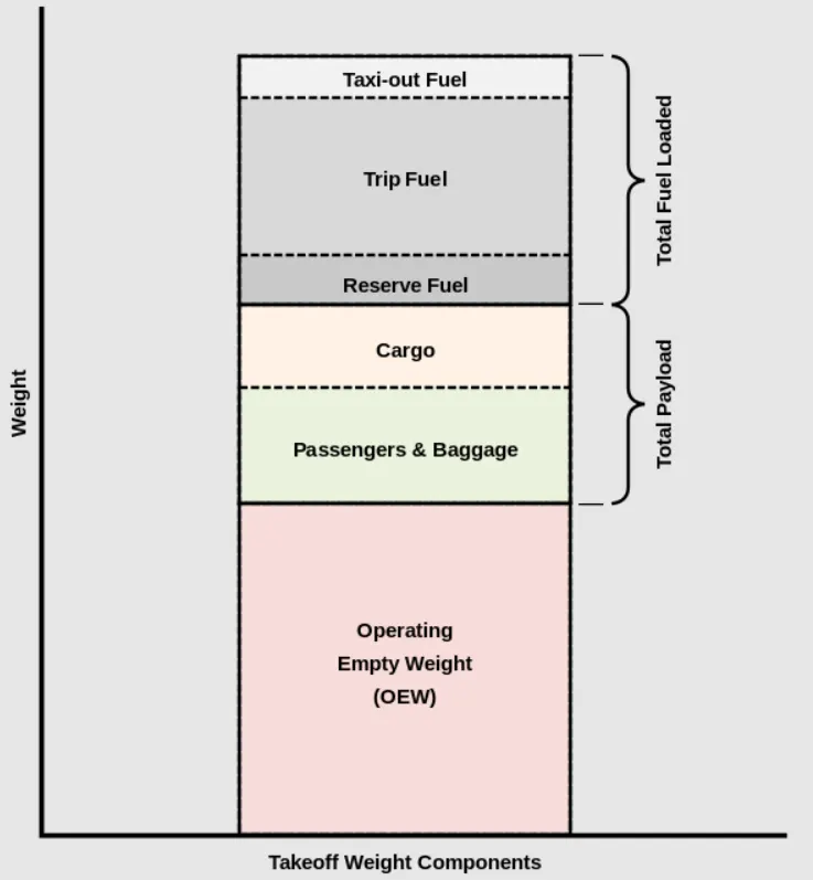
List of Aircrafts having maximum takeoff weight (MTOW) :
| Type | MTOW [kg] |
| Antonov An-225 | 6,40,000 |
| Scaled Composites Model 351 Stratolaunch | 5,89,670 |
| Airbus A380-800[1][2][3] | 5,75,000 |
| Boeing 747-8F | 4,47,700 |
| Boeing 747-8 | 4,43,613 |
| Boeing 747-400ER | 4,12,770 |
| Antonov An-124-100M | 4,05,060 |
| Boeing 747-400 | 3,96,900 |
| Lockheed C-5 Galaxy[4][5][6] | 3,81,000 |
| Boeing 747-200[7] | 3,77,840 |
| Boeing 747-300[7] | 3,77,840 |
| Airbus A340-500[8] | 3,71,950 |
| Airbus A340-600[8] | 3,67,400 |
| Boeing 777F | 3,47,800 |
| Boeing 777-300ER | 3,51,800 |
| Boeing 777-200LR | 3,47,450 |
| Boeing 747-100[7] | 3,40,200 |
| Airbus A350-1000 | 3,08,000 |
| Boeing 777-300 | 2,99,370 |
| Boeing 777-200ER | 2,97,550 |
| Airbus A340-300[8][9] | 2,76,700 |
| McDonnell Douglas MD-11 | 2,73,300 |
| Airbus A350-900 | 2,70,000 |
| Ilyushin Il-96M | 2,70,000 |
| McDonnell Douglas DC-10 | 2,56,280 |
| Boeing 787-9[10] | 2,54,000 |
| Boeing 787-10[10] | 2,54,000 |
| Airbus A340-200[8][11] | 2,53,500 |
| Airbus A330-900 | 2,51,000 |
| Ilyushin IL-96-300 | 2,50,000 |
| Airbus A330-300[12][13] | 2,42,000 |
| Airbus A330-200[12][13] | 2,42,000 |
| Lockheed L-1011-500 | 2,31,300 |
| Boeing 787-8[10] | 2,28,000 |
| Lockheed L-1011-200 | 2,11,400 |
| Ilyushin IL-86 | 2,08,000 |
| Boeing 767-400ER | 2,04,000 |
| Airbus A300-600R[14] | 1,92,000 |
| Boeing 767-300ER | 1,87,000 |
| Concorde | 1,85,000 |
| Airbus A300-600[14] | 1,63,000 |
| Boeing 767-300 | 1,59,000 |
| Airbus A310-300[14] | 1,57,000 |
| Vickers VC10 | 1,52,000 |
| Boeing 707-320B[15] | 1,51,000 |
| Boeing 707-320C[15] | 1,51,000 |
| Douglas DC-8-61 | 1,47,000 |
| Airbus A310-200[14] | 1,42,000 |
| Airbus A400M | 1,41,000 |
| Douglas DC-8-32 | 1,40,000 |
| Douglas DC-8-51 | 1,25,000 |
| Boeing 757-300 | 1,24,000 |
| Boeing 707-120B[15] | 1,17,000 |
| Boeing 757-200 | 1,16,000 |
| Boeing 720B[16] | 1,06,000 |
| Boeing 720[16] | 1,04,000 |
| Tupolev Tu-154M | 1,04,000 |
| Tupolev Tu-204SM | 1,04,000 |
| Convair 880 | 87,500 |
| Boeing 737-900 | 85,000 |
| Boeing 737-900ER | 85,000 |
| Boeing 727-200 Advanced[17] | 84,000 |
| Airbus A321-100[18] | 83,000 |
| Boeing 737-800 | 79,000 |
| Boeing 727-200[17] | 78,000 |
| McDonnell-Douglas MD-83 | 73,000 |
| Boeing 727-100[17] | 72,500 |
| Boeing 727-100C[17] | 72,500 |
| McDonnell-Douglas MD-90-30 | 71,000 |
| de Havilland Comet 4 | 70,700 |
| Boeing 737-700 | 70,000 |
| Airbus A320-100[18] | 68,000 |
| Boeing 737-400 | 68,000 |
| de Havilland Comet 3 | 68,000 |
| Boeing 377 | 67,000 |
| Boeing 737-600 | 66,000 |
| Airbus A220-300 | 65,000 |
| Hawker Siddeley Trident 2E | 65,000 |
| Airbus A319[18] | 64,000 |
| Boeing 737-300 | 63,000 |
| Boeing 737-500 | 60,000 |
| Airbus A220-100 | 59,000 |
| Airbus A318[18] | 59,000 |
| Boeing 717-200HGW | 55,000 |
| Douglas DC-7 | 55,000 |
| de Havilland Comet 2 | 54,000 |
| Boeing 717-200BGW | 50,000 |
| de Havilland Comet 1 | 50,000 |
| Douglas DC-6A | 48,600 |
| Douglas DC-6B | 48,500 |
| Embraer 190[19] | 48,000 |
| Caravelle III | 46,000 |
| Fokker 100 | 46,000 |
| Douglas DC-6 | 44,000 |
| Avro RJ-85 | 42,000 |
| Handley Page Hermes | 39,000 |
| Embraer 175[20] | 37,500 |
| Bombardier CRJ900[21] | 36,500 |
| Embraer 170[22] | 36,000 |
| Bombardier CRJ700 | 33,000 |
| Douglas DC-4 | 33,000 |
| Vickers Viscount 800 | 30,400 |
| Bombardier Q400 | 28,000 |
| Bombardier CRJ200 | 23,000 |
| ATR 72-600 | 22,800 |
| Saab 2000 | 22,800 |
| Embraer ERJ 145 | 22,000 |
| ATR 42-500 | 18,600 |
| Saab 340 | 13,150 |
| Embraer 120 Brasilia | 11,500 |
| BAe Jetstream 41 | 10,890 |
| Learjet 75[23] | 9,752 |
| Pilatus PC-24[24] | 8,300 |
| Embraer Phenom 300[25] | 8,150 |
| Beechcraft 1900D | 7,765 |
| Cessna Citation CJ4[26] | 7,761 |
| de Havilland Hercules | 7,000 |
| Embraer Phenom 100 | 4,800 |
2. Is there any difference between ground speed and air speed?
Airspeed is the speed at which an aircraft is moving relative to the air, in which an aircraft is flying. As such, it’s also the speed at which the air is flowing around the aircraft’s wings.
Similarly, Ground speed is the speed of an aircraft relative to the ground. It is horizontal rather than vertical i.e. if an aircraft is climbing completely vertically upwards, it would have a zero ground speed.
In other words, while airspeed is what determines whether there is enough airflow around an aircraft to make it fly, ground speed is what determines how fast an aircraft will get to its destination.
The relationship between airspeed and ground speed is fairly simple. Ground speed is simply the sum of airspeed and wind speed, i.e. if the aircraft is flying in the same direction as the wind is blowing, the aircraft experiences tailwind, and its ground speed is higher than its airspeed. On the other hand, if the wind is blowing against the direction the aircraft is traveling in, the aircraft experiences headwind, and its ground speed is lower than its airspeed.
Consider an example, an aircraft has an airspeed of 500 miles per hour that has to cover a ground distance of 2,000 miles.
If there is no wind at all, then both the aircraft’s airspeed and ground speed would be the same 500 miles per hour, and the aircraft would reach its destination in 4 hours.
If there was a 100 miles per hour headwind – wind blowing against the aircraft’s direction of travel – the aircraft would still be traveling at an airspeed of 500 miles per hour. However, its ground speed would be just 400 miles per hour (100 miles per hour slower than its airspeed). And as such, it would take the aircraft 5 hours to reach its destinations.
Finally, if there was a 100 miles per hour tailwind – wind blowing in the same direction as the aircraft’s travel – the aircraft would still be traveling at an airspeed of 500 miles per hour, but its ground speed would be 100 miles faster. And, at 600 miles an hour, the aircraft would reach its destination in just 3 hours and 20 minutes.
3. Why is it not recommended to use aircraft engine power to move it on the ground at Airport?
It is not recommended to use aircraft engine power to move it on the ground at Airport so as to avoid some of the significant hazards posed by aircraft engines. When an aircraft's engine is activated, the thrust can create a high-speed wind that can easily cause damage to the airport terminal, surrounding ground vehicles, jetway, baggage and most importantly, ground personnel.
Suppressing the use of engines is especially important when towing a large aircraft, as their more powerful thrust capabilities can become exceedingly dangerous. Engine thrust can easily send any loose items airborne, turn the tiniest grains of dust into hazardous projectiles and create debris that can cause damage to multi-million dollar engines. Additionally, aircraft engines consume a great deal of fuel and generate extreme noise that can be harmful to ground personnel. Using a pushback tug for aircraft is simply a more economical and safer option than running the engines. Also, Towing and pushback tugs for aircraft are also used to make general maintenance easier for ground personnel. When an aircraft needs to be moved to a hangar for maintenance purposes or is not required for flight, the easiest way is to send an aircraft tug to the tow-in gate for transport. Aircraft towing frees up time for the airline, maintenance team, airport ground controllers and pilots who don't need to waste time getting the engines started. It's also not cost-efficient to start aircraft engines just to reposition an aircraft for maintenance purposes. Typically, ground personnel are trained to only need the aircraft brake system when towing a large aircraft.
Also, Pilots do not have a clear view of the ground from the flight deck and thus rely on towing equipments when needed. Once the aircraft is perfectly positioned and far from the terminal tow-in gate and other vehicles, the airport tug is disconnected and the aircraft can use its engines and steering to move to the runway for takeoff.
4. How an aircraft is pushed to runway when its ready to take off?
When an aircraft is pushed to runway when its ready to take off, this process is called as Pushback. As Pilots do not have a clear view of the ground from the flight deck so they have to rely on towing equipments when needed to pushback. Aircraft can use its own engines to do so, but it is not recommended especially for large aircrafts as, their more powerful thrust capabilities can become exceedingly dangerous. Engine thrust can easily send any loose items airborne, turn the tiniest grains of dust into hazardous projectiles and create debris that can cause damage to multi-million dollar engines. Additionally, aircraft engines consume a great deal of fuel and generate extreme noise that can be harmful to ground personnel.
So, once clearance is obtained, the pilot will communicate with the pushback vehicle or tug driver (or a ground handler walking alongside the aircraft in some cases) to start the pushback. Steering is done by the pushback tug driver and not by the pilots. Once the aircraft is perfectly positioned and far from the terminal tow-in gate and other vehicles, the airport tug is disconnected and the aircraft can use its engines and steering to move to the runway for takeoff.
5. Learn about take off power, tyre design, rolling resistance, tyre pressure, brake forces when landing.
- Take off power : Takeoff is the phase of flight in which an aircraft goes through a transition from moving along the ground (taxiing) to flying in the air and the amount of power that an engine is generating for takeoff, is the take off power. Usually the engines are run at full power during takeoff. Following the taxi motion, the aircraft stops at the starting line of the runway. Before takeoff, the engines, particularly piston engines, are routinely run up at high power to check for engine-related problems. This makes a considerable noise. When the pilot releases the brakes, the aircraft starts accelerating rapidly until the necessary speed for take-off is achieved and is depend upon air density, aircraft weight, and aircraft configuration (flap and/or slat position). Air density is affected by factors such as field elevation and air temperature.
- Tyre Design: When it comes to safety, tyres are one of the most important components of aircraft. They help to absorb the shock of landing and provide cushioning. It also provides the necessary traction for braking and stopping of an aircraft. An aircraft tyre is designed to withstand extremely heavy loads while landing, take off, taxing, and parking. The number of wheels required for aircraft increases with the weight of the aircraft, as the weight of the aeroplane needs to be distributed more evenly.
Tyre construction and design can be given as,
a)Tread: The tread is made of rubber mixed with other additives to obtain the desired level of toughness, durability, and resistance to wear. The tread pattern is designed to aircraft operational requirements, with the ribbed tread design used widely due to its good traction under varying runway conditions.
b)Sidewall: The sidewall is a protective layer of rubber that covers the outer casing ply. It extends from the tread edge to the bead area.
c)Tread Reinforcing Ply: One or more layers of fabric that strengthens and stabilizes the tread area for high-speed operation. It also serves as a reference for the buffing process when tires are retreaded.
d)Buff Line Cushion: The buff line cushion is made of rubber compound to enhance the adhesion between the tread reinforcing ply and the breakers or casing plies. It is of sufficient thickness to allow for the removal of the old tread when the tire is retreaded.
e)Breakers: Breakers are reinforcing plies of rubber-coated fabric placed under the buff line cushion to protect casing plies and strengthen and stabilize the tread area. They are considered an integral part of the casing construction.
f)Casing Plies: Alternate layers of rubber-coated fabric (running at opposite angles to one another) provide the strength of the tire.
g)Wire Beads: Hoops of high tensile strength steel wire that anchor the casing plies and provide a firm mounting surface on the wheel. The outer edge of the bead that fits against the wheel flange is called the bead heel. The inner bead edge is called the bead toe.
h)Apex Strip: A wedge of rubber affixed to the top of the bead bundle.
i)Flippers: Layers of rubberized fabric that help anchor the bead wires to the casing and improve the durability of the tire.
j)Ply Turnups: The casing plies are anchored by wrapping them around the wire beads, thus forming the ply turnups.
k)Chafer: A protective layer of rubber and/or fabric located between the casing plies and wheel to minimize chafing.
l)Liner: In tubeless tires, the liner is a layer of low permeability rubber that acts as a built-in tube and restricts gas from diffusing into the casing plies. In tube-type tires, a thinner liner is used to prevent tube chafing against the inside ply.
- Rolling Resistance: Rolling resistance is the opposing force a rolling body in motion experiences when it comes in contact with a surface. In other words, Tire rolling resistance is the energy that an aircraft needs to send to tires to maintain movement at a consistent speed over a surface. In other words, it is the effort required to keep a tire rolling. The main contributor to rolling resistance is the process known as hysteresis. Hysteresis is essentially the energy loss that occurs as a tire rolls through its footprint. The energy loss must be overcome by the engine, which results in wasted fuel.
Considering an aircraft, rolling resistance is influenced by a number of factors as follows:
- Natural rubber tyres tend to have lower rolling resistance than those made from synthetic rubber.
- Cross-ply tyres have higher rolling resistance than radial ply.
- The number of carcass plies and tread thickness increase the rolling resistance due to increased hysteresis.
- Hard smooth dry surfaces have lower rolling resistances than rough or worn out surfaces.
- The inflation pressure decreases the rolling resistance on hard surfaces.
- Increasing the wheel and tyre diameter reduces the rolling resistance only slightly on hard surfaces but it has a pronounced effect on soft ground
- Increasing the tractive effort also raises the rolling resistance due to the increased deformation of the tyre carcass and the extra work needed to be done.
- Tyre pressure: When it comes to safety, tyres are one of the most important components of aircraft. They help to absorb the shock of landing and provide cushioning. It also provides the necessary traction for braking and stopping of an aircraft. An aircraft tyre is designed to withstand extremely heavy loads while landing, take off, taxing, and parking.
Aircraft tires generally operate at high pressures, up to 200 psi (14 bar) for airliners and even higher for business jets. The main landing gear on the concorde was typically inflated to 232 psi (16 bar), whilst its tail bumper gear tires were as high as 294 psi (20.3 bar). Tests of airliner aircraft tires have shown that they are able to sustain pressures of maximum 800 psi (55 bar) before bursting. Making sure that the aircraft tires are properly inflated is a crucial part of preflight and routine service checks which can go a long way to maximizing tire utilization and minimizing risks to safe operations.
The use of an inert gas for tire inflation eliminates the possibility of tire explosion. So, aircraft tires are usually inflated with nitrogen to minimize expansion and contraction from extreme changes in ambient temperature and pressure experienced during flight.
Improper tire pressure maintenance can have serious consequences for aircraft safety, so to avoid those consequences is to check tire pressures regularly and service them as necessary. Following these three actions is a good way to make sure you get the most value out of your tires and contribute to the safe operation of your aircraft:
a. Perform daily pressure checks with a calibrated gauge.
b. Target the highest pressure recommended.
c. Compensate for ambient temperature changes.
- Brake Forces when Landing: For landing, Airplanes rely on a braking system. Brakes are used not only to decelerate during a landing run, but also to hold the aircraft during an engine run-up, and in some cases to steer the aircraft through differential braking. At cruising altitude, most commercial airplanes fly at a speed of roughly 500 to 600 mph. When landing, however, they must reduce their speed and upon touching the runway, airplanes must quickly brake until they come to a complete stop. Aircraft braking system includes, disk brakes, air brakes, auto brakes, Wing spoilers, Flaps, Thrust reversal
The forces acting on an aircraft in straight-and-level, unaccelerated flight are thrust, drag, lift, and weight.
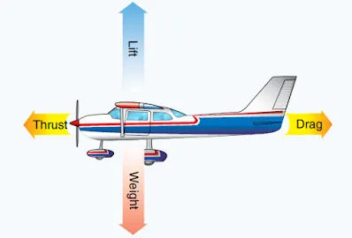
In steady flight, the sum of these opposing forces is always zero. There can be no unbalanced forces in steady flight. It does not mean the four forces are equal. It means the opposing forces are equal to, and thereby cancel, the effects of each other i.e. thrust equals drag and lift equals weight.
Now while landing, Equilibrium is required for a steady descent. If, while in level flight, the thrust is removed there will be no force balancing the drag. In order to maintain flying speed, the nose of the airoplane must be lowered.
With the nose lowered and weight still acting down towards the centre of the earth, there is now a forward component of weight (FCW) that balances drag. State that for equilibrium there must be a force equal and opposite to weight. This force R is made up of lift and drag. Therefore, the aeroplane is in equilibrium.
Thrust controls the rate of descent/landing. The more thrust given, the less the rate of landing. It also reduces the descent angle and increases the distance travelled by aircraft over the ground, increasing the range from a given altitude. The ratio of lift to drag is a measure of the efficiency of the wing i.e. the higher the lift to drag ratio, the further the aeroplane will glide. If this ratio chnaged by increasing the drag (by extending flap or flying at an incorrect airspeed) a greater forward component of weight is required to balance the drag. When an aircraft is flying at its best Lift/Drag ratio, an increase in weight will increase the Forward Weight component, increasing the speed down the slope, and therefore the rate of landing.
7. A. Design an electric powertrain with type of motor, it’s power rating, and energy requirement to fulfill aircraft towing application in Simulink. Estimate the duty cycle range to control the aircraft speed from zero to highest. Make all required assumptions. Prepare a table of assumed parameters. Draw a block diagram of powertrain.
(Hint :DC7 Block)
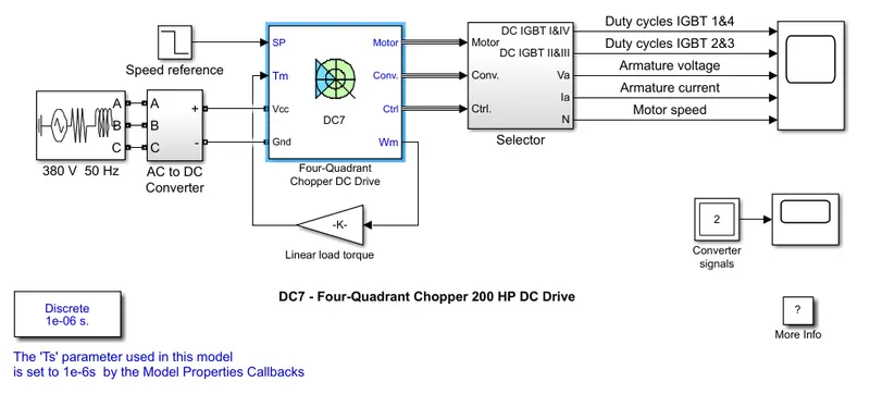
The DC7 block model can be given as,
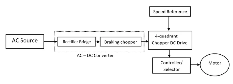
It can be represented in block diagram as follows
Description
A four quadrant chopper is a chopper which can be operated in all the four quadrants. The power or energy can flow either from source to load or load to source in this chopper. In first quadrant, chopper acts as a step down chopper whereas in second quadrant it behaves as a step up chopper.
The 200 HP DC motor is separately excited with a constant 150 V DC field voltage source. The armature voltage is provided by an IGBT converter controlled by two PI regulators. The converter is fed by a 515 V DC bus obtained by rectification of a 380 V AC 50 Hz voltage source. In order to limit the DC bus voltage during dynamic braking mode, a braking chopper has been added between the diode rectifier and the DC7block.
The first regulator is a speed regulator, followed by a current regulator. The speed regulator outputs the armature current reference used by the current controller in order to obtain the electromagnetic torque needed to reach the desired speed. The speed reference change rate follows acceleration and deceleration ramps in order to avoid sudden reference changes that could cause armature over-current and destabilize the system.
While the current regulator controls the armature current by computing the appropriate duty ratios. For proper system behaviour, the instantaneous pulse values of IGBT devices 1 and 4 are opposite to those of IGBT devices 2 and 3. This generates the average armature voltage needed to obtain the desired armature current. In order to limit the amplitude of the current oscillations, a smoothing inductance is placed in series with the armature circuit.
Results obtained can be given as,
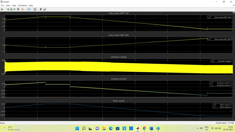
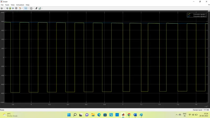
The 4 IGBT's duty cycle, motor armature voltage and current, the motor speed on the scope. The current and speed references are also shown.The motor is coupled to a linear load, which means that the mechanical torque of the load is proportional to the speed.The speed reference is set at 500 rpm at t = 0 s. Observe that the motor speed follows the reference ramp accurately (+400 rpm/s) and reaches steady state around t = 1.3 s.The armature current follows the current reference very well, with fast response time and small ripples.
At t = 2 s, speed reference drops to -1184 rpm. The current reference decreases to reduce the electromagnetic torque and causes the motor to decelerate with the help of the load torque. At t = 2.2 s, the current reverses in order to produce a braking electromagnetic torque (dynamic braking mode). This causes the DC bus voltage to increase. At t = 3.25 s, the motor reaches 0 rpm and the load torque reverses and becomes negative. The negative current now produces an accelerating electromagnetic torque to allow the motor to follow the negative speed ramp (-400 rpm/s). At t = 6.3 s, the speed reaches -1184 rpm and stabilizes around its reference.