Project-1: Powertrain for aircraft in runways
Aim:-Powertrain for aircraft in runways.
Objectives:
1. Search and list out the total weight of various types of aircrafts.
2. Is there any difference between ground speed and air speed?
3. Why is it not recommended to use aircraft engine power to move it on the ground at Airport?
4. How an aircraft is pushed to runway when its ready to take off?
5. Learn about take off power, tyre design, rolling resistance, tyre pressure, brake forces when landing.
6. A. With necessary assumptions, calculate the force and power required to push / pull an aircraft by a towing vehicle.
7.A. Design an electric powertrain with type of motor, it’s parameters to fulfill aircraft towing application in Simulink. Estimate the duty cycle range to control the aircraft speed from zero to highest. Make all required assumptions. Prepare a table of assumed parameters. Draw a block diagram of powertrain.
Part 1:
Study-1:
Weight is major factor in airplane construnction and operaion, and it demands respect from all pilots and pertiular diligence by all mainatenance personnel.
Excessive weight reduces the efficiency of an aircraft and the available safety margin if an emergency condition should arise.
The total weight is the maimum take-off weight.
It ia the maximum mass at which the aircraft is certified for take-off due to structural or other limits.
MTOW = Maximum take-off weight,
MLW = Maximum landing Weight,
TOR = Take-off run,
LR = Landing run.
Maximum take-off weight:
The maximum weight limits for an aircraft to begin its take-off roll called the max. take-off weight.
Maximum landing Weight:
The Maximum landing weight is, as you might imagine, the maximum aircraft wight limit approved for an aircraft to land. Landing weight structural damage.
This is a list of aircraft sorted by maximum takeoff weight.
Contents
- Airplanes
- Helicopters
- Convertplanes
Weight class is based are desighned by APO130 based on the TFMS observed aircraft codes.
There are 6 categories,
A) Heavy, D) Large Commuter,
B) B757, E) Medium,
C) Large Jet , F) Small.
A) Heavy: Any aircraft weighing more than 255,000 lb such as the Boeing 747 or the Airbus A340.
B) B757: Boeing 757 all series.
C) Large Jet: Large jet aircraft weighing more than 41,000 and up to 255,000 lbs such as the Boeing 737 or the Airbus A320.
D) Large Commuter: Large non-jet aircraft (such as the Aerospatiale/Alenia ATR-42 and the Saab SF 340), and small regional jets (such as the Bombardier Canadair Regional Jet), weighing more than 41,000 and up to 255,000 lbs.
E) Medium: Small commuter aircraft including business jets weighing more than 12,500 up to 41,000 lbs such as the Embraer 120 or the Learjet 35.
F) Small: Small, single, or twin engine aircraft weighing 12,500 lbs or less such as the Beech 90 or the Cessna Caravan.
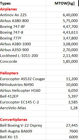
MTOW[kg]: Maximum Take-off weight in kg
Study-2:
Difference between Ground Speed and Air Speed
| Ground speed | Airspeed |
| Ground speed is the airplane's speed relative to the surface of the earth |
Air speed is the speed relative to the air it is flying in. |
| Ground speed is what determines how fast an aircraft will get to its destination | Airspeed is what determines whether there is enough airflow around an aircraft to make it fly |
| Ground speed is simply the sum of airspeed and wind speed. | It is independent of ground speed. |
Ground Speed
For a reference point picked on the ground, the aircraft moves relative to the reference point at the ground speed. Ground speed is also a vector quantity. So a comparison of the ground speed to the wind speed must be done according to rules for Vector comparision.
Wind Speed
For a reference point picked on the ground, the air moves relative to the reference point at the wind speed.The wind speed is a vector quantity and has both a magnitude and a direction. A positive velocity is defined to be in the direction of the aircraft's motion. We are neglecting cross winds, which occur perpendicular to the flight path but parallel to the ground, and updrafts and downdrafts, which occur perpendicular to the ground.
Airspeed
The important quantity in the generation of lift is the relative velocity between the object and the air, which is called the airspeed. Airspeed cannot be directly measured from a ground position, but must be computed from the ground speed and the wind speed. Airspeed is the vector difference between the ground speed and the wind speed.
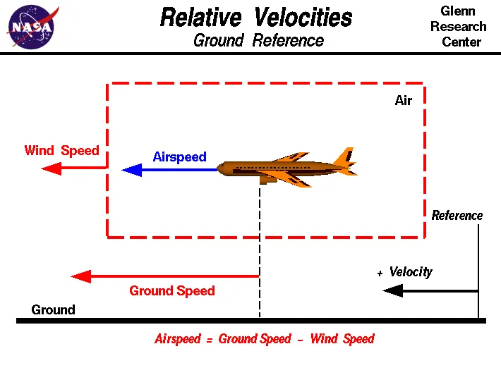
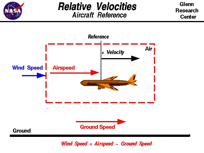
From the above two figures indicates that relative velocity with respect to the aircraft reference and ground reference.
The aircraft usually operate on land as well as in air and so we need to study their speed difference in ground and in air.
The ground speed and he airspeed usually chnge based on the wind component.
If we consider that there is no wind component then, ground speed = airspeed Speed
If the wind is blowing in the tail direction of the aircraft then (airspeed > ground speed) so, airspeed = Ground Speed + Wind component
If the wind is blowing in the head direction of the aircraft then (airspeed < ground speed) so, airspeed = Ground Speed - Wind component
Also gravity plays a mojor role in increasing the aircraft's speed whileit is descending.
Here wind speed is the vector difference between ground andairspeed. On a perticular day, the wind speed may be zero ad it is equal to the ground speed.
If the measured airspeed is greater than the observed groundspeed the wind speed become positive.
Study-3:
For movement on the ground the aircraft uses it own engine power, which is called taxing.
Althogh many aircrafts are capable of moving in backward using reverese thrust, as result the jet blast or pop wash might cause damage to the terminal building or equipment.
Engine close to ground many also blow sand and debris forward and then suck them into the engine, causing damage to the engine. Therefore there are pushback trucks in the airport.
A pushback truck lifts the front wheel of the aircraf, their role in most airports is to move the aircraft away from the parking spot on to the taxiways, which is called towing.
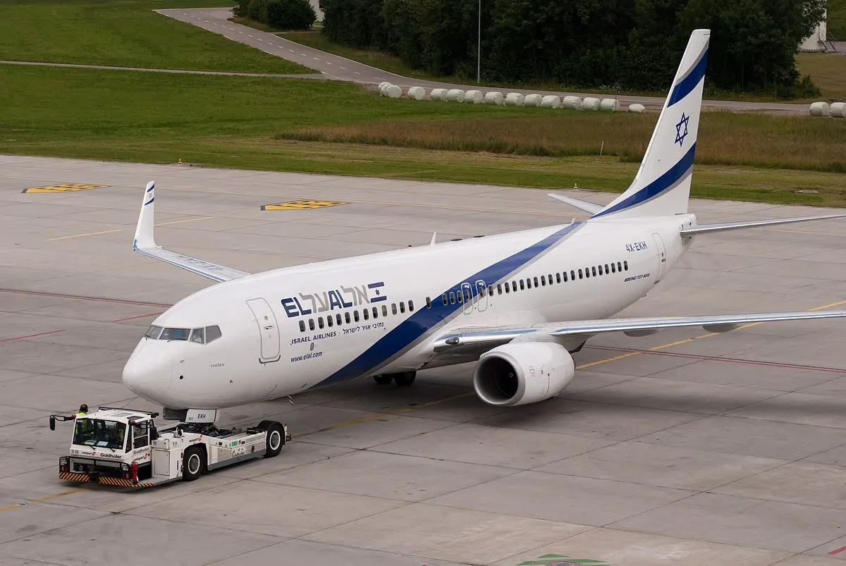
Although most aircraft are capable of moving themsleves backwards on the ground using reverese thrust, a procedure called as powerback, it is not typically done due to the following reasons:
- Effectively a loss of control can happen, especially during high power engine running. Damage can occure to the aircraft itself, other aircraft nearby or to airside structures.
- There is a risk of injury to ground support personal who may be in relatively close proximity to the aircraft.
- It is easier for truck driver to see the surroundings better than the pilot sitting in he cockpit with limited window. The pushback driver knows the airport better than the pilot.
- It also saves fuel. virgin Atlantic had proposed a new system in which pushback truck will move the aircraft all the way to runway to save fuel and reduce impack of environment.
- The plane engines are very loud. When more than one plane will add up their sound, than it will not be pleasent for passangers and others near airport.
Study-4:
Airplanes have engines, and they can use them to move forward along the ground. So they push themselves to the runway.
It is true that most of the time, a small vehicle is needed to push the larger commercial airplanes backwards away from the terminal building, because even if a plane can reverse it’s thrust, it’s not always safe to hit the buildings with that reverse thrust. So the little trucks push the bigger planes back away from the buildings, but after that, the planes can apply a small amount of engine power to roll forward just as all airplanes can.
Aircraft push themselves to the runway.
- The pilot parks the aircraft in exactly the right place. Usually with the help of an automatic system, but occasionally guided by a marshaller waving two paddles or wands. Dozens of handling personnel are already standing by to perform a whole range of tasks simultaneously.
- As soon as the aircraft is stationary and the engines are switched off, the first priority is to disembark the passenger as quickly as possible. The apron handler places chocks in front of the wheels and connect the ground power. Meanwhile, the passenger bridge manoeuvres up to the door and a belt loader rolls up to the cargo hold. Luggage is unloaded and transferred to the terminal on baggage carts.
- Refuelling begins, usually from a hydrant at the stand. A hose is attached to this from a special vehicel called dispenser, with the other side connected to the fuel tank in the wing
- Now it is time to service the aircraft. The caterer loads new meals and takes away the food waste and use cutlery and crockery. Other activities include draining the lavatories, replacing the headrest covers, removing rubbish and distibuting fresh blankets and in-flight magazine.
- A specialist team or sometimes the crew themselves- cleans the cabin so that the new passengers boared a pristine aircraft.
- Meanwhile, specialist from thr airline conduct a technical check to make sure that the engines, wings, control surfaces, landing gear, instruments doors and others equipment are in full working order.
- The aircraft is now ready for baggage to be loaded for the next flight. This is a quick process, on average taking only 10-15 min. A little letter the passengers to start boarding. As soon as they are all in their seats, the door is closed and the pilot informsair traffic control that the fl9ight is ready for departure.
- The apron handler reoves the chocks.A so called pushback truck reverese the aircraft into taxiing position, pushing it with a towbar attached to the nose-wheel strut. Or, in most modern vesions, by actually lifiting the wheel. The speed up coupling and decoupling.
- The aircraft taxis to the runway to depart at the agreedtime.
- The pilot waits for permission to take off from air-traffic control. This is possible once to departure route is clear. As soon as the go ahead is received, the plane takes to the air at full power.
Study-5:
Take-off Power:
Take-off (T-O) is the phase of flight in which an aerospace vehicle leaves the ground and becomes airborne.For aircraft that take off horizontally, this usually involves starting with a tarnision from moving along the ground on arunway. For light aircraft, usually full power is used during take-off.
Large transport category aircraft may use a reduced power for take-off, where less than full power is applied in order to prolong engine life, reduce maintanance costs and reduce noise emissions.
The aircraft is permitted to accelerate to rotation speed. The term rotation is used to because the aircraft pivots around the axis of its main landing gear while still on the ground, usually because of gentle manipulation of the flight controls to mae or facilitate this change in aircraft attitude and once proper air displacement occurs under or over the wings, an aircraft will lift on its own.
Generally, the T-O phase is split into the segments shown in figure below.
The ground roll is the distance from brake release to the initiation of the rotation, When the pilot pills the control wheel (or stick or yoke) backword in order to raise the nose of the aircraft.
This maneuver is required to increase the area of attack of the airplane to help it become airborne.
The aircraft typically remains in this attitude for some 1-3 sec, depending on aircraft size, before the tires lose contact with the ground. This segment is called the rotation. The rotation phase concludes as the aircraft lifts of the ground and begins the transition and subsequent climb phase.
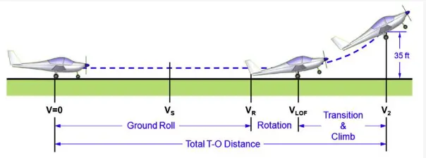
Here V is the instantaneous airspeed of the aircraft, VR is the ground run speed ,VLOF is the lift off for rotation speed, V2 is the climb speed and Vs is the stalling speed in the T-O configuration. This means that if the airplane features high-lift devices, Vs refers to the stalling speed with flaps deployed.
The importnat point is that the airplane must accelerate from standstill to a given airspeed, called the lift-off speed, before it can, well, lift off.
Generally the take of speed or the climb speed of the aircraft (V2) is calculated as,
V2 = 1.2Vs
Where the stalling speed at theTake-Off configuration is given as,
Vs = √(2W/ρSCL, max)
In the above equation,
W= Gross weight of the aircraft,
ρ = Free stream density of air,
S = Wing area of the aircraft,
CL, max = maximum lift coefficient.
the take-off speed required varies with aircraft weight and aircraft configuration, the heavier the weight, the greater the speed needed.
Typical take-off air speeds for jetliners are in the range of 240-285 km/h, light aircraft take off at around 100 km/h and ultra lights have even lower take-off speeds.
Tyre design:
When it comes to safety tyres are one of the most important components of aircraft.
They help to absorb the shock of landing and provide cushioning. It also provides the necessary traction for braking and stopping of an aircraft.
An aircraft tyre is designed to withstand extreamly heavy loads while landing, take off , taxing and parking.
The number of wheels required for aircraft increases with the weight of the aircraft, as the weight of the aeroplane needs to be distributed more evently.
A 737NG & MAX uses 6 wheels, Boeing 787 uses 10 wheels, Boeing 777 uses 14 wheels, Airbus A380 uses 22 wheels.Aircraft tyres work under extreme conditions, carrying up to 340 tons and accelerating at over 250 km/hr at takeoff, in addition to enduring varied environmental stress when in flight and taxing.
Design and Construction of Aircraft tyre:
Carcass plies are used to form the tire. They are sometimes called casing plies. An aircraft tyre is constructed for the purpose it serves.
They support the weight of an aircraft while it is on the ground .
It also provides the necessary traction for braking and stopping of an aeroplane.
Tyre also helps to absorb the shock of landing and provide cushioning the roughness of takeoff, roll-out and taxi opeations.
Unlike an automobile or truck tyre, it does not have to carry a load for a long period of continuous operation. However, an aircraft tyre absorbs the high impact loads of landing and also it's operating at high speeds for a short time when required.
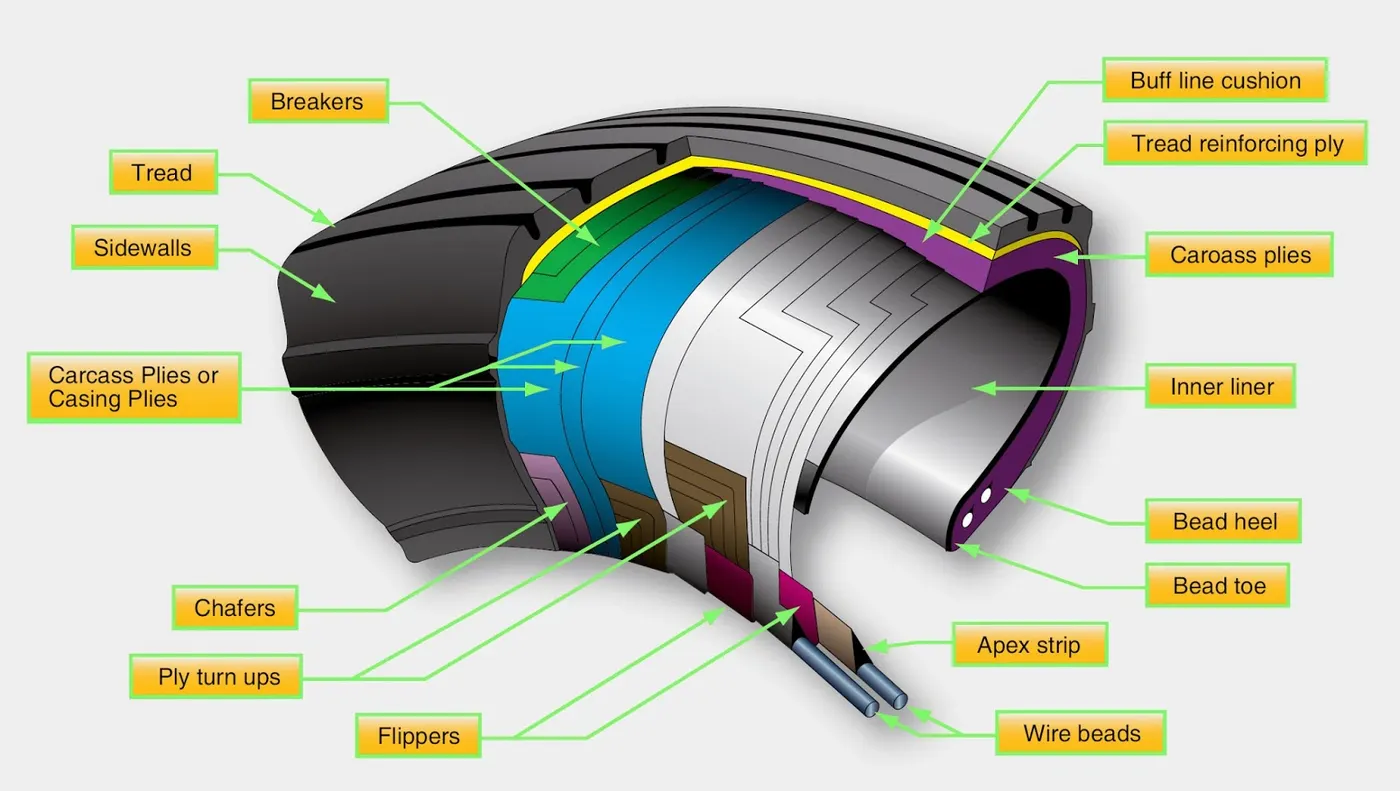
Some technical aspect of the tyre:
Retrading- It is the methodes of restoring a worn tyre by renewing the tread area or by renewing the tread area plus one or both side walls.
Repairs are included in the tyre retreading process.
Load Rating- Load Rating is the maximum permissible load at a specified inflation pressure.
Ply rating- Ply Rating is used to identify the maximum recommended load rating and inflation pressure for a specified tyre.
It is an index of tyre strength.
Speed Rating - The speed rating is the aximum takeoff speed to which the tyre has been tested.
Skid Depth- Skid Depth is the distance between the tread surface and deepest groove as measured in the mould.
today's tyre are conductive. Aircraft tyre are manufactured with tread rubber with conducting compounds to permit earthing static charges.
In early days when tyres were not sufficiently conductive,aircraft used to have aconductive strip hanging down from the axel of the landing gear.
Upon landing this strip would be the first part of the airraft to touch the earth. This discharges any static electricity accumulated on the outer susurface of the aircraft.
Rolling Resistance
In addition to the familier like thrust, weight, lift,drag there is a rolling resistance force FR caused by friction between tyre and ground .When aircraft is towing r taxing to pushed it into runway or when take off roll is happening, the rolling resistance force acts against the traction force of the aircraft.
This rolling resistance force depends on many factors like surface of the road, roughness of the road, dry or wet condition of the road, tyre pressure, tyre material, yre temperature, thread pattern of the tyre etc, which determines the rolling resistance force.
Rolling Resistance Force = FR in Newton
Rolling Resistance co-efficient = μrr (It varries for differen types of environment)
μrr Typical Values for Aircraft-
SURFACE BRAKES OFF BRAKES ON
Dry concrete/ 0.03-0.05 0.3-0.5
asphate
Wet concrete/ 0.05 0.15-0.3
asphate
Icy concrete/ 0.02 0.06-0.10
asphate
Hard turf 0.05 0.4
Firm dirt 0.04 0.3
Soft turf 0.07 0.2
Wet grass 0.08 0.2
Rolling resistance force Frr = μrr * m * g
Where,
m = total mass of the aircraft (Actual mass + Payload) in kg
g = Gravitational constant, that is 9.8 m/s^2.
Tyre Presure
The pressure generally is very high in an aircraft tire to reduce the rolling resistance and to withstand the weight. usually the tyre pressure will be around 190 to 320 psi ased on the type of aircraft. Aircraft tyres are usually inflated with nitrogen to minimize expansion and contraction from extreme changes in ambient temperature and pressure experienced during flight.
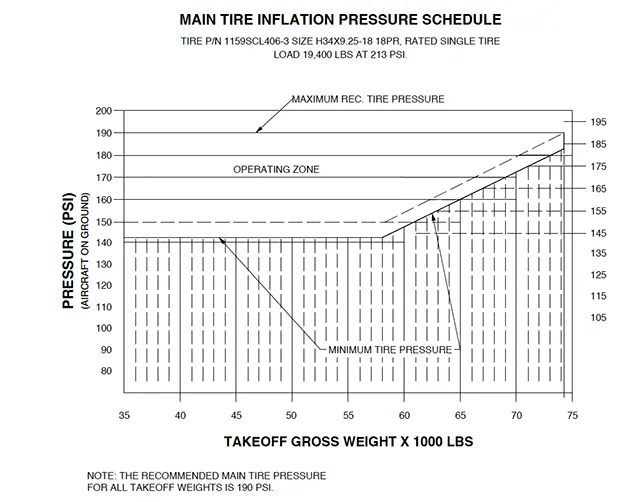
According to U.S. Fedral Aviation Administation (FAA) Technical Standard Order TSO-C62c, the maximum allowable tire pressure loss is 5% per day.
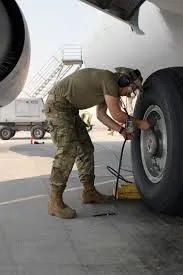
Brake force When Landing:
Stopping an aircraft landing a 180-200 mph requires a lot of braking force. To so this, the aircraft has brake unit on each of the wheels on the main gear assembly. On landing, pilots should use aerodynamic braking by applying extra back- pressure on th stick or yoke. Extreme caution should be used whn applying brakes at any significant speed, and only when the end of the runway is quickly approaching. Never step on the brakes to make a runway exit. Applying the brakes at too high a speed could burn the tires, wear out the brakes, or result in a ground loop or swerve.
Aircraft braking system included:
Aircraft Disc Brake:
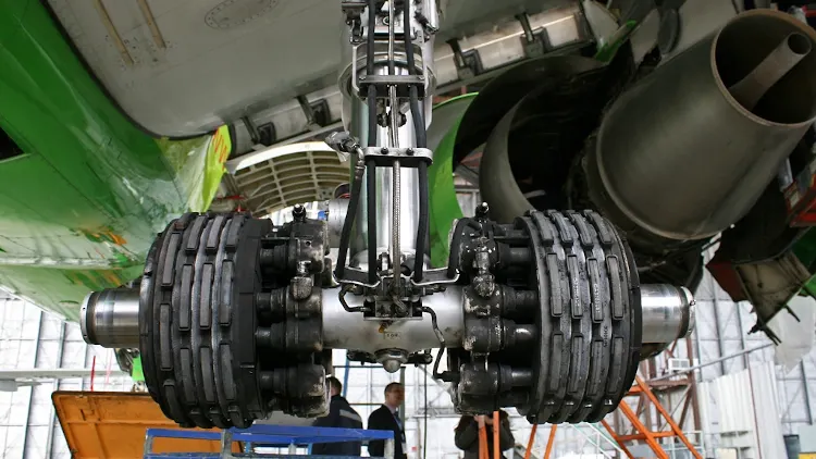
In the landing gear it is used to brake the wheels while touchinh the ground.These brakes are operated hydraulically. In most modern aircraft hey are activated by the top sction of the rudder pedals("toe brakes"). In some older aircraft the bottom section is used instead("heel brakes"). Levers are used in a few aircraft. Most aircraft are capable of differential braking.
Thrust Reverse:
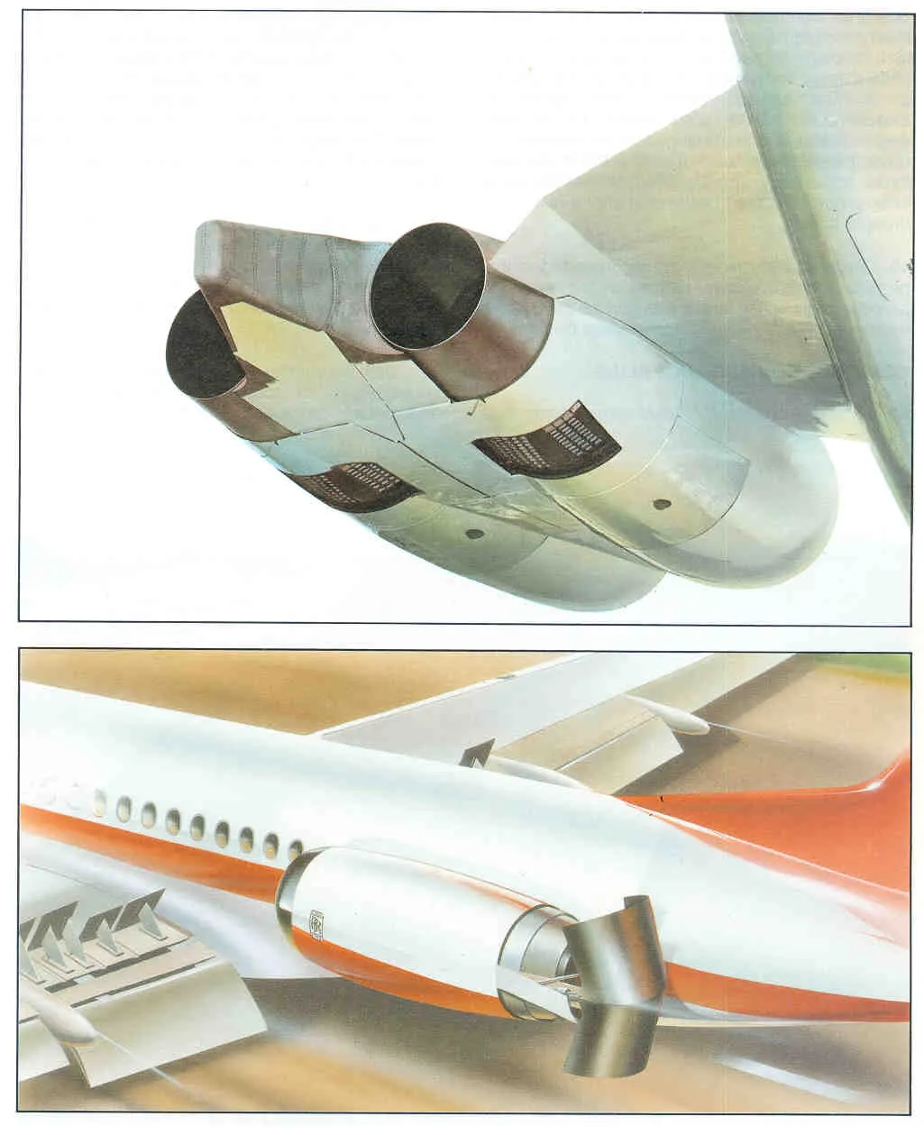
That allow thrust from the engines to be used.
Air Brake:
It is dedicated flight control surface, hat work by increasing drag.
Drogue Parachute:
It is by several former and current military and civilian aircraft (example include the American B-52 and the soviet Tu-134 and Tu-144).
Part B:
Study-6:
The different forces involved when the plane is moved by a tow vehicle:
To proceed for calculating the force and power required to push or pull an aircraft by a towing vehicle, we will assume thefollowing parameters:
Here we will conside aircraft and towing vehicle as separate units. We will also consider acting on aircraft as well as towing vehicle which are;
Rolling Friction Force
Acceleration Force
Aerodynamic drag force
We will neglect the all the losses for calculations.
The total mass of the aircraft including payload for aibus a 380 is 575,000kg
Aircraft Calculations:
Mass of aircraft, mA = 575,000kg
Mass of pushback is 1000kg(assume)
Coefficient of rolling resistance (Crr) = 0.002
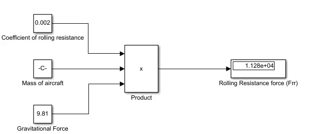
Rolling resistance (Frr) = Crr * m * g
For the Aircraft, Frr = 0.002*575,000*9.81
Frr = 11.2815kN
For the Towing Vehicle, Frrt = 0.002*1000*9.81
Frrt = 19.61N
As the towing vehicle resistance is very less compared to aircraft, since it is a heavy vehicle this resistance can be neglected.
Aerodynamic resistance, (Far)
Given
Drag coefficient Cd = 0.025
Air density ρ = 1.125kg/m^2
Fronatal Area A = 150 m^2
Velocity v = 14.5kmph or 4m/s
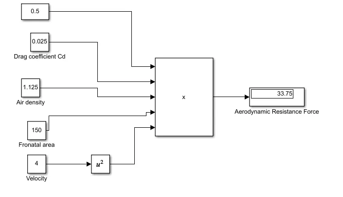
Far = (1/2)*Cd*ρ*V^2
Far = (1/2)*0.025*1.125*150*(4)^2
Far = 33.75N
Total Force = 11281.5 + 33.75
= 11315.25 N
As the tow vehicle and plane moving at alow speed this force can be neglected
Hill Climbing resistance:
Runways are constructed flat so gradient force or hill clambing force is neglected.
Total Traction Force:
Fte = Frr
= 11281.5
Power required
P = Ft*v
= 11315.25*4
= 45.26kW
Since the minimum power required at the tow vehicle is 45.126kW to taxi a heavy aircraft at 4m/s.
B. The Model for calculate force and power using Simulink:
Mathematical model of rolling resistance force:
Mathematical model of Aerodynamic force:
Mathematical model of the Total force and power required by the vehicle to push/pull the aircraft: 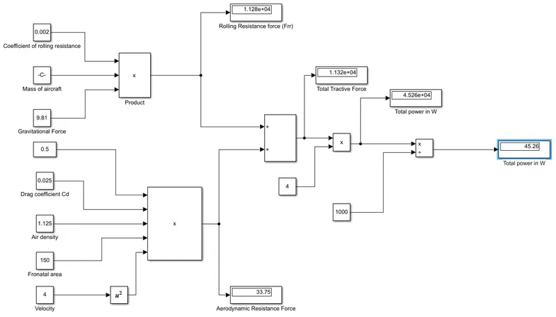
- Constant blocks are used to feed the parameters such as mass, coefficient and other parameters.
- Using product block the resistive forces are calculated.
- Sum blocks are used to calculate the total resistive force.
- The outputs are visualizing using display blocks.
Study - 7 :
Design an electric powertrain with type of motor, it's power rating and energy requirement to fulfill aircraft towing application
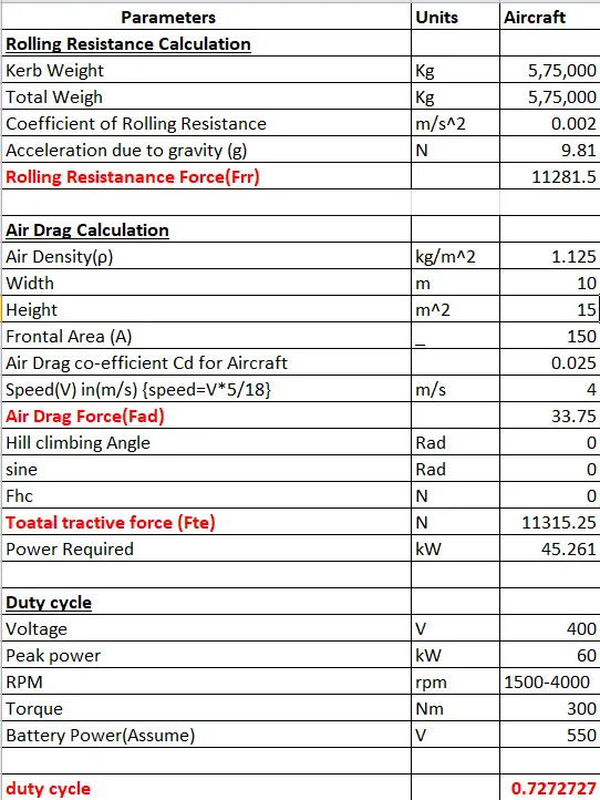
Assumption For Powertrain Design
The power required by the aircraft is 45.26kW. Consider a motor with following specifications
Voltage 400-800V
Peak Power 60-70kW
RPM 1500-4000
Torque 300Nm
Transmission
consider 60kW as peak power therefore voltage will be 400V.
Assume battery power to be 550V.
Now we can calculate the duty cycle
d=Vo/Vs
= 400/550 = 0.7272
Duty cycle is the 0.7272
Assume parameterss
Parameter value
Aircraft Mass (mA) = 575,000kg
Towing vehicle Mass =50,000kg(assume)
Rolling Resistance Co-efficient (Crr) = 0.002
Air density ρ = 1.125kg/m^2
Towing vehicle Drag coefficient Cd = 0.5
Aircraft Drag co-efficient =0.09
Fronatal Area A = 150 m^2
Inclination angle = 0 rad
Tyre Pressure = 203PSI/14 bar
Towing Velocity (V) = 14.5kmph or 4m/s
Towing Time(t) = 2 min
Radius of the towing vehicle wheel = 0.38
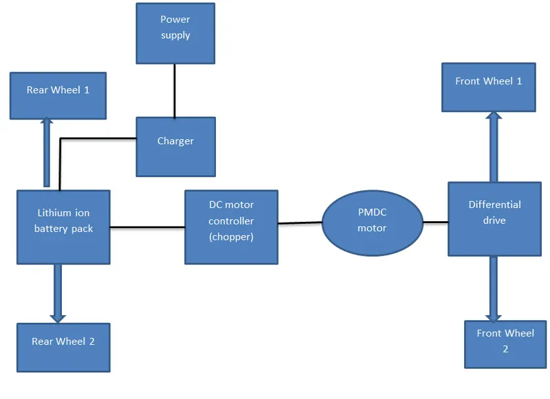
Block diagram of powertrain:
Simulink Model:
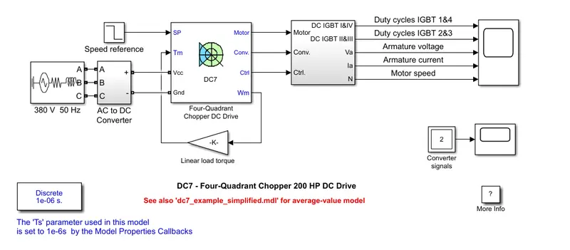
The above figure shows that powertrain arrengement of tow tractor for towing aircraft. The battery source is displayed at the left. The battery parameters are the maximum voltage value of selected motor. The motor characteristics is implementedas calculated above.
The 200 HP DC motor is separately excited with a constant 150 V DC field voltage source. The armature voltage is provided by an IGBT converter controlled by two PI regulators.
The converter is fed by a 515 V DC bus obtained by rectification of a 380 V AC 50 Hz voltage source. In order to limit the DC bus voltage during dynamic braking mode, a braking chopper has been added between the diode rectifier and the DC7 block.
The first regulator is a speed regulator, followed by a current regulator. The speed regulator outputs the armature current reference (in p.u.) used by the current controller in order to obtain the electromagnetic torque needed to reach the desired speed.
The speed reference change rate follows acceleration and deceleration ramps in order to avoid sudden reference changes that could cause armature over-current and destabilize the system.
The current regulator controls the armature current by computing the appropriate duty ratios of the 5 kHz pulses of the four IGBT devices (Pulse Width Modulation).
For proper system behaviour, the instantaneous pulse values of IGBT devices 1 and 4 are opposite to those of IGBT devices 2 and 3. This generates the average armature voltage needed to obtain the desired armature current.
In order to limit the amplitude of the current oscillations, a smoothing inductance is placed in series with the armature circuit.
Output:
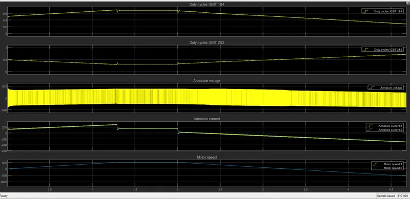
b). Design the parameters in excel sheet is attached.
Conclusion:
- Since we saw the total weights of type of aircrafts.
- Given the difference between the airspeed and ground speed.
- Since we have see the engine power to move it on the ground in the aircraft with the help of tow vehicle.
- Explained how aircraft is pushed to runway when its ready to take off.
- We have Learn about take off power, tyre design, rolling resistance, tyre pressure, brake forces when landing.
- Calculate the Force and power required to push/pull an aircraft bya towing vehicle.
- Design the electric vehicle powertrain with motor rating duty cycle which motor is contrlled using controller and also calculate power, Torque to move the aircraft with the towing vehicle.