Project-1: Powertrain for aircraft in runways
Part A:
1. Search and list out the total weight of various types of aircrafts.
2. Is there any difference between ground speed and air speed?
3. Why is it not recommended to use aircraft engine power to move it on the ground at Airport?
4. How an aircraft is pushed to runway when its ready to take off?
5. Learn about take off power, tyre design, rolling resistance, tyre pressure, brake forces when landing.
Read this from left to right, from detailed to generalized. Boxes on the right sum up the separate items which they run across.
The maximum landing weight is what the manufacturer has certified for landings. Generally, this is MTOW minus some fuel.
Note that every manufacturer has his own standard and might draw the lines between the different weight groups differently. Say, for one the engine quadrant is part of the propulsion system, whereas the other sees it as part of the control system.
The aircraft has:
- Basic Empty Weight (BEW) is the weight of the aircraft "as built" and includes the weight of the structure, power plant, furnishings, installations, systems and other equipment that are considered an integral part of an aircraft before additional operator items are added for operation.
- Dry Operating Wieght (DOW) BEW + Weight of Crew (Pilot + Cabin including their bags) + Pantry
- Operating Weight (OW) DOW + Takeoff fuel (i.e. Ramp Fuel - Taxi fuel)
- Maximum Zero Fuel Weight (MZFW) DOW + Payload (anything put on the aircraft that generates revenue to the company, e.g. passenger, baggage, cargo, mail and fret)
- Maximum Taxi Weight (MTW) MZFW + Ramp fuel
- Maximum Takeoff Weight (MTOW) MZFW + Takeoff fuel, or MTW - Taxi fuel
Airplanes[edit]
MTOW = Maximum take-off weight, MLW = Maximum landing weight, TOR = Take-off run (SL, ISA+15°, MTOW), LR = Landing run (SL, ISA+15°, MLW)
| Type | MTOW [kg] | MLW [tonnes] | TOR [m] | LR [m] | ICAO category | FAA category |
|---|---|---|---|---|---|---|
| Antonov An-225 | 640,000 | 591.7 | 3500 | Heavy | Super | |
| Scaled Composites Model 351 Stratolaunch | 589,670 | 3660 | Heavy | Super | ||
| Airbus A380-800[1][2][3] | 575,000 | 394 | 3100 | 1930 | Heavy | Super |
| Boeing 747-8F | 447,700 | 346.091 | 3100 | 1800 | Heavy | Heavy |
| Boeing 747-8 | 443,613 | 306.175 | 3100 | Heavy | Heavy | |
| Boeing 747-400ER | 412,770 | 295.742 | 3090 | Heavy | Heavy | |
| Antonov An-124-100M | 405,060 | 330 | 2520 | 900 | Heavy | Heavy |
| Boeing 747-400 | 396,900 | 295.742 | 3018 | 2179 | Heavy | Heavy |
| Lockheed C-5 Galaxy[4][5][6] | 381,000 | 288.417 | 2530 | 1494 | Heavy | Heavy |
| Boeing 747-200[7] | 377,840 | 285.700 | 3338 | 2109 | Heavy | Heavy |
| Boeing 747-300[7] | 377,840 | 260.320 | 3222 | 1905 | Heavy | Heavy |
| Airbus A340-500[8] | 371,950 | 240 | 3050 | 2010 | Heavy | Heavy |
| Airbus A340-600[8] | 367,400 | 256 | 3100 | 2100 | Heavy | Heavy |
| Boeing 777F | 347,800 | 260.816 | 2830 | Heavy | Heavy | |
| Boeing 777-300ER | 351,800 | 251.29 | 3100 | Heavy | Heavy | |
| Boeing 777-200LR | 347,450 | 223.168 | 3000 | Heavy | Heavy | |
| Boeing 747-100[7] | 340,200 | 265.300 | Heavy | Heavy | ||
| Airbus A350-1000 | 308,000 | 233.5 | Heavy | Heavy | ||
| Boeing 777-300 | 299,370 | 237.683 | 3380 | Heavy | Heavy | |
| Boeing 777-200ER | 297,550 | 213.00 | 3380 | 1550 | Heavy | Heavy |
| Airbus A340-300[8][9] | 276,700 | 190 | 3000 | 1926 | Heavy | Heavy |
| McDonnell Douglas MD-11 | 273,300 | 185 | 2990 | 1890 | Heavy | Heavy |
| Airbus A350-900 | 270,000 | 175 | 2670 | 1860 | Heavy | Heavy |
| Ilyushin Il-96M | 270,000 | 195.04 | 3115 | 2118 | Heavy | Heavy |
| McDonnell Douglas DC-10 | 256,280 | 183 | 2990 | 1890 | Heavy | Heavy |
| Boeing 787-9[10] | 254,000 | 192.777 | 2900 | Heavy | Heavy | |
| Boeing 787-10[10] | 254,000 | 201.849 | Heavy | Heavy | ||
| Airbus A340-200[8][11] | 253,500 | 181 | 2990 | Heavy | Heavy | |
| Airbus A330-900 | 251,000 | 191 | 3100 | Heavy | Heavy | |
| Ilyushin IL-96-300 | 250,000 | 175 | 2600 | 1980 | Heavy | Heavy |
| Airbus A330-300[12][13] | 242,000 | 185 | 2500 | 1750 | Heavy | Heavy |
| Airbus A330-200[12][13] | 242,000 | 180 | 2220 | 1750 | Heavy | Heavy |
| Lockheed L-1011-500 | 231,300 | 166.92 | 2636 | Heavy | Heavy | |
| Boeing 787-8[10] | 228,000 | 172.365 | 3300 | 1695 | Heavy | Heavy |
| Lockheed L-1011-200 | 211,400 | Heavy | Heavy | |||
| Ilyushin IL-86 | 208,000 | 175 | Heavy | Heavy | ||
| Boeing 767-400ER | 204,000 | 158.758 | 3414 | Heavy | Heavy | |
| Airbus A300-600R[14] | 192,000 | 140 | 2385 | 1555 | Heavy | Heavy |
| Boeing 767-300ER | 187,000 | 136.08 | 2713 | 1676 | Heavy | Heavy |
| Concorde | 185,000 | 111.1 | 3440 | 2220 | Heavy | Heavy |
| Airbus A300-600[14] | 163,000 | 138 | 2324 | 1536 | Heavy | Heavy |
| Boeing 767-300 | 159,000 | 136.078 | 2713 | 1676 | Heavy | Heavy |
| Airbus A310-300[14] | 157,000 | 124 | 2290 | 1490 | Heavy | Heavy |
| Vickers VC10 | 152,000 | 151.9 | Heavy | Heavy | ||
| Boeing 707-320B[15] | 151,000 | 97.5 | Heavy | Heavy | ||
| Boeing 707-320C[15] | 151,000 | 112.1 | Heavy | Heavy | ||
| Douglas DC-8-61 | 147,000 | Heavy | Heavy | |||
| Airbus A310-200[14] | 142,000 | 123 | 1860 | 1480 | Heavy | Heavy |
| Airbus A400M | 141,000 | 122 | 980 | 770 | Heavy | Heavy |
| Douglas DC-8-32 | 140,000 | Heavy | Heavy | |||
| Douglas DC-8-51 | 125,000 | Medium | Large | |||
| Boeing 757-300 | 124,000 | 101.6 | 2550 | 1750 | Medium | Large |
| Boeing 707-120B[15] | 117,000 | 86.3 | Medium | Large | ||
| Boeing 757-200 | 116,000 | 89.9 | 2347 | 1555 | Medium | Large |
| Boeing 720B[16] | 106,000 | 79.5 | Medium | Large | ||
| Boeing 720[16] | 104,000 | 79.5 | Medium | Large | ||
| Tupolev Tu-154M | 104,000 | 80 | Medium | Large | ||
| Tupolev Tu-204SM | 104,000 | 87.5 | 2250 | Medium | Large | |
| Convair 880 | 87,500 | Medium | Large | |||
| Boeing 737-900 | 85,000 | 66.36 | 2500 | 1704 | Medium | Large |
| Boeing 737-900ER | 85,000 | 71.35 | 2804 | 1829 | Medium | Large |
| Boeing 727-200 Advanced[17] | 84,000 | 70.1 | Medium | Large | ||
| Airbus A321-100[18] | 83,000 | 77.8 | 2200 | 1540 | Medium | Large |
| Boeing 737-800 | 79,000 | 65.32 | 2308 | 1634 | Medium | Large |
| Boeing 727-200[17] | 78,000 | 68.1 | Medium | Large | ||
| McDonnell-Douglas MD-83 | 73,000 | 63.28 | Medium | Large | ||
| Boeing 727-100[17] | 72,500 | 62.4 | Medium | Large | ||
| Boeing 727-100C[17] | 72,500 | 62.4 | Medium | Large | ||
| McDonnell-Douglas MD-90-30 | 71,000 | 64.41 | 2165 | 1520 | Medium | Large |
| de Havilland Comet 4 | 70,700 | Medium | Large | |||
| Boeing 737-700 | 70,000 | 58.06 | 1921 | 1415 | Medium | Large |
| Airbus A320-100[18] | 68,000 | 66 | 1955 | 1490 | Medium | Large |
| Boeing 737-400 | 68,000 | 54.9 | 2540 | 1540 | Medium | Large |
| de Havilland Comet 3 | 68,000 | Medium | Large | |||
| Boeing 377 | 67,000 | Medium | Large | |||
| Boeing 737-600 | 66,000 | 54.66 | 1796 | 1340 | Medium | Large |
| Airbus A220-300 | 65,000 | 57.61 | 1890 | 1494 | Medium | Large |
| Hawker Siddeley Trident 2E | 65,000 | Medium | Large | |||
| Airbus A319[18] | 64,000 | 62.5 | 1850 | 1470 | Medium | Large |
| Boeing 737-300 | 63,000 | 51.7 | 1939 | 1396 | Medium | Large |
| Boeing 737-500 | 60,000 | 49.9 | 1832 | 1360 | Medium | Large |
| Airbus A220-100 | 59,000 | 50.80 | 1463 | 1356 | Medium | Large |
| Airbus A318[18] | 59,000 | 57.5 | 1375 | 1340 | Medium | Large |
| Boeing 717-200HGW | 55,000 | 47.174 | 1950 | Medium | Large | |
| Douglas DC-7 | 55,000 | Medium | Large | |||
| de Havilland Comet 2 | 54,000 | Medium | Large | |||
| Boeing 717-200BGW | 50,000 | 46.265 | 1950 | Medium | Large | |
| de Havilland Comet 1 | 50,000 | Medium | Large | |||
| Douglas DC-6A | 48,600 | Medium | Large | |||
| Douglas DC-6B | 48,500 | Medium | Large | |||
| Embraer 190[19] | 48,000 | 43 | 2056 | 1323 | Medium | Large |
| Caravelle III | 46,000 | Medium | Large | |||
| Fokker 100 | 46,000 | 39.95 | 1621 | 1350 | Medium | Large |
| Douglas DC-6 | 44,000 | Medium | Large | |||
| Avro RJ-85 | 42,000 | 36.74 | Medium | Large | ||
| Handley Page Hermes | 39,000 | Medium | Large | |||
| Embraer 175[20] | 37,500 | 32.8 | 2244 | 1304 | Medium | Large |
| Bombardier CRJ900[21] | 36,500 | 33.345 | 1778 | 1596 | Medium | Large |
| Embraer 170[22] | 36,000 | 32.8 | 1644 | 1274 | Medium | Large |
| Bombardier CRJ700 | 33,000 | 30.39 | 1564 | 1478 | Medium | Large |
| Douglas DC-4 | 33,000 | Medium | Large | |||
| Vickers Viscount 800 | 30,400 | Medium | Large | |||
| Bombardier Q400 | 28,000 | 28.01 | 1219 | 1295 | Medium | Large |
| Bombardier CRJ200 | 23,000 | 21.319 | 1918 | 1479 | Medium | Large |
| ATR 72-600 | 22,800 | 22.35 | 1333 | 914 | Medium | Large |
| Saab 2000 | 22,800 | 21.5 | 1300 | Medium | Large | |
| Embraer ERJ 145 | 22,000 | 19.3 | 2270 | 1380 | Medium | Large |
| ATR 42-500 | 18,600 | 18.3 | 1165 | 1126 | Medium | Small |
| Saab 340 | 13,150 | 12.930 | 1300 | 1030 | Medium | Small |
| Embraer 120 Brasilia | 11,500 | 11.25 | 1560 | 1380 | Medium | Small |
| BAe Jetstream 41 | 10,890 | 10.570 | 1493 | 826 | Medium | Small |
| Learjet 75[23] | 9,752 | 8.709 | 1353 | 811 | Medium | Small |
| Pilatus PC-24[24] | 8,300 | 7.665 | 893 | 724 | Medium | Small |
| Embraer Phenom 300[25] | 8,150 | 7.65 | 956 | 677 | Medium | Small |
| Beechcraft 1900D | 7,765 | 7.605 | 1036 | 853 | Medium | Small |
| Cessna Citation CJ4[26] | 7,761 | 7.103 | 1039 | 896 | Medium | Small |
| de Havilland Hercules | 7,000 | Medium | Small | |||
| Embraer Phenom 100 | 4,800 | 4.43 | 975 | 741 | Light | Small |
2. Is there any difference between ground speed and air speed?
Ground speed is defined as the aircraft’s horizontal speed relative to the surface of the Earth, airspeed is defined as its speed relative to the air it is flying in.
Below, I am going to explain the two types of speed in more detail:
> The relationship between airspeed and ground speed is fairly simple. Ground speed is simply the sum of airspeed and wind speed.
> If the aircraft is flying in the same direction as the wind is blowing, the aircraft experiences tailwind, and its ground speed is higher than its airspeed. On the other hand, if the wind is blowing against the direction the aircraft is traveling in, the aircraft experiences headwind, and its ground speed is lower than its airspeed.
> To give you an actual example, imagine an aircraft that cruises at an airspeed of 500 miles per hour that has to cover a ground distance of 2,000 miles.
If there is no wind at all, then both the aircraft’s airspeed and ground speed would be the same 500 miles per hour, and the aircraft would reach its destination in four hours.
If there was a 100 miles per hour headwind – wind blowing against the aircraft’s direction of travel – the aircraft would still be traveling at an airspeed of 500 miles per hour. However, its ground speed would be just 400 miles per hour (100 miles per hour slower than its airspeed). And as such, it would take the aircraft five hours to reach its destinations.
Finally, if there was a 100 miles per hour tailwind – wind blowing in the same direction as the aircraft’s travel – the aircraft would still be traveling at an airspeed of 500 miles per hour, but its ground speed would be 100 miles faster.
And, at 600 miles an hour, the aircraft would reach its destination in just three hours and twenty minutes.
The above is the reason why some flights go “out of their way” to avoid headwinds or catch tailwinds. And, why some flights might appear to be traveling at “supersonic speeds,” even though their airspeed – the speed that would actually matter in determining whether or not the flight truly is supersonic – is subsonic.
>> For pilots, both airspeed and ground speed are very important. While the first of those helps them make sure they are flying fast enough to take off, not to stall, and so on, the second one helps them figure out how long it will take them to get from one place to another.
>> On the other hand, if you are a passenger, you will only need to be concerned about the ground speed as that will tell you how fast are you flying from your origin to your destination – how fast you will be able to get to your meeting, meet your relatives, or do whatever else the reason for your travel might be.
An interactive version of this page is also available.
One of the most confusing concepts for young scientists is the relative velocity between objects. Aerodynamic forces are generated by an object moving through a fluid (liquid or gas). A fixed object in a static fluid does not generate aerodynamic forces. Hot air balloons "lift" because of buoyancy forces and some aircraft like the Harrier use thrust to "lift" the vehicle, but these are not examples of aerodynamic lift. To generate lift, an object must move through the air, or air must move past the object. Aerodynamic lift depends on the square of the velocity between the object and the air. Now things get confusing because not only can the object be moved through the air, but the air itself can move. To properly define the relative velocity, it is necessary to pick a fixed reference point and measure velocities relative to the fixed point. In this slide, the reference point is fixed to the ground, but it could just as easily be fixed to the aircraft itself. It is important to understand the relationships of wind speed to ground speed and airspeed.
Wind Speed
For a reference point picked on the ground, the air moves relative to the reference point at the wind speed. Notice that the wind speed is a vector quantity and has both a magnitude and a direction. Direction is important. A 20 mph wind from the west is different from a 20 mph wind from the east. The wind has components in all three primary directions (north-south, east-west, and up-down). In this figure, we are considering only velocities along the aircraft's flight path. A positive velocity is defined to be in the direction of the aircraft's motion. We are neglecting cross winds, which occur perpendicular to the flight path but parallel to the ground, and updrafts and downdrafts, which occur perpendicular to the ground.
Ground Speed
For a reference point picked on the ground, the aircraft moves relative to the reference point at the ground speed. Ground speed is also a vector quantity so a comparison of the ground speed to the wind speed must be done according to rules for vector comparisons.
Airspeed
The important quantity in the generation of lift is the relative velocity between the object and the air, which is called the airspeed. Airspeed cannot be directly measured from a ground position, but must be computed from the ground speed and the wind speed. Airspeed is the vector difference between the ground speed and the wind speed.
Airspeed = Ground Speed - Wind Speed
On a perfectly still day, the airspeed is equal to the ground speed. But if the wind is blowing in the same direction that the aircraft is moving, the airspeed will be less than the ground speed.
Examples
Suppose we had an airplane that could take off on a windless day at 100 mph (liftoff airspeed is 100 mph). We are at an airport with an east-west runway that is 1 mile long. The wind is blowing 20 mph towards the west and the airplane takes off going east. The wind is blowing towards the aircraft which we call a headwind. Since we have defined a positive velocity to be in the direction of the aircraft's motion, a headwind is a negative velocity. While the plane is sitting still on the runway, it has a ground speed of 0 and an airspeed of 20 mph:
Airspeed = Ground Speed (0) - Wind Speed (-20) = 20 mph
The airplane starts its take off roll and has a constant acceleration a. From Newton's second law of motion, the ground speed V at any time t is:
V = a * t
and the distance d down the runway at any time is:
d = 1/2 * a * t^2
For a fixed length runway, this specifies the time to be used in the velocity equation. Let's assume that at 5000 feet down the runway, the velocity is 80 mph. Then the airspeed is given by
Airspeed = Ground Speed (80) - Wind Speed (-20) = 100 mph
and the airplane begins to fly. Now another pilot, with exactly the same airplane decides to take off to the west. The wind is now in the same direction as the motion and this is called a tailwind. The sign on the wind speed is now positive, not negative as with the headwind. The acceleration along the ground is the same, so at 5000 feet down the runway, the ground speed is again 80 mph. The airspeed is then given by:
Airspeed = Ground Speed (80) - Wind Speed (20) = 60 mph
This airplane doesn't have enough airspeed to fly. It runs off the end of the runway!
3. Why is it not recommended to use aircraft engine power to move it on the ground at Airport?
Hazard
Aircraft systems and construction
HAZARD KNOWLEDGE
Aircraft engines
Engines present many significant hazards to responding fire and rescue services personnel, whether running or isolated. Aircraft engines will contain:
- Fuel pumps and pipelines
- Hydraulic pumps and pipelines
- Oil pumps and pipelines
- Electrical components and high energy ignition systems
- High pressure compressors
- Spinning fans
- Propellers
By their very nature engines create noisy environments (if running), highly heated components and projectile hazards, etc.
Propellers should not be touched. They should be cordoned off and treated as a hazard throughout the incident, as the smallest movement on a propeller can cause fuel to be pumped through the fuel line systems. This may generate ignition sparks, causing the engine to start or turn over.
The hazards posed by exhaust gases and intake air will depend on the size and type of engine involved. Engines that are running should be shut down at the earliest opportunity. Hazard zones in front of engines and to the rear of engines must be established. These hazard areas will differ depending on the aircraft engine size.
Aircraft engines usually come in two types: jet engines or propeller engines. If the engines are running, or have been running, they can present numerous hazards. Engines can generate noise, high temperatures, use oil systems for lubrication, have an electrical supply and have a pressurised fuel system. Aircraft engines are made up of numerous metals, alloys and polymer composites.
If fire and rescue service personnel have to attend an aircraft with engines that are running, the incident commander should ensure that personnel are not put at risk by engine intakes, engine exhausts or propellers that are turning or that have the potential to turn. Intakes are more dangerous than exhausts, as it may be possible for crew members to be ingested through the aircraft engine intake. Safe distances around larger and smaller engines must be considered.
To minimise the risk to personnel of being drawn into engines or being injured as a result of a propeller strike, personnel must not approach the front of any engine that is running or could possibly be running. The recommended safety distance is 10m away from the front and sides of any engine. Engines that are cold and intact should not cause fire and rescue service personnel any problems. Most engines are encased in a cover that has opening cowlings for access to the accessory section; these cowlings have the potential to swing open if disturbed as a result of an accident.
Figure 3: Jet engine hazard areas
Source: International Fire Service Training Association USA
Aircraft fuel systems
All aircraft (with the exception of some gliders) will have a fuel system on board. The size, amount and type of fuel carried will depend on the aircraft, but the hazards will be similar.
One factor related to fuel systems that makes air incidents different from other transport incidents is the volume of fuel that can be involved.
Fuels involved in air transport incidents will range from kerosene, petrol or military fuels, to LPG (in hot air balloons). The principal hazards from fuels in aircrafts are:
- Pressurised fuel lines
- Fuel remaining within the fuselage and aircraft fuel tanks
- Varying degrees of flammability depending on the type of fuel
- Extreme radiated heat
- Escaping fuel creating running fuel fires and pool fires
- Pools of fuel not on fire
- Jettisoned fuel tanks
- Flammable atmospheres surrounding the incident
- Environmental impact
Hydraulic fluid systems
Hydraulic fluid systems will be located on all passenger aircraft and on some general aviation aircraft. The systems will be pressurised (in excess of 200 bars) and although the fluid itself is generally fire resistant, escaping hydraulic fluid can become atomised with the resultant fine mist spray being easily ignited.
Liquid oxygen systems
Two principal types of pressurised oxygen systems are found on board commercial aircraft:
- Compressed oxygen systems
- Liquid oxygen systems
The systems will be under pressure and present a significant hazard if involved in fire.
RADAR systems
RADAR systems with differing wavelengths and strengths may be fitted to some aircraft. Some systems may have transmitting devices in the nose cone or side pods, and some may have externally mounted dishes or scanners. Following a crash, inbuilt safety systems may have automatically disarmed such devices, although crews should not initially approach aircraft that are suspected to contain RADAR systems, until it has been confirmed that the system has been isolated.
Radioactive materials
Radioactive materials may be used in some elements of aircraft construction and may also be present in electrical and electronic equipment installed on some aircraft. Radioactive substances may also be found in aircraft targeting systems and, if damaged, they can leak very small amounts of radioactive material. The probability of coming into contact with radioactive materials at military aircraft incidents is small and crews undertaking firefighting and rescue operations should be adequately protected by their personal protective equipment (PPE) and respiratory protective equipment (RPE).
Hydraulic/cable systems.
Due to the nature of aircraft construction and the systems required for flight, pressurised systems and cables will be running through the cabin, albeit behind interior furnishings. Crews should be mindful of any damage sustained to either the interior or exterior of the aircraft, as they could be exposed to hydraulics or moving surfaces.
Older aircraft have cables under tension. These cables run from the flight deck to the control surfaces such as the rudder, elevators and flaps. If these surfaces are moved by either the flight deck crew, or possibly through actuation by external personnel, these cables will move internally.
In the majority of aircraft, the auxiliary power unit (APU) is normally situated in the tail of the aircraft, and oil and fuel lines have to pass through the aircraft.
Where the interior of the cabin has been damaged these cables will form a significant hazard from entanglement.
Cargo deck
Access is normally made through large cargo bays situated beneath the passenger deck or at the rear of military cargo aircraft. Conditions can be cramped as most aircraft use unit load devices. These lightweight containers are used to maximise the space in the aircraft hold.
Hazards inside a cargo hold include:
- Operating cargo doors. Seek advice from flight crew, aircraft engineers or ground handling crew
- Heavy luggage or cargo falling or tipping over
- Unidentified cargo in a unit loading device or in the shipper's packaging
- Slips, trip and falls due to the mechanisms used to move unit loading devices on the cargo deck floor
- Access/egress
- On-board fire suppression systems
If the incident occurs on an aerodrome then the incident commander should liaise with the aerodrome rescue and firefighting service (RFFS), and with aircraft engineers or flight deck crew. All of these agencies should be able to assist the incident commander with tactical plans and decision making.
If the incident occurs away from the aerodrome, then the incident commander should liaise with the flight deck crew, if possible, and attempt to gain additional information from specialist advisers if necessary.
4. How an aircraft is pushed to runway when its ready to take off?
1. Parking the plane
2. Hooking up the plane
3. Connecting the air-con
4. De-planing
5. Unloading the luggage and cargo
6. Stocking up with food
7. Cleaning the toilets
8. Refueling
9. Pushback
10. Boarding and take-off
ONE THING YOU almost never see when an airplane lands is a blowout. Think about that: Again and again, the tires hit tarmac at 170 miles per hour and bear the weight of a modest office building. And they nail it. Every time.
Aircraft tires are amazing when you think about it. The typical airliner tire can handle a 38-ton load. It can meet the ground 500 times before needing a re-tread, a refresh it can take on seven times in its life.
A Boeing 777 uses 14 tires, Airbus' A380 carries 22, and the enormous Antonov An-225 demands 32. The key to their remarkable durability is maximizing the air pressure, says Lee Bartholomew, lead test engineer for Michelin Aircraft Tires. The high-flying rubber is typically inflated to 200 psi, roughly six times what you put in an automobile tire, and the tires on an F-16 fighter are pumped to 320 psi. “It's really pressurized air that's so strong,” he says.
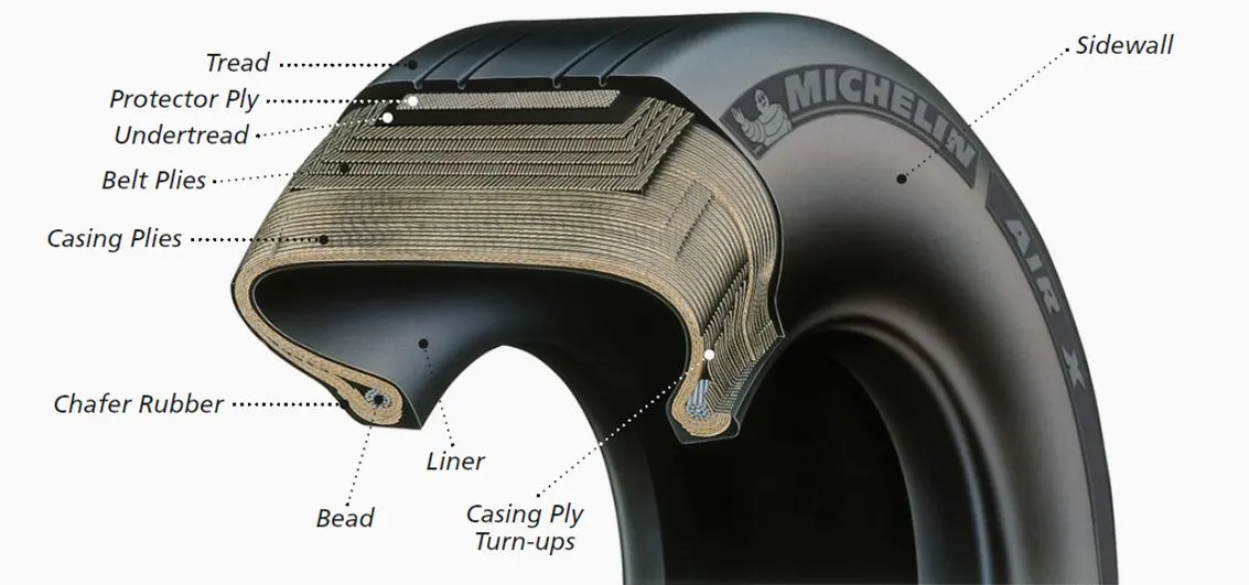
The tires themselves aren't terribly large--- a Boeing 737 rides on 27x7.75 R15 rubber. In English, that means it is 27 inches in diameter, 7.75 inches wide, and wrapped around a 15-inch wheel. The sidewalls aren't terribly thick, and the strength of the tire lies in the cords embedded below the tread, Bartholomew says. They're typically nylon, and more recently a variety known as aramid. Each layer of the casing contributes to its load bearing and air pressure resisting capabilities. Of course, tires can fail, especially when under-inflated or overloaded. Treads can come off and casings can blow out.
PART-B ``
6.Pulling an Airplane
Force required to pull an air plane.
The force to move an airplane on an absolute flat runway with no wind at constant low speed is equal to the rolling resistance between the plane and the tarmac.
The rolling resistance for the air plane can be calculated as
Fr = c mr ag (1)
where
Fr = rolling resistance (N, lbf)
c = rolling resistance coefficient
mr = rolling mass (kg, lbm)
ag = acceleration of gravity (9.81 m/s2)
Example - Force required to pull an airplane at constant low speed on tarmac
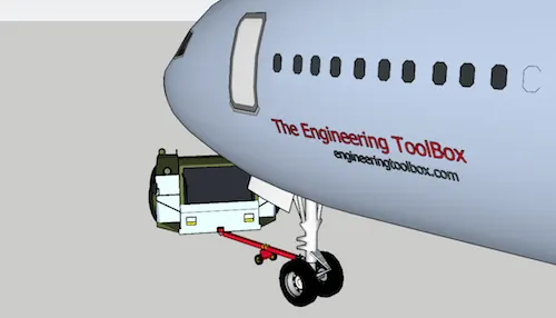
If the mass of a plane is 40000 kg and the rolling coefficient between the aircraft wheel and the tarmac is 0.02 - the force required to overcome the rolling resistance can be calculated as
Fr = 0.02 (40000 kg) (9.81 m/s2)
= 7848 N
This force can be delivered by a pulling truck or - as occasionally seen - by a number of pulling people. Enough weight for the pullers are required to create friction forces against the tarmac that equals the plane rolling resistance.
The friction force for the puller can be calculated to
Ff = μ W
= μ mf ag (2)
where
Ff = frictional force (N, lb)
μ = friction coefficient
W = weight (N, lbf)
mf = friction mass (kg)
Example - Required Mass for Pulling Truck
The friction coefficient between a pulling truck rubber wheels and dry tarmac is 0.9. Since pulling trucks are connected to air crafts nose wheels close to tarmac we simplify the calculation of required truck mass to
mf = (7848 N) / (0.9 (9.81 m/s2))
= 889 kg
Example - Air Craft Pulled by People
When persons participates in aircraft pulling there is normally an offset between the rope connected to the air craft nose wheel and the tarmac. It is common for persons to bend over with the rope over the shoulder or holding it in the hands.
The horizontal friction force between the persons shoes and the tarmac must be equal or larger than the air plane rolling resistance. The minimum required vertical force - or minimum weight of the people - depends on the bending angle as illustrated in the vector diagram below.
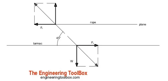
If they bend over 45o - the vertical force or weight equals to the horizontal force. With rubber shoes and the same friction coefficient as above for the truck the weight of the people should be 889 kg. With an average weight of 80 kg/person - the number of persons can be calculated to
n = (889 kg) / (80 kg/person)
= 11.1
= 12
With a more realistic bending angle 60o - the minimum vertical force or weight can be calculated as
W = tan(60o) (7848 N)
= 13593 N
The minimum mass of people to achieve this weight can be calculated as
mf = W / ag
= (13593 N) / (9.81 m/s2)
= 1386 kg
With an average weight of 80 kg/person - the minimum number of persons can be calculated to
n = (1386 kg) (80 kg/person)
= 17.3
= 1
6.B.
2.3. EV Powertrain Modeling and Simulation
EV powertrain modeling and simulation begins with the determination of key design
specifications as detailed in Table 1, adapted from the spec sheet of a Chevrolet Bolt EV.
These specs are then used in an equation-based model of an EV using MATLAB/Simulink,
and the modeling results are then validated using a real-world vehicle performance tested
on a chassis dynamometer.
Table 1. Vehicle Specification for Chevrolet Bolt EV.
Description Value
Initial Acceleration (0–60 mph) 7.5 s
Curb weight 1616.15 kg
Motor power 200 hp/150 kW
Motor torque 266 lb.ft/360 Nm
Final drive ratio 7.05:1
Energy efficiency 300 Wh/mile
Battery capacity 53 kWh
Top speed 93 mph
Aerodynamic drag coefficient 0.308
2.4. Glider Model
The equation-based modeling approach in Simulink involves the representation of
each vehicle component or subsystem as a series of equation blocks connected to each
other through signals that are calculated and updated at each time step. Figure 4 is an
overview of the equation-based model in Simulink to meet the EV specifications previously
described. The glider model represents the point mass model of the vehicle dynamics
previously described. It sums up the forces acting on vehicle body represented by a point
mass, as described in Equations (1)–(5). Table 2 is a summary of parameters used for
the calculation of vehicle dynamics and determining the vehicle speed at each timestep.
Figure 5 is a closer look at the glider model subsystem within the Simulink model where
Equations (1)–(5) are implemented by taking in an input of tractive force and subtracting
the summation of the road load forces to get the inertial force, which is converted into an
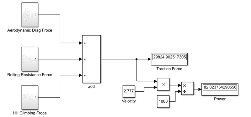
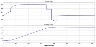
7. A. Design an electric powertrain with type of motor, it’s power rating, and energy requirement to fulfill aircraft towing application in Simulink. Estimate the duty cycle range to control the aircraft speed from zero to highest. Make all required assumptions. Prepare a table of assumed parameters. Draw a block diagram of powertrain.
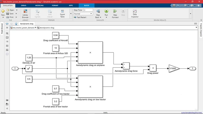
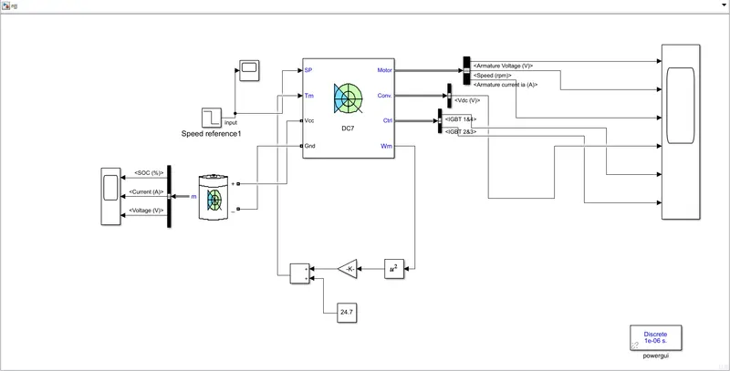
resultant graph: