Week-7 Challenge: DC Motor Control
Speed Control of a DC Motor Using BJT H-Bridge Copy Command
This example shows the simulation of an H-bridge used to generate a chopped voltage and to control the speed of a DC motor.
Gilbert Sybille (Hydro-Quebec)
Description
The Bipolar Junction Transistor (BJT) when used for power switching applications, operates as an IGBT. When it is conducting (BJT operating in the saturated region), a forward voltage Vf is developed between collector and emitter (in the range of 1 V). Therefore, the IGBT block can be used to model the BJT device.
The IGBT block does not simulate the gate current controlling the BJT or IGBT. The switch is controlled by a Simulink® signal (1/0). The DC motor uses the preset model (5 HP 24V 1750 rpm). It simulates a fan type load (where Load torque is proportional to square of speed). The armature mean voltage can be varied from 0 to 240 V when the duty cycle (specified in the Pulse Generator block) is varied from 0 to 100%.
The H-bridge consists of four BJT/Diode pairs (BJT simulated by IGBT models). Two transistors are switched simultaneously: Q1 and Q4 or Q2 and Q3. When Q1 and Q4 are fired, a positive voltage is applied to the motor and diodes D2-D3 operate as free-wheeling diodes when Q1 and Q4 are switched off. When Q2 and Q3 are fired, a negative voltage is applied to the motor and diodes D1-D4 operate as free-wheeling diodes when Q2 and Q3 are switched off.
Simulation
The motor starts in the positive direction with a duty cycle of 75% (mean DC voltage of 180V). At t= 0.5 sec., the armature voltage is suddenly reversed and the motor runs in the negative direction.
'Scope' shows motor speed, armature current and load torque and 'Currents' shows currents flowing in BJT Q3 and diode D3.
A direct current (DC) motor is the oldest type of electrical motor that has gained widespread use in a variety of electronic devices and equipment. DC motors have different arrangements and operation peculiarities.
The common feature and the essential condition of all DC motors is the generation of a variable magnetic field that provides their non-stop operation. In an alternating current (AC) motor, a magnetic field changes polarity on its own.
A DC motor has some significant advantages, and one of them is the simplicity of its control system. Here, we’ll tell you how a DC motor controller works and how you can use it. In addition, we’ll share our personal experience and brief you on the design and challenges that you can meet while building your own controller.
In this article, we have focused mainly on brushed DC (BDC) motor controllers. To learn more about a BLDC motor controller, its design, and working principles, you can check a related article on our blog.
What Is a DC Motor Controller?
The intended use of a motor controller is to manage the performance of an electrical motor. Irrespective of the motor type, this electronic device can fulfill the following functions:
- start/stop the motor;
- change the rotation direction;
- control the speed and torque;
- provide overload protection;
- prevent electrical faults.
The specifics of a DC motor controller depend on the motor type (brushed, brushless, stepper) and functionality of the device that uses this motor. For example, an electric vehicle DC motor controller for a brushless DC (BLDC) motor has different design and working principles compared to an industrial DC motor controller of a brushed motor.
The two core components of any DC motor are a stator and an armature, or rotor. There can also be other components that perform critical functions. Thus, a brushed DC motor comprises the following units:
a stator with windings or permanent magnets;
an armature, or rotor with windings;
a commutator, or collector with brushes connecting the armature with a DC power supply.
The current flowing through the armature gives rise to the electromagnetic field that makes it rotate. As the armature rotates, the similar poles of the magnetic fields created around the stator and rotor repel each other and provide a unidirectional motion.
As soon as the opposite poles meet, the commutator switches the current supplied to the armature. This creates the reverse polarity of the magnetic field, and the armature keeps rotating.

A controller of a brushed DC motor manages the speed and torque of the motor by regulating the current and voltage injected into it. The major design and working principles of BDC motor controllers can differ between their types.
Types of DC Motor Controllers
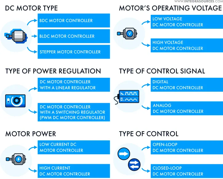
There are different types of DC motor controllers along with the principles of their classification. The infographic below shows this variety.
DC Motor Type
First, controllers vary according to the type of DC motor. For example, unlike a brushed DC motor, a brushless DC (BLDC) motor has an electronic commutator without brushes. It has a rotor with permanent magnets and a stator with windings.
A brushless DC motor controller uses sensors to specify the rotor’s position. It switches the current in the windings with the help of transistors. In our article dedicated to a BLDC motor controller, we provide a detailed description of its working principles and design features.
A stepper motor belongs to the group of brushless DC motors, but its distinguishing feature is that it rotates in stages or steps. After each step, the rotor stops at a certain angle. It allows the device powered by this motor to shift and fix positions with high precision. A stepper motor controller provides current in pulses, energizing poles of the stator and making the rotor move.
The other classifications are typical of almost any electrical motor’s controller. Let’s briefly go over them through the example of a brushed DC motor controller.
Type of Power Regulation
A BDC motor controller regulates the speed and torque by changing the power supplied to the motor. This can be achieved with the help of either a linear or switching voltage regulator. It can be a part of a controller or a separate system.
The basic idea of a linear regulator is to provide stable output voltage. It keeps its magnitude constant, irrespective of the input voltage supplied by a power source. A switching regulator uses the pulse-width modulation (PWM) method.
A PWM DC motor controller makes it possible to supply voltage in pulses, changing its duty cycle (the ratio of the pulse to the pulse period). Thus, you can regulate the speed of the motor by adjusting various duty cycles. A switching regulator has higher efficiency and less power loss., and PWM is widely used in speed controller design for DC motors.
Motor Power
Motor power relies on the current supplied by the power source. Thus, a low-power BDC motor needs a low current controller and vice versa. A high current DC motor controller typically uses a switching regulator.
Motor’s Operating Voltage
Depending on the voltage necessary for the motor’s operation, you can choose a low or high voltage controller. A switching regulator works well for controllers with a wide operating voltage range. A linear regulator better suits a low voltage DC motor controller because the excessive input voltage may cause power loss and even thermal overload.
Type of Control Signal
Controllers are classified into digital and analog versions. The main difference between a digital DC motor controller and its analog variant is that the former comprises microcontroller (MCU) based hardware and firmware.
Type of Control
Some DC motor controller types can receive feedback from the motors, detect errors, and correct them, bringing the values into line with the setpoints. They are called closed-loop or feedback controllers.
Alternatively, an open-loop or non-feedback controller cannot affect the situation, even if a failure occurs, as it will not detect it. You can find such controllers in simple systems that don’t need automatic control.
Open-loop and closed-loop systems are fundamental concepts of control theory. Depending on the requirements or complexity of the electronic device, you can implement a control system either with or without feedback. For example, a stepper motor can operate with an open-loop controller. A servo DC motor controller, used for accurate positioning in high-performance applications, is a closed-loop system.
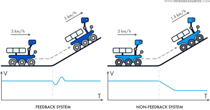
The picture above shows examples of closed-loop and open-loop control systems. In the first case, the robot’s motor controller receives feedback and regulates the speed in accordance with the landscape conditions. In the case of the non-feedback system, the motor controller gets no feedback. So, the robot’s speed decreases as it reaches a plateau.
Application Area of DC Motors and Controllers
DC motors may find use in different devices and systems depending on their characteristics. Thus, stepper and servo motors power machines that require precision positioning such as:
- robots;
- printers;
- cameras;
- CNC machines.
In addition to closed-loop control, advanced DC servo motors with a variable speed DC motor controller show high performance and reliability in complex industrial applications.
The absence of brushes, which are wear-prone parts, makes BLDC motors more durable. Apart from that, the electronic commutator doesn’t make sparks and reduces electromagnetic interference (EMI). So these motors are widely applied in electric vehicles, heating, and ventilation systems because of their reliability. You can learn more about the construction and application of brushless motors in our article on a BLDC motor controller.
Brushed DC motors have been in use for about two hundred years. Although more recent technologies have partially replaced them, they are still popular in different industries and applications.
BDC motors may have a very simple design and are easy to control (some of them may not even need a controller). This is a cost-effective solution that can perfectly fit low voltage devices powered by lithium-ion batteries, including robotics and consumer electronics.
Building an autonomous robotic lawn mower, we installed a reversible DC motor controller with a PWM switching regulator for a brushed DC motor chosen by the customer. The idea was to develop a low power consumption and budget-friendly system.
The robot could easily move in any direction, avoid obstacles, make stops, and move again immediately. We achieved this by using a pulse width modulation DC motor controller that regulated the speed and rotational direction of the motor.
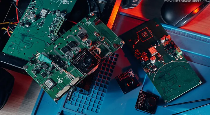
Accessibility and simple implementation of BDC motors and their controllers make them a suitable solution for a number of projects. In this article, we’d like to share our own experience in the design and implementation of a brush DC motor controller. You’ll also learn about challenges you can meet if you decide to build it yourself.
BDC Motor Controller Circuit Design
A traditional BDC motor controller circuit is an H-bridge. This is an electronic circuit with four open/close switches that supply positive and negative voltage by turns. By closing high-side and low-side switches in a diagonal pattern, the motor rotates in one direction. The rotational direction will change as soon as these switches are open and the opposite switches are closed.
If you need a motor with a unidirectional rotation, you can build a BDC motor controller using a simpler circuit with only one open/close switch. Choosing a transistor switch, make sure it meets the required parameters of the motor, for example, the maximum current. Otherwise, the transistor will burn out.
Compliance with the system requirements is the basic principle you should follow while selecting components for your DC motor controller schematic. This relates to an MCU, gate drivers necessary to control the transistors, and other components.
You can use either an integrated circuit (IC) or discrete components. From a developer’s point of view, a DC motor controller IC is a simpler and more convenient solution. With a discrete circuit, it will take you the time and effort to assemble and solder the components. The design of an integrated circuit, however, is quite expensive, and it can earn its keep only in case of mass production.
An integrated H-bridge driver is a circuit with built-in power transistors. Despite the simplicity and reliability of its design, the gate driver IC is intended for low-voltage and low-power applications. Additionally, such gate drivers are not interchangeable. If they become discontinued, you’ll have to redesign the schematic together with the printed circuit board.
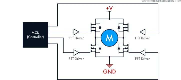
BDC motor controller circuit design depends on the type of signal, power regulation, control system, and other features. You can choose among various options based on your technical specifications and budget limits.
Cooperating with Basicmicro Motion Control, we created brushed BDC motor controllers for DIY robot kits. It was a variable DC motor controller with a switching voltage regulator. An important feature of the controller is that it can use both an open-loop and a closed-loop system.
With the help of our 2-channel BDC motor controllers, users can control robots remotely via a wireless communication module. Our team provided electronic design and embedded software development for the project.
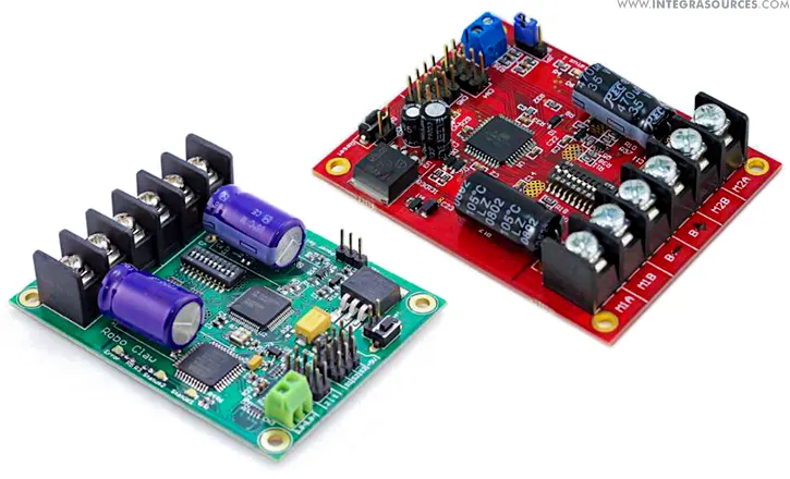
We used an H-bridge circuit for the controllers. As it was a discrete circuit, Integra’s engineers had to choose MCUs and gate drivers with separate semiconductor switches. We opted for power MOSFETs that fit well with low voltage controllers because of the following advantages:
- a fast switching speed;
- a low price;
- easy maintenance;
- high efficiency.
Designing a high current DC motor controller schematic, we used an IGBT that combines features of power MOSFETs and bipolar switches. It provides a high level of current and is well suited for complex power electronics systems.
Another option that you can choose for your project is a GaN transistor made of hard and extremely durable semiconductor material. It can resist high temperatures and operates at very high frequency and voltage ranges. GaNs are used in high-power electronics, industrial, and aerospace applications. However, their production cost is still very high, so it will raise the price of your circuit design as well.
As a result, we designed a programmable DC motor controller with several operation modes. It could be controlled with the help of analog and digital signals. In addition, it could use a closed-loop system and read data from a digital quadrature encoder installed on the rotor.
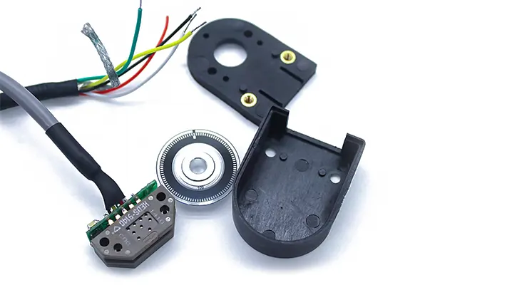
The encoder converted the rotational speed and direction of the motor into digital signals recognized by the controller. When changes occurred, the controller adjusted the control actions as necessary.
To provide safe operation of the motor, our developers implemented overcurrent, overvoltage, and overtemperature protection systems. To achieve this, we added the corresponding sensors in the DC motor controller design.
Challenges of Making a BDC Motor Controller
Building a BDC motor controller can be quite simple, but it still involves some challenges. These can relate to both circuit design and firmware development. Let’s take a look at the things that may need your special attention.
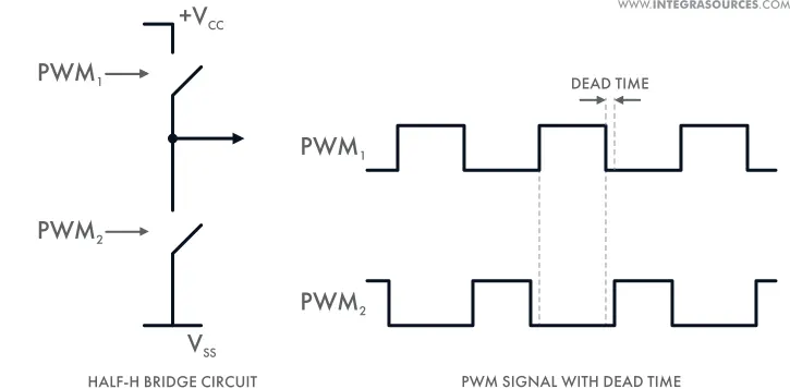
As we have mentioned earlier, switches are open and closed diagonally in an H-bridge circuit, but these actions can’t go on simultaneously. There will always be a moment when all the transistors are open. It may lead to voltage and power loss, or even short-out if the opposite upper and lower switches are in the on position.
To avoid this situation, you can introduce dead time. This is a short period of time when all switches of an H-bridge circuit are closed. Using dead time, you can make sure the upper switch will open only after the lower switch is closed.
PWM frequency (the number of pulse periods per second) is an important parameter that you should adjust in a proper way. The lower the frequency, the higher the power loss, and vice versa. However, in case the PWM frequency is too high, the MCU may have problems with generating PWM signals of the required value. In addition, the very high frequency may lead to the malfunction of the gate driver and transistor switches as they may not be compatible with it.
When writing firmware, remember to set up the correct PWM frequency to ensure the smooth operation of your motor controller.
As you deal with a brushed DC motor, you might come across the problem of excessive electromagnetic interference. Generated because of the constant switching of the commutator, it affects neighboring electronic components. To reduce it, you could implement different filters that protect the wires from EMI.
Designing BDC motor controllers for our robotics project, we had to meet some challenges.
The basic customer requirements included the wide operating voltage and current ranges. At that moment, there were no suitable off-the-shelf integrated gate drivers or GaN semiconductors. In addition, this range was too low for an IGBT. Thus, we had to search for a solution among discrete power MOSFETs.
Our team considered several circuit options and chose a standard gate driver with external MOSFETs. By implementing this discrete component solution, we simplified the schematic design and cut development costs. As a result, Integra’s engineers achieved stable operation of the BDC motor controller in the range of 6 up to 24 volts and up to 25 amps.
As soon as we used a discrete circuit, the responsibility for the major functions of the BDC motor controller rested with the MCU. Our engineers implemented algorithms that generated PWM signals with the required duty cycles and dead time.
Implementing a feedback control system, we faced a problem with the microcontroller that couldn’t process the encoder signal outputs. So we had to add a CPLD that could read high frequency signals. If you are planning to build a brushed DC motor controller with feedback, make sure your MCU can provide this opportunity.
Conclusion
A brushed DC motor is one of the most common types of electrical motors. It is widely used in consumer electronics, robotics, low-power industrial and automotive applications. A BDC motor, as well as its control system, has a simple construction and easy implementation.
With some viable alternatives available now, it’s becoming hard for a BDC motor to stay competitive in high-power electronics. Besides, its controller has brushes, and you will have to replace these wearable parts with time. However, with proper use and maintenance, it can provide an efficient and long-lasting performance.
If you need a controller for a BDC motor, you can use an off-the-shelf device that fully meets your requirements. Or you can build your own solution with a tailor-made circuit design and custom firmware. Electronics and semiconductor manufacturers offer a rich selection of hardware and software components that you can use in your project. For example, in building a BDC motor controller circuit for the robotic lawn mower, we used STM32F4, which is part of the STM32 ecosystem for motor control.
Entrusting your project to an external engineering team, make sure they have relevant skills and expertise. An experienced developer will consider each nuance and figure out how to design a DC motor controller for your particular project.
Integra has provided schematic design, PCB layout, and firmware development services for 150+ projects, including power converters, voltage regulators, and motor controls. During our 7+ years of experience, we have worked with a wide range of microcontrollers and semiconductor devices. We have created circuits for applications that operate over a full range of current, voltage, and switching frequency.
Description
The Two-Quadrant Chopper block represents a two-quadrant controlled chopper for converting a fixed DC input to a variable DC output. The block contains two switching devices. Options for the type of switching devices are:
-
GTO — Gate turn-off thyristor. For information about the I-V characteristic of the device, see GTO.
-
Ideal semiconductor switch — For information about the I-V characteristic of the device, see Ideal Semiconductor Switch.
-
IGBT — Insulated-gate bipolar transistor. For information about the I-V characteristic of the device, see IGBT (Ideal, Switching).
-
MOSFET — N-channel metal-oxide-semiconductor field-effect transistor. For information about the I-V characteristic of the device, see MOSFET (Ideal, Switching).
-
Thyristor — For information about the I-V characteristic of the device, see Thyristor (Piecewise Linear).
-
Averaged Switch — Semiconductor switch with an anti-parallel diode. The control signal port, G, accepts values in the
[0,1]interval. When the value at port G is equal to0or1, the averaged switch is either fully opened or fully closed, and it behaves similarly to the Ideal Semiconductor Switch block with an anti-parallel diode. When the value at port G is between0and1, the averaged switch is partly opened. You can then average the PWM signal over a specified period. This allows for undersampling of the model or using modulation waveforms instead of PWM signals.
Specify Chopper Quadrants
You can choose the quadrants where the Two-Quadrant Chopper operates. To select the quadrants, set the Modeling option parameter to either:
-
First and second quadrant. The figures show the equivalent circuit and the operation for the first- and second- quadrant model. -
First and fourth quadrant. The figures show the equivalent circuit and the operation for the first- and fourth- quadrant model.
Protection
The block contains an integral protection diode for each switching device. The integral diode protects the semiconductor device by providing a conduction path for reverse current. An inductive load can produce a high reverse-voltage spike when the semiconductor device suddenly switches off the voltage supply to the load.
To configure the internal protection diode block, use the Diode parameters. This table shows how to set the Model dynamics parameter based on your goals.
| Goals | Value to Select | Integral Protection Diode |
|---|---|---|
| Prioritize simulation speed. | Diode with no dynamics |
The Diode block |
| Prioritize model fidelity by precisely specifying reverse-mode charge dynamics. | Diode with charge dynamics |
The dynamic model of the Diode block |
You can also include a snubber circuit for each switching device. Snubber circuits contain a series-connected resistor and capacitor. They protect switching devices against high voltages that inductive loads produce when the device turns off the voltage supply to the load. Snubber circuits also prevent excessive rates of current change when a switching device turns on.
To include and configure a snubber circuit for each switching device, use the Snubbers parameters.
Gate Control
To connect Simulink® gate-control voltage signals to the gate ports of the internal switching devices:
-
Convert each voltage signal using a Simulink-PS Converter block.
-
Multiplex the converted gate signals into a single vector using a Two-Pulse Gate Multiplexer block.
-
Connect the vector signal to the G port
3.Construction, Working & Applications of BLDC (Brushless DC Motor)
Brushless DC motors (BLDC) have been a much focused area for numerous motor manufacturers as these motors are increasingly the preferred choice in many applications, especially in the field of motor control technology. BLDC motors are superior to brushed DC motors in many ways, such as ability to operate at high speeds, high efficiency, and better heat dissipation.
They are an indispensable part of modern drive technology, most commonly employed for actuating drives, machine tools, electric propulsion, robotics, computer peripherals and also for electrical power generation. With the development of sensorless technology besides digital control, these motors become so effective in terms of total system cost, size and reliability.
What is a Brushless DC motor (BLDC)?
A brushless DC motor (known as BLDC) is a permanent magnet synchronous electric motor which is driven by direct current (DC) electricity and it accomplishes electronically controlled commutation system (commutation is the process of producing rotational torque in the motor by changing phase currents through it at appropriate times) instead of a mechanically commutation system. BLDC motors are also referred as trapezoidal permanent magnet motors.
Unlike conventional brushed type DC motor, wherein the brushes make the mechanical contact with commutator on the rotor so as to form an electric path between a DC electric source and rotor armature windings, BLDC motor employs electrical commutation with permanent magnet rotor and a stator with a sequence of coils. In this motor, permanent magnet (or field poles) rotates and current carrying conductors are fixed.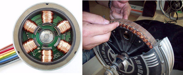
The armature coils are switched electronically by transistors or silicon controlled rectifiers at the correct rotor position in such a way that armature field is in space quadrature with the rotor field poles. Hence the force acting on the rotor causes it to rotate. Hall sensors or rotary encoders are most commonly used to sense the position of the rotor and are positioned around the stator. The rotor position feedback from the sensor helps to determine when to switch the armature current.
This electronic commutation arrangement eliminates the commutator arrangement and brushes in a DC motor and hence more reliable and less noisy operation is achieved. Due to the absence of brushes BLDC motors are capable to run at high speeds. The efficiency of BLDC motors is typically 85 to 90 percent, whereas as brushed type DC motors are 75 to 80 percent efficient. There are wide varieties of BLDC motors available ranging from small power range to fractional horsepower, integral horsepower and large power ranges.
Construction of BLDC Motor
BLDC motors can be constructed in different physical configurations. Depending on the stator windings, these can be configured as single-phase, two-phase, or three-phase motors. However, three-phase BLDC motors with permanent magnet rotor are most commonly used.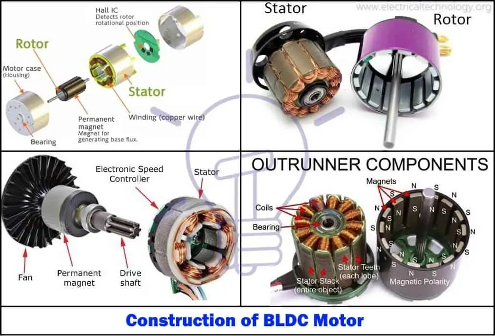
The construction of this motor has many similarities of three phase induction motor as well as conventional DC motor. This motor has stator and rotor parts as like all other motors.
Stator of a BLDC motor made up of stacked steel laminations to carry the windings. These windings are placed in slots which are axially cut along the inner periphery of the stator. These windings can be arranged in either star or delta. However, most BLDC motors have three phase star connected stator.
Each winding is constructed with numerous interconnected coils, where one or more coils are placed in each slot. In order to form an even number of poles, each of these windings is distributed over the stator periphery.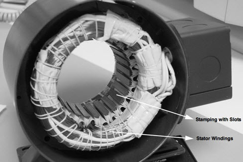
The stator must be chosen with the correct rating of the voltage depending on the power supply capability. For robotics, automotive and small actuating applications, 48 V or less voltage BLDC motors are preferred. For industrial applications and automation systems, 100 V or higher rating motors are used.
- You may also read: What is a Solenoid and Solenoid Magnetic Field
Rotor
BLDC motor incorporates a permanent magnet in the rotor. The number of poles in the rotor can vary from 2 to 8 pole pairs with alternate south and north poles depending on the application requirement. In order to achieve maximum torque in the motor, the flux density of the material should be high. A proper magnetic material for the rotor is needed to produce required magnetic field density.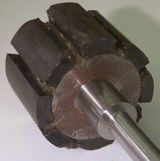
Ferrite magnets are inexpensive, however they have a low flux density for a given volume. Rare earth alloy magnets are commonly used for new designs. Some of these alloys are Samarium Cobalt (SmCo), Neodymium (Nd), and Ferrite and Boron (NdFeB). The rotor can be constructed with different core configurations such as the circular core with permanent magnet on the periphery, circular core with rectangular magnets, etc.
- Related Post: What is Motor Efficiency & How to improve it?
Hall Sensors
Hall sensor provides the information to synchronize stator armature excitation with rotor position. Since the commutation of BLDC motor is controlled electronically, the stator windings should be energized in sequence in order to rotate the motor. Before energizing a particular stator winding, acknowledgment of rotor position is necessary. So the Hall Effect sensor embedded in stator senses the rotor position.
Most BLDC motors incorporate three Hall sensors which are embedded into the stator. Each sensor generates Low and High signals whenever the rotor poles pass near to it. The exact commutation sequence to the stator winding can be determined based on the combination of these three sensor’s response.
- Related Post Why Electric Motors rated in kW instead of kVA?
Working Principle and Operation of BLDC Motor
BLDC motor works on the principle similar to that of a conventional DC motor, i.e., the Lorentz force law which states that whenever a current carrying conductor placed in a magnetic field it experiences a force. As a consequence of reaction force, the magnet will experience an equal and opposite force. In case BLDC motor, the current carrying conductor is stationary while the permanent magnet moves
When the stator coils are electrically switched by a supply source, it becomes electromagnet and starts producing the uniform field in the air gap. Though the source of supply is DC, switching makes to generate an AC voltage waveform with trapezoidal shape. Due to the force of interaction between electromagnet stator and permanent magnet rotor, the rotor continues to rotate.
Consider the figure below in which motor stator is excited based on different switching states. With the switching of windings as High and Low signals, corresponding winding energized as North and South poles. The permanent magnet rotor with North and South poles align with stator poles causing motor to rotate.
Observe that motor produces torque because of the development of attraction forces (when North-South or South-North alignment) and repulsion forces (when North-North or South-South alignment). By this way motor moves in a clockwise direction.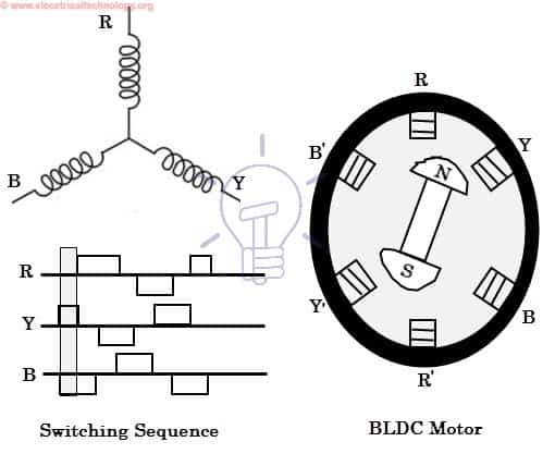
Here, one might get a question that how we know which stator coil should be energized and when to do. This is because; the motor continuous rotation depends on the switching sequence around the coils. As discussed above that Hall sensors give shaft position feedback to the electronic controller unit.
Based on this signal from sensor, the controller decides particular coils to energize. Hall-effect sensors generate Low and High level signals whenever rotor poles pass near to it. These signals determine the position of the shaft.
Brushless DC Motor Drive
As described above that the electronic controller circuit energizes appropriate motor winding by turning transistor or other solid state switches to rotate the motor continuously. The figure below shows the simple BLDC motor drive circuit which consists of MOSFET bridge (also called as inverter bridge), electronic controller, hall effect sensor and BLDC motor.
Here, Hall-effect sensors are used for position and speed feedback. The electronic controller can be a microcontroller unit or microprocessor or DSP processor or FPGA unit or any other controller. This controller receives these signals, processes them and sends the control signals to the MOSFET driver circuit.
In addition to the switching for a rated speed of the motor, additional electronic circuitry changes the motor speed based on required application. These speed control units are generally implemented with PID controllers to have precise control. It is also possible to produce four-quadrant operation from the motor whilst maintaining good efficiency throughout the speed variations using modern drives.
Advantages of BLDC Motor
BLDC motor has several advantages over conventional DC motors and some of these are
- It has no mechanical commutator and associated problems
- High efficiency due to the use of permanent magnet rotor
- High speed of operation even in loaded and unloaded conditions due to the absence of brushes that limits the speed
- Smaller motor geometry and lighter in weight than both brushed type DC and induction AC motors
- Long life as no inspection and maintenance is required for commutator system
- Higher dynamic response due to low inertia and carrying windings in the stator
- Less electromagnetic interference
- Quite operation (or low noise) due to absence of brushes
Disadvantages of Brushless Motor
- These motors are costly
- Electronic controller required control this motor is expensive
- Not much availability of many integrated electronic control solutions, especially for tiny BLDC motors
- Requires complex drive circuitry
- Need of additional sensors
Applications of Brushless DC Motors (BLDC)
Brushless DC Motors (BLDC) are used for a wide variety of application requirements such as varying loads, constant loads and positioning applications in the fields of industrial control, automotive, aviation, automation systems, health care equipments, etc. Some specific applications of BLDC motors are
- Computer hard drives and DVD/CD players
- Electric vehicles, hybrid vehicles, and electric bicycles
- Industrial robots, CNC machine tools, and simple belt driven systems
- Washing machines, compressors and dryers
- Fans, pumps and blowers