Project-1: Powertrain for aircraft in runways
Part A:
1. Search and list out the total weight of various types of aircrafts.
Aircrafts can be classified based on the means by which they are propelled in the air and/or kept afloat:
Aircraft that are made such that they themselves are ligher than atmospheric air (w.r.t. density), which make them float, are of the 'lighter than air' type and those which are not are the 'heavier than air type'. Lighter than air aircrafts are for example, 'Balloons', 'Airships' and 'Kite balloons'.
Heavier than air balloons can be further classified as follows,
- Engine driven
- Airplane
- Amphibian
- Land (itself includes commercial aircrafts, passenger planes, jets, light sport aircrafts etc.)
- Sea
- Rotary wing
- Helicopter
- Gyro plane
- Airplane
- Without engine
- Glider & Sail plane
- Kite
(The names of the types of aircrafts above are self-explanatory)
To list out the weights of aircrafts of each type in detail could be tedious (especially because there would be a large variation of weights in each type). Since this is not the main purpose of this study, weights of only a few types are evaluated to get an idea of the aircraft weights-
Land airplanes could range from a gross take-off weight of 575 tonnes (Airbus A380-800, a passenger aircraft) to as low as 1100 kg (Cessna 172R) ref.
Helicopters could weigh typically from a gross take weight of 56 tonnes (Mil Mi-26 "Halo", a Russian transport helicopter) to as low as 275 kg (Mosquito Aviation XE) ref.
An Airship could weigh anywhere between 5 to 10 tonnes
2. Is there any difference between ground speed and air speed?
The ground speed of an aircraft is the velocity of the aircraft in relation to a fixed point on the ground, while the air speed is the difference between it's ground speed and that the wind velocity of the space it is travelling in.
Significance of these characterisation of the aircraft speed- The ground speed would give an estimate of the distance travelled by the aircraft and could be used, for example, to compute the time of arrival at destination. The air velocity gives the aircraft's relative motion in space and couldbe useful in getting an estimate of, for example, the power required for air-craft propulsion.
3. Why is it not recommended to use aircraft engine power to move it on the ground at Airport?
Using the engine power to move the aircraft on ground could result in the following issues,
i. Damage the structures in the vicinity of the air-craft due to the jet-blast that occurs after turning on the engine.
ii. Sound of the engine could be irritating for people in close proximity.
iii. Engine could consume more fuel than by moving the aircraft using a pushback vehicle.
iv. The suction force caused by engine could suck in a debris/sand in ground area.
4. How an aircraft is pushed to runway when its ready to take off?
Due to the reasons mentioned above, an aircraft is pushed to the runway using a 'pushback truck'. Generally, a pushback truck is connected to the front wheel of the aircraft using a 'tow-bar'. Further, a 'by-pass pin' is used to cut-off the control of the wheel from the pilot. The aircraft is then pushed by the truck until it reaches a location where is it safe to to use start and use the engine and proceed for take-off. This process is involves co-ordination between the pilot and a few airport personnel for navigation.
5. Learn about take off power, tyre design, rolling resistance, tyre pressure, brake forces when landing.
Take off power:
The take-off of an aircraft is accomplished by making the lift forces on it more than it's weight. In this process, the air-craft is set in motion so as to induce a Benoulli's effect to assist the engine power, resulting in a sustained take-off.
Take off power- This is the amount of power required from the engine at take-off i.e. the point at which the aircraft becomes airborne.
The take-off power is very demanding on the engine and full engine power could be required. The power used has an impact on the engine life and fuel efficiency. Hence, it is preferable to reduce the required engine power which could be achieved for example by having a long runway (although this would result in a longer time for take-off) or having a drier runway.
Tyre design:
Although the tyres of an aircraft would be used only for a short period when compared to the length of it's journey, their design requires special considerations as compared with an on-ground vehicle like a car. For example,
- They have to support the weight of the air-craft on the ground which are usually very high.
- They need to provide good traction during on-ground commute especially for braking during the landing operation.
- They need to be able to absorb a the shock during a landing operation.
Rolling-resistance:
The rolling resistance is the force opposing the thrust on the air-craft by virtue of the friction between the wheels and the ground. As in a regular vehicle, it can be given by `F_{rr} = \mu_{rr}mg` where, `\mu_{rr}` is the coefficient of rolling resistance, `m` is the mass of the plane and `g` is the gravitational acceleration. The rolling-resistance is of special significance in air-crafts owing to it's high mass!
Tyre pressure:
Aircrafts are required to be able to handle high pressures, failing which could be hazardous for example in the following ways,
- deflation of tyres could lead to a higher rolling resistance which could impede the plane from smooth braking which would be critical during landing operation
- an explosion of the tyre(s) could occur for example due to impact during landing which would be hazardous.
Generally speaking, passenger aircrafts are operated at around the pressures 200-300 psi. Some tests are done which show the tyres are able to withstand pressures of upto 800psi before exploding.
Brake forces when landing:
In general, passenger and commercial aircraft land at speeds of around 150-200 mph and braking is applied to bring plane to a halt. On can imagine that this job could be skillful and challenging for the pilot, especially when there is a rainy and a cross wind environment on the ground. To assist the braking force which is enforced at the tyres, spoilers on the plane are engaged to provide reverse thrust. This also helps in avoiding the wheels to skid on the ground.
Part B:
6. A. With necessary assumptions, calculate the force and power required to push / pull an aircraft by a towing vehicle.
For this exercise, we consider a Boeing 747 as the aircraft and a 'Little big tug company T80 model' as the pushback vehicle. their specifications are taken from the links link1 and link2 respectively. Note that, for the computation of required force and power, the forces on both the aircraft and the tug need to be considered. We make the computations for an acceleration requirement of going from 0 to 10kmph in 300s and a then holding a steady state velocity of 10kmph.
The computations are done using the excel-sheet we had designed in an earlier assignment as shown below (also the whole file is attached),
| *Grey cells indicate assumed values | |||
| Vehicle power requirement calculations | |||
| Boeing 747 | Pushback vehicle (Little big tug company T80) | ||
| Rolling resistance calculations | |||
| Kerb weight (kg) | 363000.0000 | 72000.0000 | |
| Payload (kg) | 0.0000 | 0.0000 | |
| Coefficient of rolling resistance | 0.0130 | 0.0130 | |
| Gravitational acceleration (m/s2) | 9.8000 | 9.8000 | |
| Rolling resistance force (N) | 46246.2000 | 9172.8000 | |
| Air drag calculations | |||
| Air density (kg/m3) | 1.2500 | 1.2500 | |
| Width (m) | 2.7500 | ||
| Height (m) | 2.3800 | ||
| Frontal area (m2) | 180.0000 | 6.5450 | |
| Drag coefficient | 0.0300 | 0.0300 | |
| Speed (kmph) | 10.0000 | 10.0000 | |
| Air drag force (N) | 26.0417 | 0.9469 | |
| Acceleration force calculations | |||
| Time to reach final velocity (s) | 300.0000 | 300.0000 | |
| Acceleration (m/s2) | 0.0093 | 0.0093 | |
| Acceleration force (N) | 3361.1111 | 666.6667 | |
| Total force required (kN) | 49.6334 | 9.8404 | 59.4738 |
| Power required (ideal) (kW) | 165.2049 |
Result-
As seen from the calculations above,
the required force would be 59.47 kN
the required power would be 165.20 k
B. Develop the model for the calculated force and power using Simulink.
A simulink model for making the computations mentioned above is developed as shown below (also file attached),
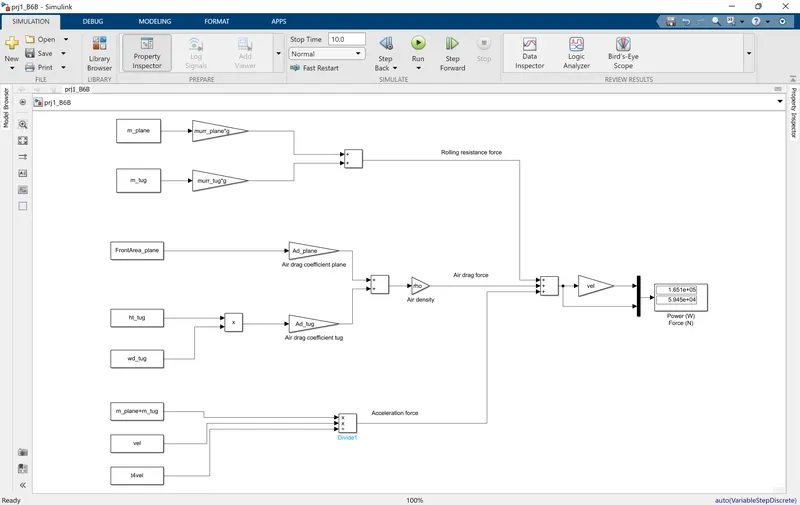
It is seen that the results are consistent with what was obtained in the previous question.
7. A. Design an electric powertrain with type of motor, it’s power rating, and energy requirement to fulfill aircraft towing application in Simulink. Estimate the duty cycle range to control the aircraft speed from zero to highest. Make all required assumptions. Prepare a table of assumed parameters. Draw a block diagram of powertrain.
(Hint :DC7 Block)
For this question, we will use the same type of aircraft and pushback tug that we used in the previous question. So from the result of the previous question, we know the power and force requirement rating as 165.20 kW and 59.47 kN respectively. We will now compute these requirements taking into account the losses in the motor and transmission,
Assuming motor efficiency of `\eta_{m} =`90% and a transmission efficiency of `\eta_{tx} =`85%, we have the actual power requirement as,
`P_{actual} = P_{ideal}/{\eta_{m}\eta_{tx}} = 165.20/(0.9*0.85) = 215.95 kW`
Now suppose we require to use the tug for 10 hrs before it could be re-charged, the energy requirement of the battery would be,
`E_{bat} = P_{actual}*10 = 2159.54 kWh`
For this, we could choose a motor of rating `P_m = 300kW` with an energy rating of 2500 kWh. With this, the required maximum duty cycle (DC) could be computer as,
DC = `P_{actual}/P_{m} = 215.95/300 = 71.98 %`.
Furthermore, assuming the wheel radius of the tug to be `r = 0.5m` and a gear ratio of `G = 8`, we have the torque requirement from the motor as,
`T_m = {F*r}/{G*\eta_{tx}} = 59.47*0.5/{8*0.85} = 4.37 kNm`.
These computations are done using excel and are taulated as shown below,
| Total force required (kN) | 49.6334 | 9.8404 | 59.4738 |
| Power required (ideal) (kW) | 165.2049 | ||
| Motor efficiency (%) | 90.0000 | ||
| Transmission efficiency (%) | 85.0000 | ||
| Power required (actual) (kW) | 215.9541 | ||
| Required operation time (h) | 10.0000 | ||
| Energy required (actual) (kWh) | 2159.5413 | ||
| Motor power (kW) | 300.0000 | ||
| Max duty cycle required (%) | 71.9847 | ||
| Tug wheel radius (m) | 0.5000 | ||
| Gear ratio (-) | 8.0000 | ||
| Required torque at wheel (kNm) | 29.7369 | ||
| Required torque by motor (kNm) | 4.3731 |
A block diagram of the EV power train for the above design is shown below,
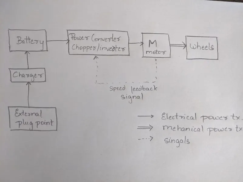 .
.
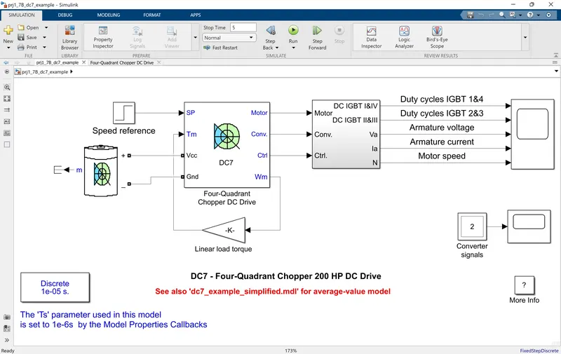
Now, we will try to simulate the above design in Simulink using the DC7 Block as suggested in the question:
Note that, unfortunately, the DC7 block does not directly allow us the freedom to implement values of our desgined parameters. However, we will use the model to illustrate the working of our design although with different parameters.
Below, the designed model is seen (simulink file attached). Here,
- we replace the 3 phase power supply and the rectifier with a battery to supply the DC voltage. This represents a battery in the our pushback tug.
- The speed reference is given such that it represents the pushback process of the aircraft which assume to involve a gradual rise in velocity until a constant speed is reached.
- The rating of the battery is set to suit that of the motor.
- The DC motor consists a DC motor driven by an H-bridge. This motor actually in a no-load condition and with only the motor shaft with a certain inertia and damping as a load. We take this take to represent the aircraft, controlled by a speed reference.
With this setting, the results obtained are shown below.
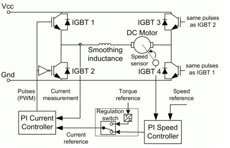
Below, we see the design of the DC drive used in the model which will help us understand the results.
Results:
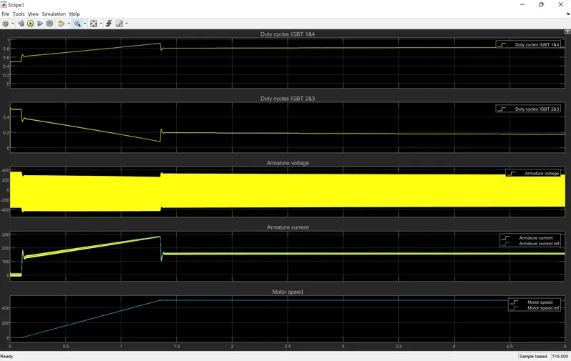
Here, we see that the motor is able to track the given reference speed successfully.
At the required steady state speed, a duty-cycle of around 80% is applied to PWM signal controlling the Armature current which turns on the IGBT switches 1 and 4 during the ON state resulting resulting in forward torque generation. However, we notice that a higher level of duty-cycle is applied during the transition state to accomodate the acceleration forces acting on the load.
When the PWM signal is in the OFF state, the IGBT switches 3 and 2 are ON resulting in reverse voltage. Hence there is switching of the voltage seen at every period of the PWM signal. However, as is quite evident, the average value of the voltage in positive and hence resulting in forward motion of the aircraft.
B. Also, Design the parameters in excel sheet.
The computations done above are also designed in an excel (included in excel file sumbitted for PartB: 6A)