Project-1: Powertrain for aircraft in runways
Objective -
To list out the total weight of various types of aircrafts.
Theory -
When looking at different aircraft's specifications, there are several different weights of the aircraft mentioned. A brief description about these is below:
- Manufacturer's empty weight (MEW) -
- Also called Manufacturer's Weight Empty (MWE) or Licensed Empty Weight
- It is the weight of the aircraft "as built" and includes the weight of the structure, power plant, furnishings, installations, systems and other equipment that are considered an integral part of an aircraft.
- This excludes any baggage, passengers, or usable fuel
- Zero-fuel weight (ZFW) -
- This is the total weight of the airplane and all its contents (including unusable fuel), but excluding the total weight of the usable fuel on board.
- As a flight progresses and fuel is consumed, the total weight of the airplane reduces, but the ZFW remains constant.
- Maximum zero fuel weight (MZFW) is the maximum weight allowed before usable fuel and other specified usable agents (engine injection fluid, and other consumable propulsion agents) are loaded.
- Operating empty weight (OEW) -
- It is the basic weight of an aircraft including the crew, all fluids necessary for operation such as engine oil, engine coolant, water, unusable fuel and all operator items and equipment required for flight but excluding usable fuel and the payload.
- Roughly equivalent to basic empty weight on light aircraft.
- Payload -
- It is the carrying capacity of an aircraft.
- It includes cargo, people, extra fuel.
- In the case of a commercial airliner, it may refer only to revenue-generating cargo or paying passengers.
- Maximum takeoff weight (MTOW) -
- This is the maximum weight at which the pilot of the aircraft is allowed to attempt to take off.
- Regulated takeoff weight (RTOW) -
- Depending on different factors (e.g. flap setting, altitude, air temperature, length of runway), RTOW or maximum permissible takeoff weight varies for each takeoff.
- It can never be higher than MTOW.
- Maximum landing weight (MLW) -
- This maximum weight at which an aircraft is permitted to land.
- The following image depicts takeoff weight components
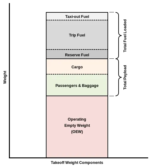
- Maximum ramp weight (MRW) -
- also called maximum taxi weight (MTW).
- It is the maximum weight authorized for maneuvering (taxiing or towing) an aircraft on the ground.
- Aircraft gross weight -
- It is the total aircraft weight at any moment during the flight or ground operation.
- This decreases during flight due to fuel and oil consumption.
The components weight in different weights of aircraft is given below
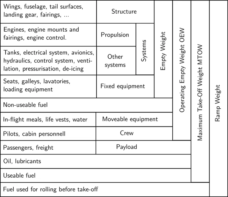
Some examples of different aircrafts with their weights -
| Aircraft | Empty Weight | Maximum Fuel Weight | Maximum Cargo Weight |
Maximum Gross Takeoff Weight |
|
Airbus A380-800 |
611,000 lbs 277,000 kg |
560,000 lbs 254,000 kg |
185,000 lbs 84,000 kg |
1,268,000 lbs 575,000 kg |
|
Airbus A340-500 |
370,000 lbs 168,000 kg |
386,300 lbs 175,000 kg |
119,000 lbs 54,000 kg |
820,000 lbs 372,000 kg |
|
Bombardier CRJ900 |
48,160 lbs 21,850 kg |
19,600 lbs 8,900 kg |
6,075 lbs 2,760 kg |
80,500 lbs 36,500 kg |
|
Sirrus SR22 |
2,250 lbs 1,000 kg |
485 lb 220 kg |
950 lbs 430 kg |
3,600 lb 1,630 kg |
|
Boeing 737-900 |
98,500 lbs 44,700 kg |
53,100 lbs 24,000 kg |
44,600 lbs 20,200 kg |
187,000 lbs 85,000 kg |
---------------------------------------------------------------------------------------------------------------------------------------------------------
Objective -
To discuss the difference between ground speed and air speed.
Theory -
Ground Speed -
- Ground speed is the horizontal speed of an aircraft relative to the Earth’s surface.
- It is vital for accurate navigation that the pilot has an estimate of the ground speed that will be achieved during each leg of a flight.
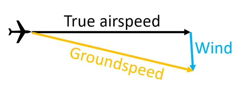
- Ground speed can be determined by the vector sum of the aircraft's true airspeed and the current wind speed and direction.
Wind Speed -
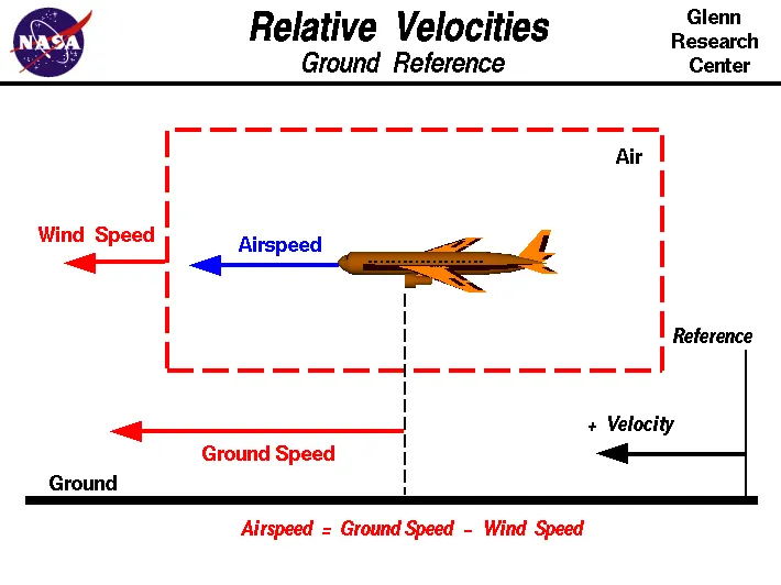
- For a reference point picked on the ground, the air moves relative to the reference point at the wind speed.
- Wind speed is a vector quantity.
Air Speed -
- In aviation, airspeed is the speed of an aircraft relative to the air.
- Among the common conventions for qualifying airspeed are :
- Indicated airspeed ("IAS"), what is read on an airspeed gauge connected to a Pitot-static system.
- Calibrated airspeed ("CAS"), indicated airspeed adjusted for pitot system position and installation error.
- Equivalent airspeed ("EAS"), calibrated airspeed adjusted for compressibility effects.
- True airspeed ("TAS"), equivalent airspeed adjusted for air density, and is also the speed of the aircraft through the air in which it is flying.
- Airspeed cannot be directly measured from a ground position, but must be computed from the ground speed and the wind speed.
- Airspeed is the vector difference between the ground speed and the wind speed.
Difference between Air Speed and Ground Speed -
| Ground Speed |
Air Speed |
|
|
------------------------------------------------------------------------------------------------------------------------------------------------------
Objective -
To discuss about why is it not recommended to use aircraft engine power to move it on the ground at Airport.
Theory -
Taxiing -
- Taxiing (rarely spelled taxying) is the movement of an aircraft on the ground, under its own power, in contrast to towing or pushback where the aircraft is moved by a tug.
- An airplane uses taxiways to taxi from one place on an airport to another.
- The term "taxiing" is not used for the accelerating run along a runway prior to takeoff, or the decelerating run immediately after landing, which are called the takeoff roll and landing rollout, respectively.
Propulsion -
- The thrust to propel the aircraft forward comes from its propellers or jet engines.
- Reverse thrust for backing up can be generated by thrust reversers.
- Most aircraft, however, are not designed to back up on their own and must be pushed back either by hand or by using an aircraft tug.
Reverse Thrust -
- Reverse thrust, also known as thrust reversal, involves diverting the thrust of an aircraft's engines to decelerate the plane.
- When reverse thrust is active, it changes the direction of airflow emanating from the engine to help slow the aircraft down.
- When an aircraft is in operation, its engines provide forward thrust by blasting out air in the opposite direction to the plane's travel direction.
- With enough thrust, the aircraft generates lift, which allows it to take off and remain airborne.
- Reverse thrust does exactly what its name would suggest - reversing the direction of airflow to provide an opposing, decelerating force on the plane's direction of travel.
- Reverse thrust is rarely used to reverse an aircraft from the gate.
Why Aircraft Engine Power is not used on the ground -
- Sometimes it leads to loss of control of the aircraft by those persons occupying the pilot seats in the flight deck.
- Unintended movement of the aircraft.
- Damage can occur to the aircraft itself, other aircraft nearby or to airside structures.
- It can create debris and suck objects into the engine.
- There is a risk of injury to ground support personnel who may be in relatively close proximity to the aircraft.
These are the reasons as aircraft engine power is not used to move the aircraft on ground.
---------------------------------------------------------------------------------------------------------------------------------------------------
Objective -
To discuss about how an aircraft is pushed to runway when its ready to take off.
Theory -
Towing -
- Movement of large aircraft about the airport, flight line, and hangar is usually accomplished by towing with a tow tractor (sometimes called a “tug”).
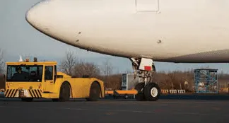
- In the case of small aircraft, some moving is accomplished by hand pushing on the correct areas of the aircraft.
- Aircraft may also be taxied about the flight line but usually only by certain qualified personnel.
- Some types of tow bars available for general use can be used for many types of towing operations.
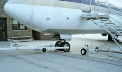
- These bars are designed with sufficient tensile strength to pull most aircraft, but are not intended to be subjected to torsional or twisting loads.
- Many have small wheels that permit them to be drawn behind the towing vehicle going to or from an aircraft.
Process of moving the aircraft to runways -
- To move the aircraft a tug is used.
- When the tug is attached to the aircraft, inspect all the engaging devices for damage or malfunction before moving the aircraft.
- Move the aircraft to the taxiway assigned to the aircraft.
- This taxiway will lead the aircraft to the runaway.
-----------------------------------------------------------------------------------------------------------------------------------------------------
Objective -
To learn about take off power, tyre design, rolling resistance, tyre pressure, brake forces during landing.
Theory -
Take-off Power -
- Takeoff is the phase of flight in which an aerospace vehicle leaves the ground and becomes airborne.
- For aircraft traveling vertically, this is known as liftoff.
- For light aircraft, usually full power is used during takeoff.
- Large transport category (airliner) aircraft may use a reduced power for takeoff, where less than full power is applied in order to prolong engine life, reduce maintenance costs and reduce noise emissions.
- The nose is raised to a nominal 5°–15° nose up pitch attitude to increase lift from the wings and effect liftoff.
- Power is controlled in such a way that it can cover 35 feet screen height plays in the take-off.
- Takeoff performance can be predicted by using a simple measure of acceleration of aircraft among the runway based on force equilibrium.
- The take-off power is calculated as
Take off Power = Force * Displacement = (m * dv/dt)*l = (T - D - F) * l
- where,
- l is the length of the runway
- T, D and F are forces acting which are
- T is Thrust of propulsion system
- D is the Aerodynamic Force
- F is the rolling resistance force.
Tyre Design -
- An aircraft tyre is designed to withstand extremely heavy loads while landing, take off, taxing, and parking.
- The number of wheels required for aircraft increases with the weight of the aircraft, as the weight of the aeroplane needs to be distributed more evenly.
- Aircraft tire tread patterns are designed to facilitate stability in high crosswind conditions, to channel water away to prevent hydroplaning, and for braking effect.
Design and Construction of Aircraft Tyre -
Objective -
To learn about take off power, tyre design, rolling resistance, tyre pressure, brake forces during landing.
Theory -
Take-off Power -
- Takeoff is the phase of flight in which an aerospace vehicle leaves the ground and becomes airborne.
- For aircraft traveling vertically, this is known as liftoff.
- For light aircraft, usually full power is used during takeoff.
- Large transport category (airliner) aircraft may use a reduced power for takeoff, where less than full power is applied in order to prolong engine life, reduce maintenance costs and reduce noise emissions.
- The nose is raised to a nominal 5°–15° nose up pitch attitude to increase lift from the wings and effect liftoff.
- Power is controlled in such a way that it can cover 35 feet screen height plays in the take-off.
- Takeoff performance can be predicted by using a simple measure of acceleration of aircraft among the runway based on force equilibrium.
- The take-off power is calculated as
Take off Power = Force * Displacement = (m * dv/dt)*l = (T - D - F) * l
- where,
- l is the length of the runway
- T, D and F are forces acting which are
- T is Thrust of propulsion system
- D is the Aerodynamic Force
- F is the rolling resistance force.
Tyre Design -
- An aircraft tyre is designed to withstand extremely heavy loads while landing, take off, taxing, and parking.
- The number of wheels required for aircraft increases with the weight of the aircraft, as the weight of the aeroplane needs to be distributed more evenly.
- Aircraft tire tread patterns are designed to facilitate stability in high crosswind conditions, to channel water away to prevent hydroplaning, and for braking effect.
- An aircraft tyre absorbs the high impact loads of landing, and also it’s operating at high speeds for a short time when required.
Design and Construction of Aircraft Tyre -
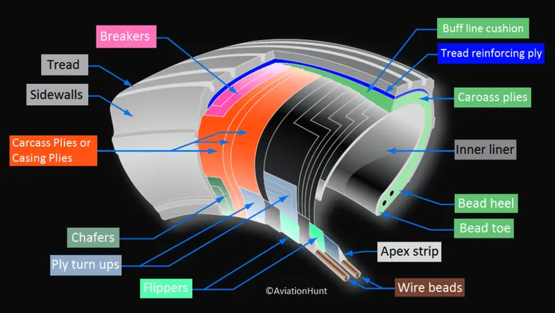
- Carcass plies are used to form the tire, sometimes called as casing plies.
- An aircraft tyre is constructed for the purpose
- They support the weight of an aircraft while it is on the ground.
- It also provides the necessary traction for braking and stopping of an aeroplane.
- Tyre also helps to absorb the shock of landing and provide cushioning the roughness of takeoff, roll-out, and taxi operations.
- Retreading - Retreading is methods of restoring a worn tyre by renewing the tread area or by renewing the tread area plus one or both sidewalls. Repairs are included in the tyre retreading process.
- Load Rating – Load rating is the maximum permissible load at a specified inflation pressure.
- Ply Rating – Ply Rating is used to identify the maximum recommended load rating and inflation pressure for a specified tyre. It is an index of tyre strength.
- Speed Rating – The speed rating is the maximum takeoff speed to which the tyre has been tested.
- Skid Depth – Skid depth is the distance between the tread surface and the deepest groove as measured in the mould.
- Tubeless tyres are more advantageous over tube-type.
- Aircraft tyres are manufactured with tread rubber with conducting compounds to permit earthing of static charges.
- Chine tyre used on the nose wheel of aircraft, specially fuselage-mounted jet engines. It diverts runway water away from the engine inlets.
- Chines are also called deflectors.
Rolling Resistance Force -
- Rolling resistance, sometimes called rolling friction or rolling drag, is the force resisting the motion when a body (such as a ball, tire, or wheel) rolls on a surface.
- It is mainly caused by non-elastic effects; that is, not all the energy needed for deformation (or movement) of the wheel, roadbed, etc., is recovered when the pressure is removed.
- Rolling resistance is often expressed as a coefficient times the normal force.
- This coefficient of rolling resistance is generally much smaller than the coefficient of sliding friction.
- The "rolling resistance coefficient" is defined by the following equation -
`F_(rr) = mu_(rr) * m *g`
- where, Frr is the rolling resistance force
- `mu_(rr)` is the coefficient of the rolling resistance.
- m is the mass of the aircraft.
- g is the acceleration due to the gravity.
Tyre Pressure -
- The tyre of an aircraft have to withstand very high amounts of pressure, while taking off, landing, taxiing and towing.
- While landing, in the first moments after a plane touches down, the tires are skidding, not rolling.
- The airplane essentially drags them down the runway until their rotational velocity matches the velocity of the plane.
- Thats why they smoke upon landing.
- Aircraft tyres are filled with nitrogen instead of air as it has a low moisture content so it doesn’t freeze and it will not support combustion.
Brake Force During Landing -
- Bringing at aircraft down to the runway from 37,000 feet is only part of the challenge.
- It’s not over until the aircraft is safely parked at its gate.
- In order to do this, pilots have a number of systems available to slow the aircraft down.
- Electric Brakes -
- The brake system is controlled by the pilots pressing the tops of the rudder pedals under their feet, demanding the rate of braking which they require.
- This sends an electronic signal to the Left and Right Brake System Control Units (BSCUs).
- These then send signals to the four Electronic Brake Actuator Controllers (EBAC) which control the rate of braking on the wheels.
- The brake disks themselves are made up of two parts.
- Firstly, there are the rotors. These are connected to the wheel by drive tabs.
- As these drive tabs are in contact with the inside of the wheel, they spin at the same speed.
- The second part of the disks are the stators.
- These sit around each rotor and are fixed in place and thus don’t move.
- As the wheel turns, the rotors spin round inside the stators.
- When the brakes are applied, the four EBAs apply pressure to the first stator.
- This in turn squeezes the stationary stators up against the spinning rotors and it’s this friction which slows the wheel down.
- Anti-skid Protection -
- When landing on slippery runways, there’s a chance that the wheels may start to skid as the brakes are applied.
- To stop this from happening and to maintain maximum effective braking, each wheel has anti-skid protection.
- Using a variety of sources to determine the aircraft speed, the brake units know how fast the wheels should be spinning.
- If that speed drops significantly, it’s because the current brake pressure on that wheel is too great and the wheel is just skidding over the surface.
- In this situation, the anti-skid system automatically reduces the braking on that wheel to a point where the skid stops before reapplying the pressure.
- All this is done in a fraction of a second.
- Autobrake -
- To help us get the braking underway as soon as touch down, we have the autobrake system.
- This provides automatic braking at a preselected rate as soon as the aircraft senses that it is on the ground.
- It also provides full braking pressure in the case of a rejected takeoff if the speed is above 85 knots (98 mph).
- Spoilers -
- These are the large panels on the top of the wings raise up on touch down.
- They literally spoil the airflow over the wing.
- This dumps any remaining lift the wings are generating, allowing the wheels to take all the weight and achieve maximum efficiency from the brakes.
- Reverse Thrust -
- The final part of the braking process comes from reverse thrust.
- Just after touch down two levers are pulled on top of the thrust levers to engage the reverse thrust.
- This causes blockers inside the engine to deploy and a door in the side of the engine to slide backward. The air which normally leaves the engine out the back is deflected forward by the blockers and out through the door.
-------------------------------------------------------------------------------------------------------------------------------------------------------
Objective -
- To calculate the force and power required to push / pull an aircraft by a towing vehicle with necessary assumptions.
- To develop the model for the calculated force and power using Simulink.
Calculations -
Lets take the example of Airbus a380.
Total mass of Aircraft (including payload) = 664000 kg
Coefficient of Rolling Friction = 0.0022
Drag coefficient = 0.02
Air density = 1.125 kg/`m^3`
Frontal area = 350 `m^2`
Velocity = 8 km/hr = 2.22 m/s
Let Mass of the towing vehicle = 20000 kg
Rolling Resistance force is given by
`F_(rr) = mu_(rr)*m*g` = 0.0022 * (664000 + 20000) * 9.81 = 14762.088 N
`F_(rr) =` 14.762 kN
Aerodynamic Drag Force (`F_(ad)`) is given by
`F_(ad) = 0.5*C_d * rho *A*v^2` = 0.5 * 0.02 * 350 * 1.125 * 2.22 * 2.22
`F_(ad)` = 19.40 N
As the vehicle is moving at very low speed, acceleration force is neglected and due to the flat runways hill climbing force is also neglected.
Total Force = `F_(rr) + F_(ad)` = 14.78 kN
Power Required = `F_t * v` = 14.78 * 2.22 = 32.81 kW
The minimum power required by the towing vehicle is 32.81 kW.
Simulink Model -
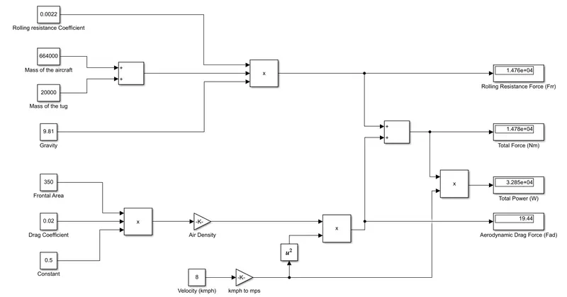
Blocks Used -
The blocks used for creating this simulink model are -
- Constant - To provide the variable value.
- Sum - To add different constant values.
- Product - To multiply two or more input signals.
- Gain - To multiply the input signal by given gain value.
- Square - To square the value of input signal.
- Display - To show the end results.
Explanation -
- To calculate the rolling resistance force,
- the coefficient value, mass and gravity acceleration is provided by constant block.
- A product block is used to multiply these three values and the result is shown using display block.
- To calculate the aerodynamic drag force,
- The variables value are provided using constant blocks.
- To squaring the velocity, a square block is used.
- The values are multiplied according to formula of aerodynamic drag force.
- The result of this is shown using a display.
- The sum of both the force is shown by using display after adding them using sum block.
- The power required is shown in display after multiplying the velocity and sum of both forces.
Results -
- Total force required is 14.78 kN.
- Total Power required is 32.81 kW.
------------------------------------------------------------------------------------------------------------------------------------------------------
Objective -
- To draw a block diagram of powertrain.
- To estimate the duty cycle range to control the aircraft speed from zero to highest. Make all required assumptions.
- To prepare a table of assumed parameters.
- To design an electric powertrain with type of motor, it’s power rating, and energy requirement to fulfill aircraft towing application in Simulink.
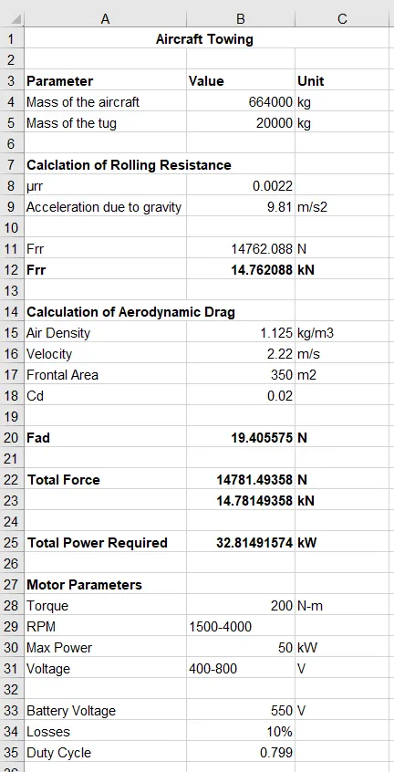
- To design the parameters in excel sheet.
Theory -
Block Diagram of Powertrain -
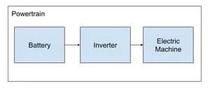
- Powertrain provides the power to the vehicle.
- Powertrain rerfers to the set of components that generate the power required to move the vehicle and deliver it to the wheels.
- The Block Diagram of Powertrain is shown below -
Duty Cycle -
- A duty cycle or power cycle is the fraction of one period in which a signal or system is active.
- Duty cycle is commonly expressed as a percentage or a ratio.
Calculation -
- As per previous study, total power required for moving the aircraft is 32.81 kW.
- For this purpose, lets take the example of REX-50 motor.
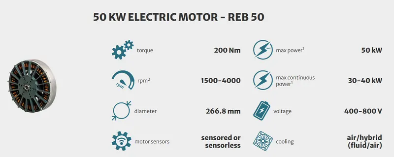
- Let the minimum voltage required is 400 V for 35 kW power and Battery voltage is 550V.
- Duty Cycle = 400/550 = 0.727
- Let losses be 10%.
- Minimum Voltage required will be 440 V after considering losses.
- Duty cycle will become 0.799
Input Parameters -
| Parameters |
Value |
| Mass of Aircraft | 664000 kg |
| Mass of tug | 20000 kg |
| Coefficient of Rolling Resistance | 0.0022 |
| Drag Coefficient | 0.02 |
| Air Density | 1.125 kg/`m^3` |
| Frontal Area | 350 `m^2` |
| Velocity | 2.22 m/s |
| Battery Voltage | 600V |
| Losses | 10% |
Simulink Model -
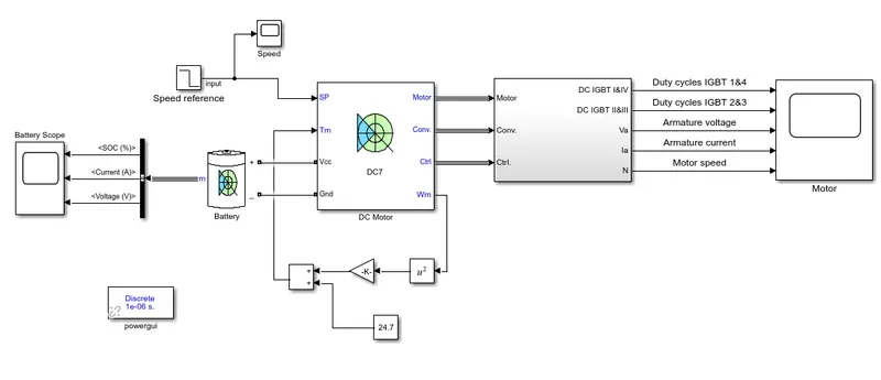
Results -
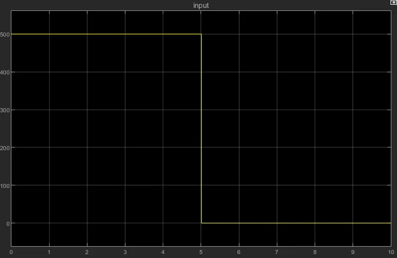
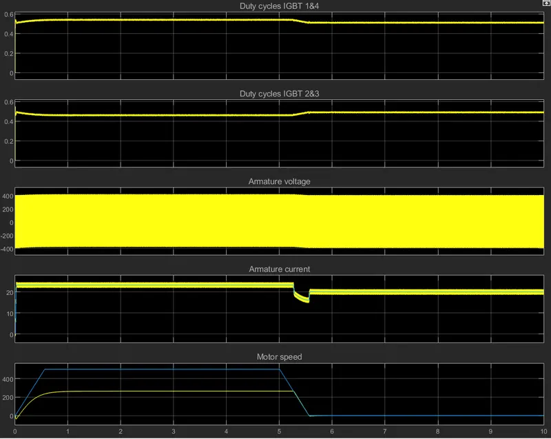
- Input Speed Signal -
- Battery results -
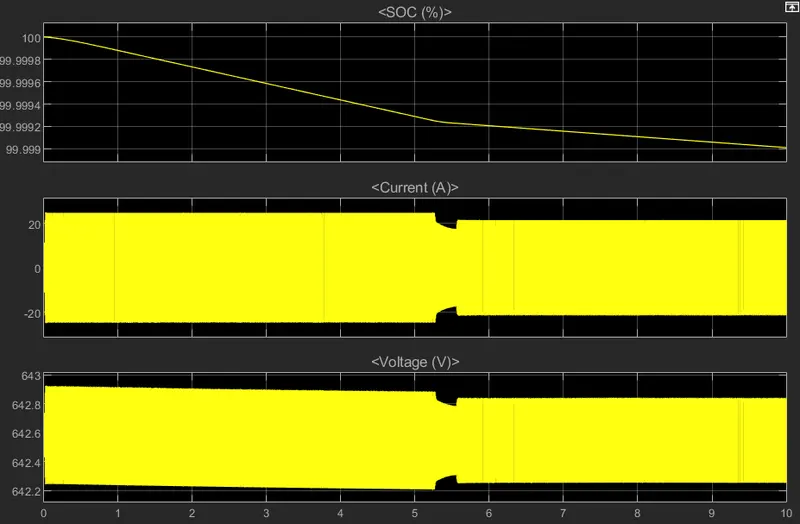
- Motor Results -
Excel sheet -
Google Drive Link for the models and excel sheet - Aircraft Towing Application