Project-1: Powertrain for aircraft in runways
EV LIVE SESSION 16
1)
| Aircraft | Max Gross Takeoff Weight |
|---|---|
| Antanov AN-225 | 1,411,000 lbs 640,000 kg |
| Airbus A380-800 | 1,268,000 lbs 575,000 kg |
| Boeing 747-800 | 987,000 lbs 447,700 kg |
| Airbus A340-500 | 820,000 lbs 372,000 kg |
| Boeing 777-300ER | 776,000 lbs 352,000 kg |
| Boeing 787-10 | 560,000 lbs 254,000 kg |
| Boeing 737-900 | 187,000 lbs 85,000 kg |
| Airbus A320-100 | 150,000 lbs 68,000 kg |
| Embraer 190 | 106,000 lbs 48,000 kg |
| Gulfstream G650 | 100,000 lbs 45,200 kg |
| Bombardier CRJ900 | 80,500 lbs 36,500 kg |
| Bombardier Q400 | 62,000 lbs 28,000 kg |
| Learjet 75 | 21,500 lbs 9,700 kg |
| Cessna Citation CJ4 | 17,200 lbs 7,800 kg |
| Beechcraft King Air B100 | 12,000 lbs 5,400 kg |
| Diamond DA50 RG | 4,400 lbs 2,000 kg |
| Beechcraft Bonanza G36 | 3,660 lbs 1,660 kg |
| Cessna 206H | 3,600 lbs 1,630 kg |
| Sirrus SR22 | 3,600 lbs 1,630 kg |
| Cessna 172R | 2,425 lbs 1,100 kg |
2)
The true AirSpeed may be larger or smaller than the ground speed depending on whether the wind component is aiding or abetting the direction of travel.
A plane making 550 mph through the air with a direct tail wind of 100 mph will be making 650 mph over the ground or ground speed. But the same plane heading into a head wind will only make 450 mph ground speed despite its 550 mph air speed. Ground speed determines how long it will take to reach the destination. But air speed determines fuel usage and stall speeds whether the plane flies or not.
3)
Airplanes get towed or pushed by tractors and tugs when jet blast from their engines or prop wash from their propellers will create a hazard to nearby buildings, ground crew, other aircraft & ground handling equipment. Moving aircraft from hangers to aprons does not require pilots if being towed.Airplanes get towed when the thrust of their engines creates a significant hazard to the immediate area surrounding them. Planes also get towed for maintenance purposes so pilots are not required to move the aircraft as airplane mechanics are trained in the use of the aircraft brakes while towing.This is why it is not recommended to use aircraft engine power to move it on the ground at Airport.
4)
The process of moving the airplane to runway when it is ready to take off is called Taxiing.Large jetliner passenger aircraft are pushed away from the passenger loading gate by a tug. This is a machine with wheels, some form of power such as an internal combustion engine, or a battery.
An airliner might be pushed backwards off the ramp, and onto a taxi way. Then the engines can start, the aircraft can proceed forward under its own power. A twin engine jet might not start the second engine until it is close to takeoff runway, clearance is certain.
A piston engine can run at idle power using only a small percentage of the fuel consumption used at operating power level. Turbine engines such as modern airliner turbo fan engine burn a lot of fuel once they are started. So, there is a lot of incentive to not run them until it is time to fly.
5)
Take Off Power
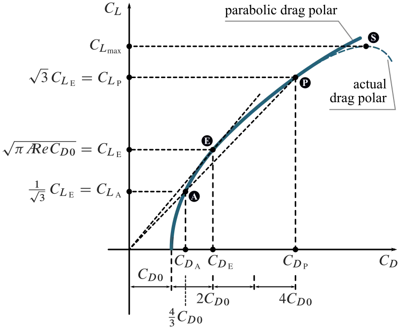
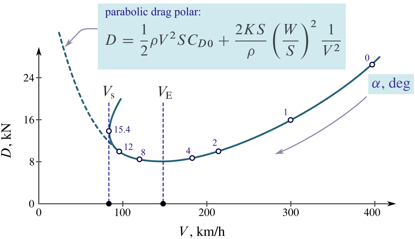
Thrust Technical Polar
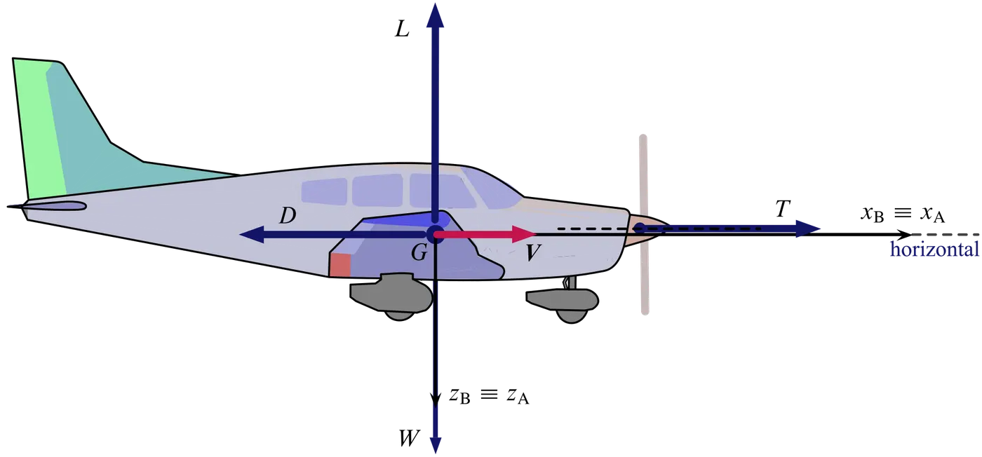
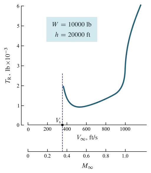
- TR">TRTR is the thrust required to fly at a given velocity in level, unaccelerated flight.
- Notice that minimum TR">TRTR is when airplane is flying at maximum E">EE, i.e. at maximum L/D">L/DL/D.
- E=L/D">E=L/DE=L/D, aircraft aerodynamic efficiency is an important aero-performance quantity.
- TR">TRTR for airplane at given altitude varies with velocity.
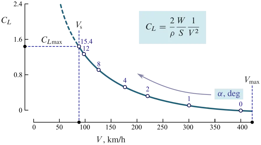
Example of required thrust calculation, for given aircraft weight W">WW and flight altitude h">hh:
- Select a flight speed V">VV.
- Calculate CL=W/(12ρV2S)">CL=W/(12ρV2S)CL=W/(12ρV2S).
- Calculate CD">CDCD from the polar: CD=CD0+CL2/(πARe)">CD=CD0+C2L/(πARe)CD=CD0+CL2/(πARe).
- Calculate the efficiency E=CL/CD">E=CL/CDE=CL/CD.
- Calculate TR=W/E">TR=W/ETR=W/E.
TR">TRTR is is how much thrust engine must produce to fly at selected speed – at the given altitude and at the given aircraft weight. It coincides with the amount of drag at the selected flight conditions.
The speed in level flight at the value CL">CLCL of the lift coefficient is expressed as follows:
That is, in level flight
Design and Construction of Aircraft tyre
Carcass plies are used to form the tire. They are sometimes called casing plies. An aircraft tyre is constructed for the purpose it serves.
- They support the weight of an aircraft while it is on the ground.
- It also provides the necessary traction for braking and stopping of an aeroplane.
- Tyre also helps to absorb the shock of landing and provide cushioning the roughness of takeoff, roll-out, and taxi operations.
Unlike an automobile or truck tyre, it does not have to carry a load for a long period of continuous operation. However, an aircraft tyre absorbs the high impact loads of landing, and also it’s operating at high speeds for a short time when required.
The aircraft tire is a combined structure of these basic materials:
- Rubber
- Nylon
- Cord
- Steel
These tires are combined together by a vulcanization process. Vulcanization process is a chemical process for converting polymers into more durable materials by introducing crosslinks. This process of treating crude or synthetic rubber or similar plastic material chemically to give it useful properties (such as elasticity, strength, and stability). There are mainly two types of tires:- Radial and Bias, each type has unique components reflecting different technologies applied to design, compounds and materials. To understand the difference between these two different types of tires, you have to first understand the meaning of ply rating. Ply rating is a rating of how many layers of rubber is on a tire. The number of layers of rubber and the angles at which they are laid dictate the strength and load capacity of the tire.
Bias-Ply Tire
The bias ply tire consists of layers of rubber running diagonally at approximately right angles to one another The bias tire are currently in maximum because of their strength. ITF (Inter Tread Reinforcing Fabric) is used in a bias tire. It provides additional high-speed stability, reduces tread distortion under load, protects the casing plies from damage and can act as wear indicators on re-manufactured tires.
Radial Ply Tire
In aircraft with radial ply tires, tires have layers of the tire running radially at an approximate perpendicular to the center line of the tire. Radial ply tires are low in weight as compared to the bias ply tire but have less strength.
Different Components Of Tire
Tread
It is a special composite rubber formulated to resist wear and tear, cutting, chunking, and heat build-up. Circumferential grooves are molded into the tread to disperse water from beneath the tread in wet runway conditions. The tread also helps to reduce the risk of aqua planning and improves traction and grip between the tread and runway surface.
Shoulder
Tire shoulder is the portion of the tread between the tread center and the tire sidewall. The tire shoulder offers support and protection to both the sidewall and the tread. The shoulder is a thick part of the tire, enabling the tire to more easily hold its form during cornering maneuvers.
Casing
The foundation strength of the tire is provided by the casing plies. Casing plies are layers of fabric coated with the high modulus of elasticity rubber on both sides to improve its elastic strength. Casing plies are wrapped around the beads (Bead is a wire used for attaching two things very strongly) for proper fitting.
Beads
The bead wire attaches the tire to the rim and ensures an airtight seal. Bead consist of bundles of high-tensile steel wires, each strand of which is coated in rubber compound and wound into coils of the correct diameter for given tire size.
Chafers
Chafers are made of tough nylon material and are fitted around the bead clinch area to resist chafing damage (It is damage caused to the skin of tire due to repetitive rubbing) to both tire and rim flange.
Sidewall
The sidewall is the area of the tire between the shoulder and the bead. The sidewalls of the tire are covered with a layer of specially formulated rubber treated with anti-oxidants. The sidewall of the tire protects the casing from the effects of weathering and offers resistance to cuts and flexing.
Inner tread
Tubeless tires have a layer of rubber bonded to the inside of the first casing ply from bead to bead to resist the permeation of nitrogen and moisture into the casing.
Under tread
The under tread is a layer of rubber that is designed to improve the adhesion between the tread and the casing plies.
Let’s go through some technical aspects of the tyre.
Retreading – Retreading is methods of restoring a worn tyre by renewing the tread area or by renewing the tread area plus one or both sidewalls. Repairs are included in the tyre retreading process.
Load Rating – Load rating is the maximum permissible load at a specified inflation pressure.
Ply Rating – Ply Rating is used to identify the maximum recommended load rating and inflation pressure for a specified tyre. It is an index of tyre strength.
Speed Rating – The speed rating is the maximum takeoff speed to which the tyre has been tested.
Skid Depth – Skid depth is the distance between the tread surface and the deepest groove as measured in the mould.
Aircraft tyres must have an approved speed and load rating and have sufficient clearance when retracted through landing gear to allow for tyre growth. Tyre growth is the increase in the size of the tyre due to centrifugal forces at high speed.
Aircraft tyres may be Tube-type or Tubeless
Tubeless tyres are more advantageous over tube-type. There is no longer the use of tube-type tyre in recent aviation. Nowadays all airliners are using tubeless tyres. Tubeless that are meant to be used without a tube has the word TUBELESS on the sidewall of the tyre.
Aircraft tyres may be Radial or Bias
Almost all airliners are using Radial tyre. Bias is an older design, and it’s mainly used for road vehicles. Radial tyres have the word RADIAL on the sidewall. Radial tires are more expensive than bias-ply tyres. Radial tires are in demand because of their lower life cycle cost and long term value.
Are aviation tyres are conductive?
Yes, Today’s tyres are conductive. Aircraft tyres are manufactured with tread rubber with conducting compounds to permit earthing of static charges.
In early days when tyres were not sufficiently conductive, aircraft used to have a conductive strip hanging down from the axle of the landing gear. Upon landing, this strip would be the first part of the aircraft to touch the earth. This discharges any static electricity accumulated on the outer surfaces of the aircraft. Now you don’t see them anymore.
What is the purpose of Chines in aviation tyre
Chines are also called deflectors. Chine tyre used on the nose wheel of aircraft, specially fuselage-mounted jet engines. It diverts runway water away from the engine inlets.
Chines are circumferential protrusions that are moulded into the sidewall of nose tyres that deflect water sideways to help reduce excess water ingestion into the engines. Tyres may have chines on one or both sides, depending on the number of nose tyres on the aircraft.
AIR PRESSURE IN TIRES
The real secret for the durability of airplane tires lies in something not known for its strength: -Air
“It’s really pressurized air that’s so strong,”
- by Lee Bartholomew(Lead test engineer for Michelin aircraft)
The pressure of the air inside the tires of the airplane is what supports the whole airplane. The tires are inflated to 200 psi (1379 kPa), which is about six times the pressure used in a car tire. This gives the tires extra strength to make all the high-speed landings. This amount of pressure varies in jets. For example, the tires on an F-16 fighter are inflated to 320 psi (2206 kpa). Tire inflation is the most critical issue when inspecting the installed tires. Overinflation and underinflation, both are not good for the tires. Overinflation causes damage to the tires by causing uneven tread wear, reduced traction, increased susceptibility to cutting and increased stress on the wheel assemblies. Underinflation is more damaging than overinflation. It produces uneven tread wear and shortens tire life due to excessive heating. Heat damages the tire rubber fabrics and compounds. Tire inflation is difficult to determine visually. Always use a gauge to check inflation. If servicing is required, dry nitrogen can be used due to its inability to sustain combustion. If regular shop air is used, inflation and damage are caused to the tire due to the difference in temperature and pressure. Nitrogen also helps to reduce corrosion at the wheel assembly.
Changes in Temperature
The important thing to remember related to tire inflation is the change in pressure with temperature changes. For every five to six degrees Fahrenheit change in temperature, there is approximately one-percent pressure change in the same direction. This should be taken into consideration if the airplane/aircraft is going to be subjected to extreme ground temperature changes. In that case, the tires should be sufficiently inflated to ensure that the minimum required pressure is maintained for the cooler climatic conditions. Always remember to check the tire pressures when they are at ambient temperature.
One thing that needs to be noted for newly installed tires is that the tire pressure will drop initially due to tire expansion, this thing is normal and to tackle this, the tire pressure should be checked closely until it stabilizes (usually about 12 hours) at rated inflation. If it still exhibits a significant pressure drop after that, the tire should be inspected for possible leaks and corrective action should be taken.
Protecting Tires
Tires should be taken care of by keeping them clean and free from oil, hydraulic fluids, grease, tar, and solvents as all these chemicals have a deteriorating effect on the rubber in the tires. Aircraft tires are affected by sunlight and weather extremes. Installation of protective covers can help protect tires on an airplane that are tied outside below.
Aircraft Tyre Standards
Each tyre manufacturer produces their own designs of the tyre with different tread patterns, wear patterns, wear limits etc, and in some cases, different names for the same part of the tyre. But all tyres must meet the approved standards before being accepted by the FAA or CAA.
All commercial aircraft tyres approved under FAA Requirement Technical Standard Order (TSO) C62. A TSO is a minimum performance standard for specified materials, parts, and appliances used on civil aircraft.
Each plane has a different number of tires depending on the type of airplane. The weight and speed of the aircraft determine the number of tires on the plane. Boeing 777s uses 14 tires, while the Airbus A380 uses 22. That means that if one suffers blow out or lose its tread during a high-speed landing there are plenty of others to support. Luckily, the tires don’t blow out as they are made very strong and durable by using high quality of different types of a layer of polymer.
The force that resists the motion of a body rolling on a surface is called the rolling resistance or the rolling friction.
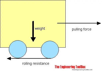
The rolling resistance can be expressed by the generic equation
Fr = c W (1)
where
Fr = rolling resistance or rolling friction (N, lbf)
c = rolling resistance coefficient - dimensionless (coefficient of rolling friction - CRF)
W = m ag
= normal force - or weight - of the body (N, lbf)
m = mass of body (kg, lb)
ag = acceleration of gravity (9.81 m/s2, 32.174 ft/s2)
Note that the rolling resistance coefficient - c - is influenced by different variables like wheel design, rolling surface, wheel dimensions and more.
The rolling resistance can alternatively be expressed as
Fr = cl W / r (2)
where
cl = rolling resistance coefficient - dimension length (coefficient of rolling friction) (mm, in)
r = radius of wheel (mm, in)
Some typical rolling coefficients:
| Rolling Resistance Coefficient | ||
|---|---|---|
| c | cl (mm) | |
| 0.001 - 0.002 | 0.5 | railroad steel wheels on steel rails |
| 0.001 | bicycle tire on wooden track | |
| 0.002 - 0.005 | low resistance tubeless tires | |
| 0.002 | bicycle tire on concrete | |
| 0.004 | bicycle tire on asphalt road | |
| 0.005 | dirty tram rails | |
| 0.006 - 0.01 | truck tire on asphalt | |
| 0.008 | bicycle tire on rough paved road | |
| 0.01 - 0.015 | ordinary car tires on concrete, new asphalt, cobbles small new | |
| 0.02 | car tires on tar or asphalt | |
| 0.02 | car tires on gravel - rolled new | |
| 0.03 | car tires on cobbles - large worn | |
| 0.04 - 0.08 | car tire on solid sand, gravel loose worn, soil medium hard | |
| 0.2 - 0.4 | car tire on loose sand | |
Stopping a 200-tonne aircraft landing at 180 mph requires a lot of braking force. To do this, the 787 has one brake unit on each of the eight wheels on the main gear assembly. On other aircraft types, the brake units are powered by the hydraulics system. An electrical signal is sent from the flight deck to hydraulic actuators near the main landing gear. Here, hydraulic fluid at 3,000 pound per square inch is used to force the brake unit against the wheel, thus slowing it down.
This system works fine, but the pipes and actuators that form this part of the hydraulic system come at a considerable weight cost. Extra weight means more fuel burn, which in turn increases costs and carbon emissions. What if the brakes could be powered a different way?
Designers did away with the use of the hydraulic system and all its associated architecture and instead used electricity to power the brakes. When the pilots press on the brake pedals, an electrical signal is sent to the brake unit on the wheel. Here, electrically powered actuators are used to press the carbon brake disc against the wheel, slowing it down.
By changing to electric brakes, a 787-8 saves 141 pounds per aircraft and a 787-9 saves 245 pounds. The brakes are also known as “plug and play” because electrical wiring replaces the traditional hydraulics and it’s much easier and quicker to change the brake units when needed. Smart features also allow engineers to monitor the brake performance more closely, giving a real-time measurement of wear on the carbon disks.
Electric brakes
The brake system on the 787 Dreamliner is controlled by the pilots pressing the tops of the rudder pedals under their feet, demanding the rate of braking which they require. This sends an electronic signal to the Left and Right Brake System Control Units (BSCUs).
These then send signals to the four Electronic Brake Actuator Controllers (EBAC) which control the rate of braking on the wheels. Each wheel has four Electric Brake Actuators (EBA), a kind of piston which presses against the carbon brake discs.

The brake disks themselves are made up of two parts. Firstly, there are the rotors. These are connected to the wheel by drive tabs (in the video below they are the black rectangles on the rotor disks). As these drive tabs are in contact with the inside of the wheel, they spin at the same speed. Depending on the brake manufacturer, there are either four or five of these rotors on each brake assembly.
The second part of the disks are the stators. These sit around each rotor and are fixed in place and thus don’t move. As the wheel turns, the rotors spin round inside the stators.
When the brakes are applied, the four EBAs apply pressure to the first stator. This in turn squeezes the stationary stators up against the spinning rotors and it’s this friction which slows the wheel down.
Anti-skid protection
When landing on slippery runways, there’s a chance that the wheels may start to skid as the brakes are applied. To stop this from happening and to maintain maximum effective braking, each wheel has anti-skid protection.
Using a variety of sources to determine the aircraft speed, the brake units know how fast the wheels should be spinning. If that speed drops significantly, it’s because the current brake pressure on that wheel is too great and the wheel is just skidding over the surface.
In this situation, the anti-skid system automatically reduces the braking on that wheel to a point where the skid stops before reapplying the pressure. All this is done in a fraction of a second.
Autobrake
Pressing on the brakes is pretty straight forward when taxiing in a straight line at low speed. However, when we’re landing in strong winds, it can be a little tricky. We need to use our feet on the rudder pedals to line the nose of the aircraft up with the runway centerline at the last moment. Then, whilst holding that position, slide our feet up to press the toe brakes. Really not very easy when moving at 160 mph.
To help us get the braking underway as soon as we touch down, we have the autobrake system.This provides automatic braking at a preselected rate as soon as the aircraft senses that it is on the ground. It also provides full braking pressure in the case of a rejected takeoff if the speed is above 85 knots (98 mph).
Brake temperature indication
With friction comes heat. As a result, each brake unit displays its temperature on the wheel synoptic page in the flight deck. Here, numerical values relating to brake temperature are shown next to each wheel. A value of 0-4.9 is in the normal range. When a temperature becomes 5.0 or above, an advisory message is displayed to the pilots.
Should the brakes become too hot, there’s a chance that the heat transferred to the wheels could cause the tires to explode. To stop this from happening, when a certain temperature is reached, fuse plugs in the tires melt. This allows the air to be released safely and slowly deflate the tires.
Parking brake
Every so often we need to engage the brakes and keep them on. This is particularly useful on long taxis to the runway and obviously when parked at the gate. The park brake is set by fully pressing down both toe brakes and pulling the parking brake lever up. With this set, we can then release the pressure from the pedals. To release, we just press the brake pedals again.
Reverse thrust
The final part of the braking process comes from reverse thrust. Just after we have touched down, we pull two levers on top of the thrust levers to engage the reverse thrust, a sort of “reverse gear” for jet engines.
This causes blockers inside the engine to deploy and a door in the side of the engine to slide backward. The air which normally leaves the engine out the back is deflected forward by the blockers and out through the door.
There are two stages of reverse thrust — idle reverse and max reverse. Idle reverse is used on most landings and max reverse is used when the landing performance requires it, normally when the aircraft is landing at hot or high elevation airfields.
This forward directed airflow helps slow the aircraft down but is most efficient at high speeds. If using max reverse, we drop this down to idle reverse at 60 knots (70 mph) and then back to normal thrust as we vacate the runway at around 20 knots (25 mph)
6)A
B)
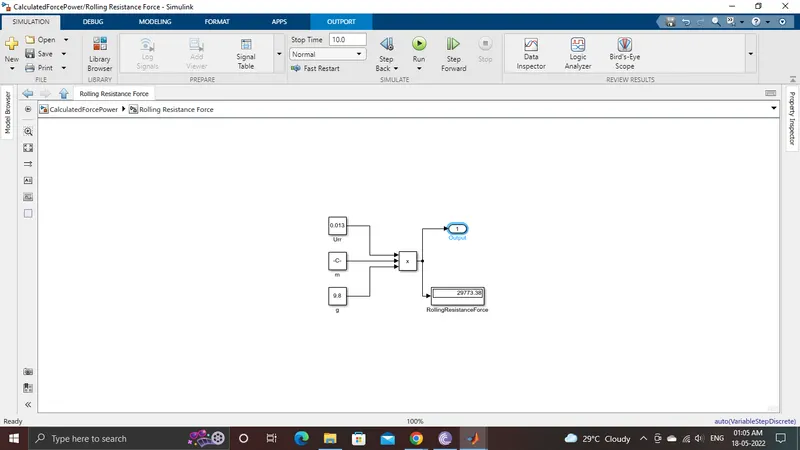
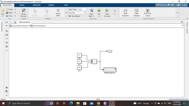
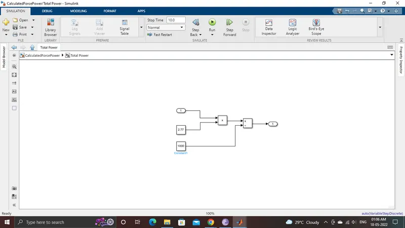
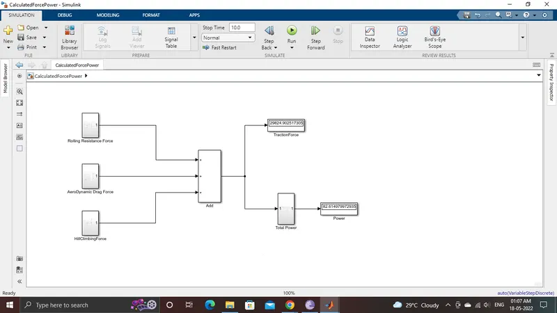
The simulink Model are as follows:

7)A)
Assuming the parameters and also the DC7 block,
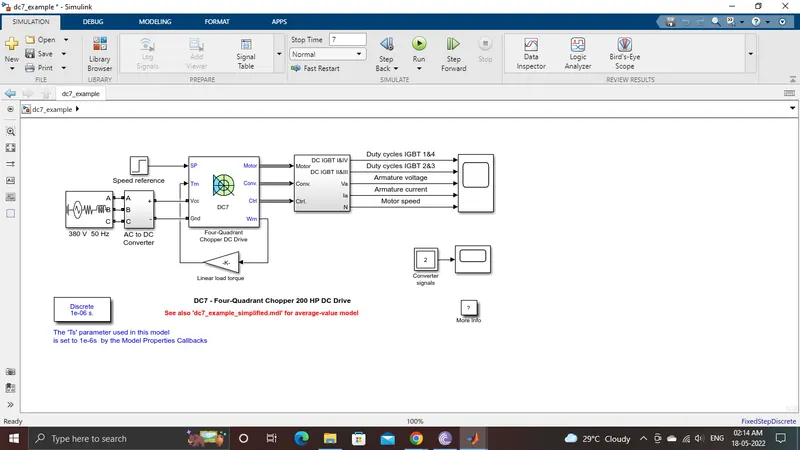
the duty cycle range to control the aircraft speed from zero to highest.
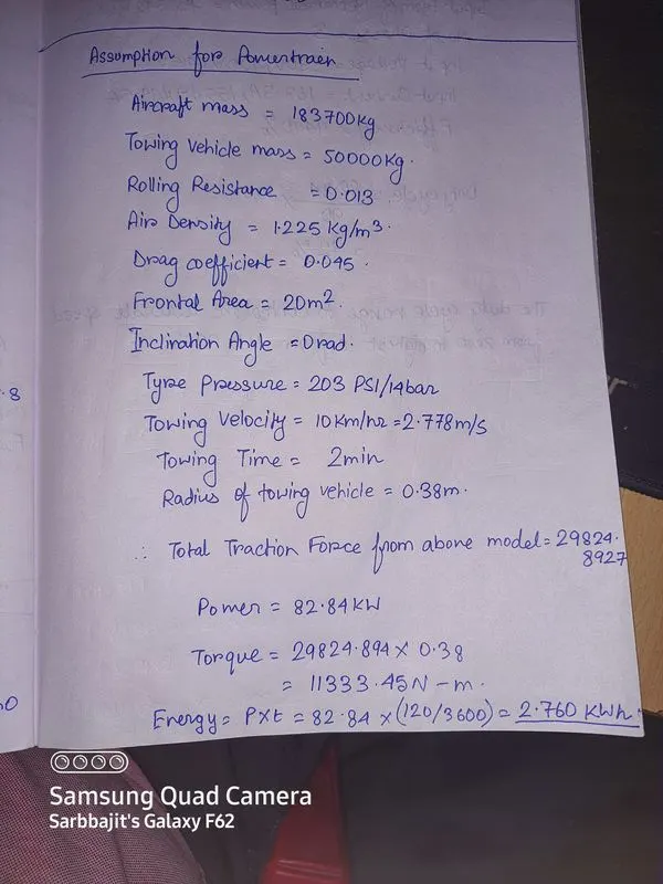
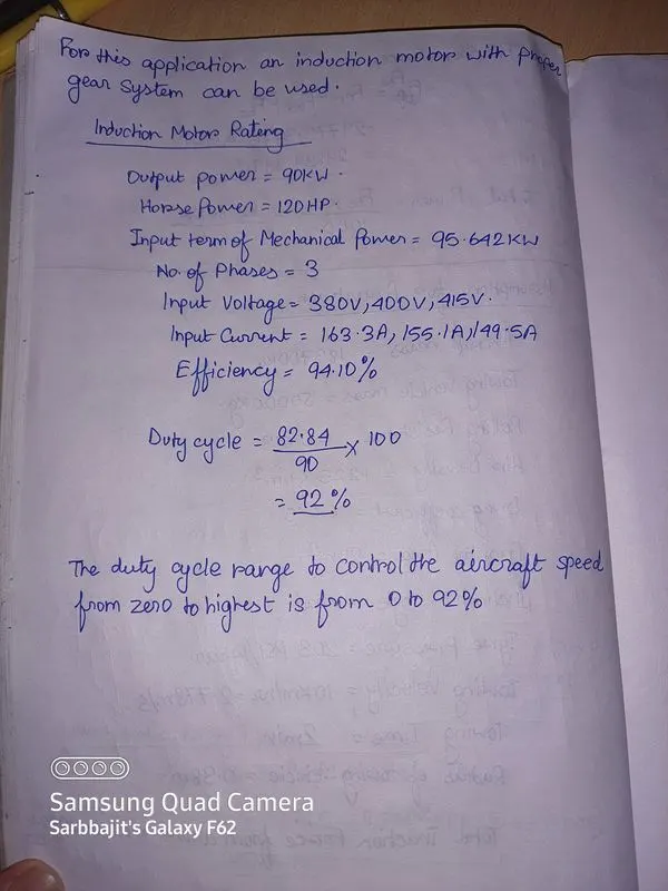
Block Diameter of PowerTrain
B)
parameters in excel sheet.