Project-1: Powertrain for aircraft in runways
Ans1)
List of various types of aircraft and total weight
MTOW-Maximum take-off weight, MLW-Maximum landing weight.
| Type | MTOW [kg] | MLW [tonnes] |
|---|---|---|
| Antonov An-225 | 640,000 | 591.7An |
| Scaled Composites Model 351 Stratolaunch | 589,670 | |
| Airbus A380-800 | 575,000 | 394 |
| Boeing 747-8F | 447,700 | 346.091 |
| Boeing 747-8 | 443,613 | 306.175 |
| Boeing 747-400ER | 412,770 | 295.742 |
| Antonov An-124-100M | 405,060 | 330 |
| Boeing 747-400 | 396,900 | 295.742 |
| Lockheed C-5 Galaxy | 381,000 | 288.417 |
| Boeing 747-200 | 377,840 | 285.700 |
| Boeing 747-300 | 377,840 | 260.320 |
| Airbus A340-500 | 371,950 | 240 |
| Airbus A340-600 | 367,400 | 256 |
| Boeing 777F | 347,800 | 260.816 |
| Boeing 777-300ER | 351,800 | 251.29 |
| Boeing 777-200LR | 347,450 | 223.168 |
| Boeing 747-100 | 340,200 | 265.300 |
| Airbus A350-1000 | 308,000 | 233.5 |
| Boeing 777-300 | 299,370 | 237.683 |
| Boeing 777-200ER | 297,550 | 213.00 |
| Airbus A340-300 | 276,700 | 190 |
| McDonnell Douglas MD-11 | 273,300 | 185 |
| Airbus A350-900 | 270,000 | 175 |
| Ilyushin Il-96M | 270,000 | 195.04 |
| McDonnell Douglas DC-10 | 256,280 | 183 |
| Boeing 787-9 | 254,000 | 192.777 |
| Boeing 787-10 | 254,000 | 201.849 |
| Airbus A340-200 | 253,500 | 181 |
| Airbus A330-900 | 251,000 | 191 |
| Ilyushin IL-96-300 | 250,000 | 175 |
| Airbus A330-300 | 242,000 | 185 |
| Airbus A330-200 | 242,000 | 180 |
| Lockheed L-1011-500 | 231,300 | 166.92 |
| Boeing 787-8 | 228,000 | 172.365 |
| Lockheed L-1011-200 | 211,400 | |
| Ilyushin IL-86 | 208,000 | 175 |
| Boeing 767-400ER | 204,000 | 158.758 |
| Airbus A300-600R | 192,000 | 140 |
| Boeing 767-300ER | 187,000 | 136.08 |
| Concorde | 185,000 | 111.1 |
| Airbus A300-600 | 163,000 | 138 |
| Boeing 767-300 | 159,000 | 136.078 |
| Airbus A310-300 | 157,000 | 124 |
| Vickers VC10 | 152,000 | 151.9 |
| Boeing 707-320B | 151,000 | 97.5 |
| Boeing 707-320C | 151,000 | 112.1 |
| Douglas DC-8-61 | 147,000 | |
| Airbus A310-200 | 142,000 | 123 |
| Airbus A400M | 141,000 | 122 |
| Douglas DC-8-32 | 140,000 | |
| Douglas DC-8-51 | 125,000 | |
| Boeing 757-300 | 124,000 | 101.6 |
| Boeing 707-120B | 117,000 | 86.3 |
| Boeing 757-200 | 116,000 | 89.9 |
| Boeing 720B | 106,000 | 79.5 |
| Boeing 720 | 104,000 | 79.5 |
| Tupolev Tu-154M | 104,000 | 80 |
| Tupolev Tu-204SM | 104,000 | 87.5 |
| Convair 880 | 87,500 | |
| Boeing 737-900 | 85,000 | 66.36 |
| Boeing 737-900ER | 85,000 | 71.35 |
| Boeing 727-200 Advanced | 84,000 | 70.1 |
| Airbus A321-100 | 83,000 | 77.8 |
| Boeing 737-800 | 79,000 | 65.32 |
| Boeing 727-200 | 78,000 | 68.1 |
| McDonnell-Douglas MD-83 | 73,000 | 63.28 |
Ans2-
Airspeed -
Airspeed is the speed at which aircraft is moving with respect to the air.
ground speed-
It is the speed of the aircraft with respect to the ground.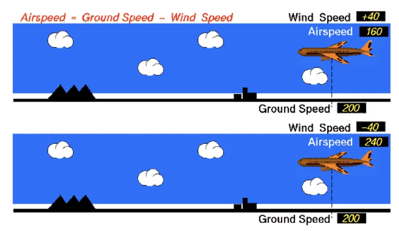
Ans3)- The reason why it is not recommended to use aircraft engine power to move it on the ground at Airport-
1 Aircraft engine uses so much energy so it's better to use towing the aircraft in place of the aircraft engine
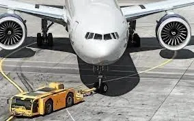
2 Pilot will not have a wide range of view so the pilot needs an instructor to use the engine.
3 Noise by the aircraft engine is so much so it's not good to use the engine
4 Pilot cannot judge that any aircraft wings are near to the wings of his aircraft so accident chances increase so it's not good to use aircraft engine
So generally we use towing to move the aircraft when it is not on the runway.
Ans 4)
The way aircraft pushed on the runway before take-off-
Gnarly aircraft use tug to move the aircraft into the runway. Because it is safer to use another vehicle to move the aircraft because it can damage the building and by itself, if not properly managed. So towing only is the better option to move the aircraft to the runway. After that throttle can be used to move the aircraft which is called taxiing.
Ans5)
Take-off power-
The amount of power required for any aircraft to take off is called Take-off power. The power required for aircraft at land and take-off is very high compared to all operations. generally, take off the power will be 8000 watt-hour
Tyre design -
In any aircraft number of tyres increases as the load and speed increase. Aircraft tires are used only when aircraft take off and when aircraft land but at this time pressure on the tire is very high so the tire is designed to withstand higher power below are the aircraft tire layers are shown by which tyres are made.
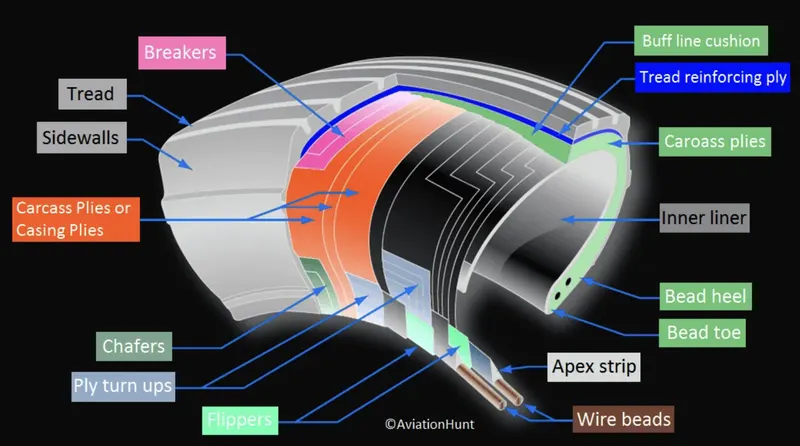
Aircraft tires structure made by a combination of this material-
1 Rubber
2 Nylon
3 Cord
4 Steal
These tires are combined by a vulcanized process. This process is a chemical process to convert polymers into more durable materials by introducing cross-links. This process is useful to increase the strength, elasticity, and stability of the tire. There are two types of tires Radial and bias. Each tire has a unique property. To understand the difference between these two tires we need to know about the ply rating. Ply Rating is the number of rubbers layers added to the tyre. The number of layers of rubber and the angles at which they are laid dictate the strength and load capacity of the tire.
Bais-ply tire-
In bais ply, rubber layers are running diagonally that are perpendicular to each other. These tyres are used maximum due to maximum strength. Inter treads Reinforced fabric used in a bias tyre. It provides extra high-speed stability. protects the casing plies from damage and can act as wear indicators on re-manufactured tires.
Radial ply tyre-
It is having several tires running radially approximate perpendicular to the centerline of the tire It is low in weight but has less strength compared to the bias tire.
Different components of the tyre-
Different Components Of Tire-
Shoulder
It is the portion of the tread used in between the tread center and the tire sidewall. The tire shoulder offers support and protection to both the sidewall and the tread. The shoulder is a thick part of the tire, enabling the tire to more easily hold its form during cornering maneuvers.
Beads
The bead wire attaches the tire to the rim and ensures an airtight seal. Beads consist of bundles of high-tensile steel wires, each strand of which is coated in a rubber compound and wound into coils of the correct diameter for a given tire size.
Tread
It is special composite rubber used to reduce wear and tear, cutting, chunking, and heat build-up. Circumferential grooves are used in the tread to not get affected by the water beneath the tread in wet runway conditions. The tread also helps to reduce the risk of aqua planning and improves traction and grip between the tread and runway surface.
Under tread
The under tread is a layer of rubber that is designed to improve the adhesion between the tread and the casing plies.
Sidewall
The sidewall is the area of the tire between the shoulder and the bead. The sidewalls of the tire are covered with a layer of specially formulated rubber treated with anti-oxidants. The sidewall of the tire protects the casing from the effects of weathering and offers resistance to cuts and flexing.
Casing
The foundation strength of the tire is provided by the casing plies. Casing plies are layers of fabric coated with a high modulus of elasticity rubber on both sides to improve its elastic strength.
Chafers
Chafers are made of tough nylon material and are fitted around the bead clinch area to resist chafing damage (It is damage caused to the skin of the tire due to repetitive rubbing) to both tire and rim flange.
Inner tread
Tubeless tires have a layer of rubber bonded to the inside of the first casing ply from bead to bead to resist the permeation of nitrogen and moisture into the casing.
Rolling resistance-
It is the force resisting the speed of the vehicle. And also it is the energy required by the tire to keep moving at constant speed on the runway. It is also called rolling friction and rolling drag. This is having two forms1 hysteresis loss 2 It is due to the permanent deformation of an object or surface.
Fr=Crr * N
Crr=friction coefficient
N= normal force
Fr = Friction force
Tyre pressure-
Aircraft tires are usually made for high pressure for a short duration of time due to the reason that when aircraft are landing or take-off that time tires will have high pressure. An aircraft can handle a 38-tonne load. Aircraft Tyre is used to have high pressure of about 200 pounds per square inch. Boeing 777-300 ER main tires are inflated to 220 psi.
Brake forces when landing an aircraft-
Aircraft Disc brake-
An electric signal is sent by the pilot from the deck to the hydraulic actuator near the main landing gear. Now here high pressure is applied by the disc to the wheels against the motion thus wheels start slowing down.
Reverse the thrust brake-
when the Pilot is reversing the thrust of the aircraft then this thrust will oppose the motion of the aircraft
so it will slow down.
Airbag brake-
when the Plane is landing then air bad is open which opposes the speed of the craft due to airflow opposed by air bad. so aircraft will start slowing down.
Ans 6-
calculation of force and power required to push/pull an aircraft by a towing vehicle-
Assumptions for Boeing 747-200-
aircraft mass(M)=396,900 kg
mass of the towing vehicle(m1)=60000 kg
coefficient of rolling resistance=0.02
frontal area(A)=40 m^2
Aircraft drag coefficient(Cd1)=0.7
Towing vehicle drag coefficient(Cd2)=0.12
density of air(rho)=1.225kg/m^3
gravity(g)=9.81m/sec^2
speed of the aircraft(v)=6 m/sec
solution-
Rolling resistance force for the aircraft(Frra)=coefficient of rolling resistance*M*g
=0.02*396900*9.81
Rolling resistance force for the aircraft(Frra)=77871.78 N
for towing vehicle(Frrv)=coefficient of rolling resistance*M1*g
=0.02*60000*9.81
for towing vehicle(Frrv)=11772N
when the vehicle is towing the aircraft then we need total rolling resistance then we need to add this
Total rolling resistance force=Frra+Frrv
=11772+77871.78
Total rolling resistance =89643.78N
Aerodynamic drag force=1/2*ρ*A*V^2*(Cd(aircraft)+Cd(vehicle)
=1/2*1.225*40*6^2(0.12+0.7)
Aerodynamic drag force =723.24N
Total force for the towing vehicle=Aerodynamic drag force+Total rolling resistance force
=723.24+89643.78
Total force for the towing vehicle =90367.02 N
Total power for the towing vehicle= total force*velocity
=90367.02*6
=542202.12watts
Total power for the towing vehicle =542202.12 Kwatts
The force and power required by the towing vehicle are 92536.74 N, and 542202.12 k.watts.
Ans6 B-
Matlab model for the above problem
required software-Matlab Simulink
Blocks required-
constant block, product block, add block, square block
procedure-
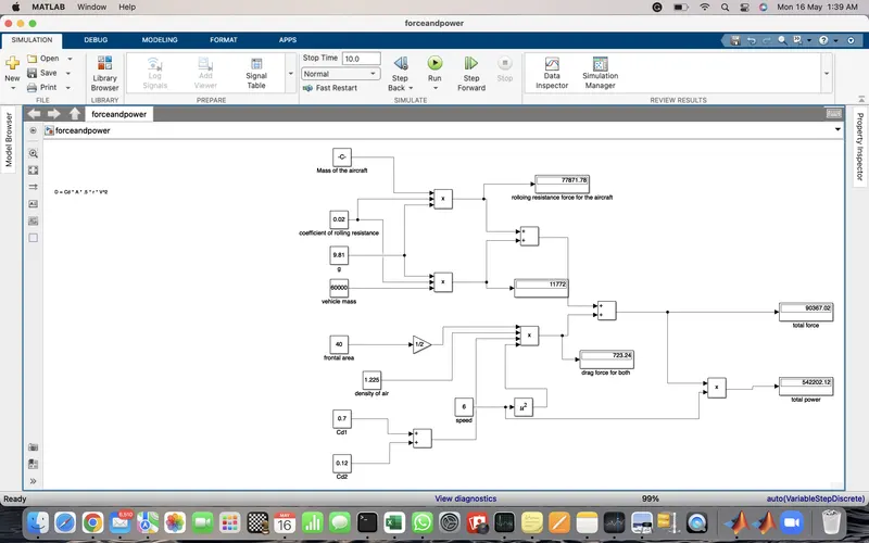
I have calculated individual rolling resistance force and Aerodynamics force and added them up as shown below.
By multiplying total force by velocity we have gotten total power as in the previous problem
I have given run time as 10 sec
We have run the model
Output-
As shown above, I have gotten the total force and power as 90367.02 N and 542202.12 k.watts.
Ans7A-
Make a towing vehicle with an electric motor so we need to calculate the torque required for the motor to be used as towing
Assumptions for Airbus A380-800
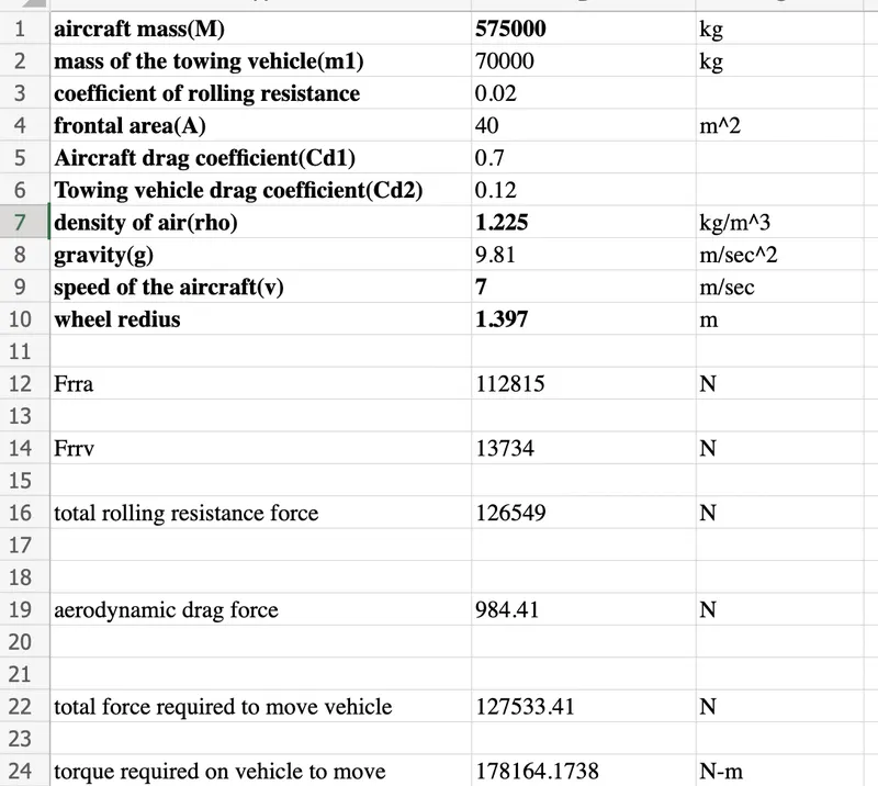
aircraft mass(M)=575000 kg
mass of the towing vehicle(m1)=70000 kg
coefficient of rolling resistance=0.02
frontal area(A)=40 m^2
Aircraft drag coefficient(Cd1)=0.7
Towing vehicle drag coefficient(Cd2)=0.12
density of air(rho)=1.225kg/m^3
gravity(g)=9.81m/sec^2
speed of the aircraft(v)=7 m/sec
wheel redius=55inch=1.397m
solution-
Rolling resistance force for the aircraft(Frra)=coefficient of rolling resistance*M*g
=0.02*575000*9.81
Rolling resistance force for the aircraft(Frra)=112815 N
for towing vehicle(Frrv)=coefficient of rolling resistance*M1*g
=0.02*70000*9.81
for towing vehicle(Frrv)=13734N
when the vehicle is towing the aircraft then we need total rolling resistance then we need to add this
Total rolling resistance force=Frra+Frrv
=112815+13734
Total rolling resistance force =126549N
Aerodynamic drag force=1/2*ρ*A*V^2*(Cd(aircraft)+Cd(vehicle)
=1/2*1.225*40*7^2(0.12+0.7)
Aerodynamic drag force =984.41N
Total force for the towing vehicle=Aerodynamic drag force+Total rolling resistance force
=984.41+126549
Total force for the towing vehicle =127533.41N
so Torque=127533.41*1.397
=178164.17377 N-m
I have used DC7 four-quadrant chopper drive to perform this task as shown below-
I have given input voltage as 10000 volt
and load torque=178164.17377 N-m
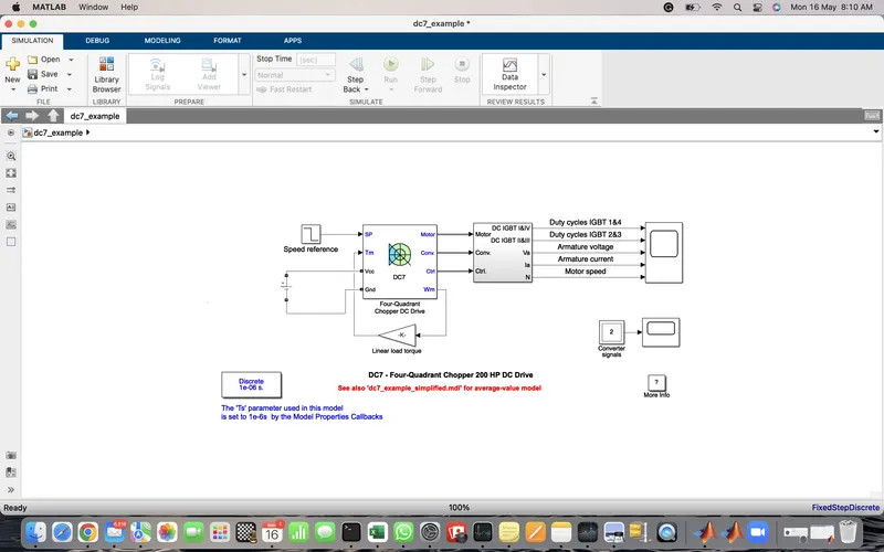
And I have given the run time as 7 seconds and I have run the model.
Output-
Below is graph shows the duty cycle, input voltage, current and speed of the motor.
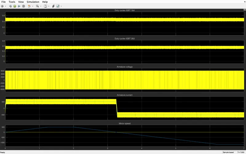
after zooming we have clear picture of duty cycle, armature current, armature voltage, motor speed
as shown below
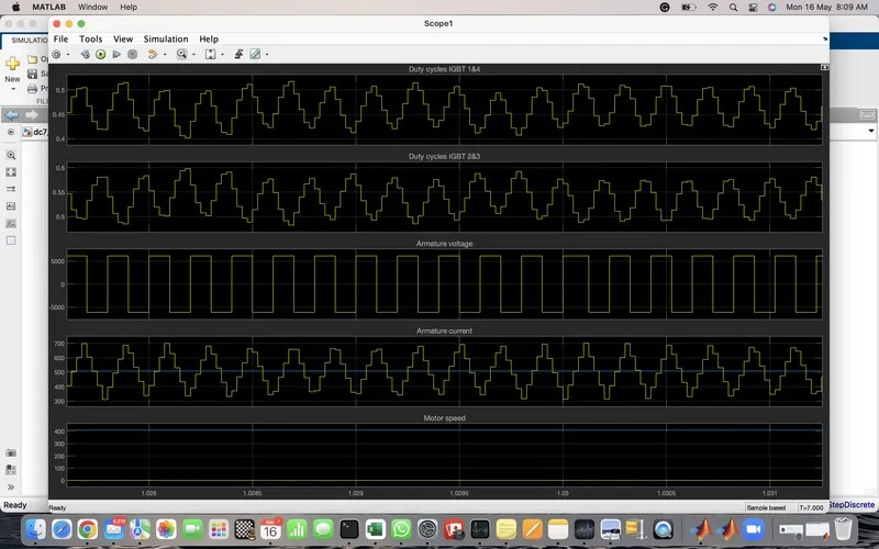
Below is the excel sheet used to calculate the torque required for the vehicle to move by assumption of above problem