Project-1: Powertrain for aircraft in runways
1.
When looking at different aircraft's specifications or in POHs/AFMs, there are several different weights of the aircraft mentioned (e.g. maximum take-off weight, maximum landing weight, operating empty weight)
The different terms represent different weights or masses1. For each flight, the weights are taken into account for several reasons.
A brief description about these is below:
Manufacturer's Empty Weight (MEW) :
Also called Manufacturer's Weight Empty (MWE) or Licensed Empty Weight
It is the weight of the aircraft "as built" and includes the weight of the structure, power plant, furnishings, installations, systems and other equipment that are considered an integral part of an aircraft.
This excludes any baggage, passengers, or usable fuel2.
Zero-Fuel Weight (ZFW) :
This is the total weight of the airplane and all its contents (including unusable fuel), but excluding the total weight of the usable fuel on board.
As a flight progresses and fuel is consumed, the total weight of the airplane reduces, but the ZFW remains constant.
Maximum zero fuel weight (MZFW) is the maximum weight allowed before usable fuel and other specified usable agents (engine injection fluid, and other consumable propulsion agents) are loaded.
Operating Empty Weight (OEW) : (Roughly equivalent to basic empty weight on light aircraft)
It is the basic weight of an aircraft including the crew, all fluids necessary for operation such as engine oil, engine coolant, water, unusable fuel and all operator items and equipment required for flight but excluding usable fuel and the payload.
Payload :
It is the carrying capacity of an aircraft. It includes cargo, people, extra fuel. In the case of a commercial airliner, it may refer only to revenue-generating cargo or paying passengers.
Maximum Take-off Weight (MTOW) :
This is the maximum weight at which the pilot of the aircraft is allowed to attempt to take off3
Regulated Take-off Weight (RTOW) :
Depending on different factors (e.g. flap setting, altitude, air temperature, length of runway), RTOW or maximum permissible takeoff weight varies for each takeoff. It can never be higher than MTOW.
Maximum Landing Weight (MLW) :
This maximum weight at which an aircraft is permitted to land3.
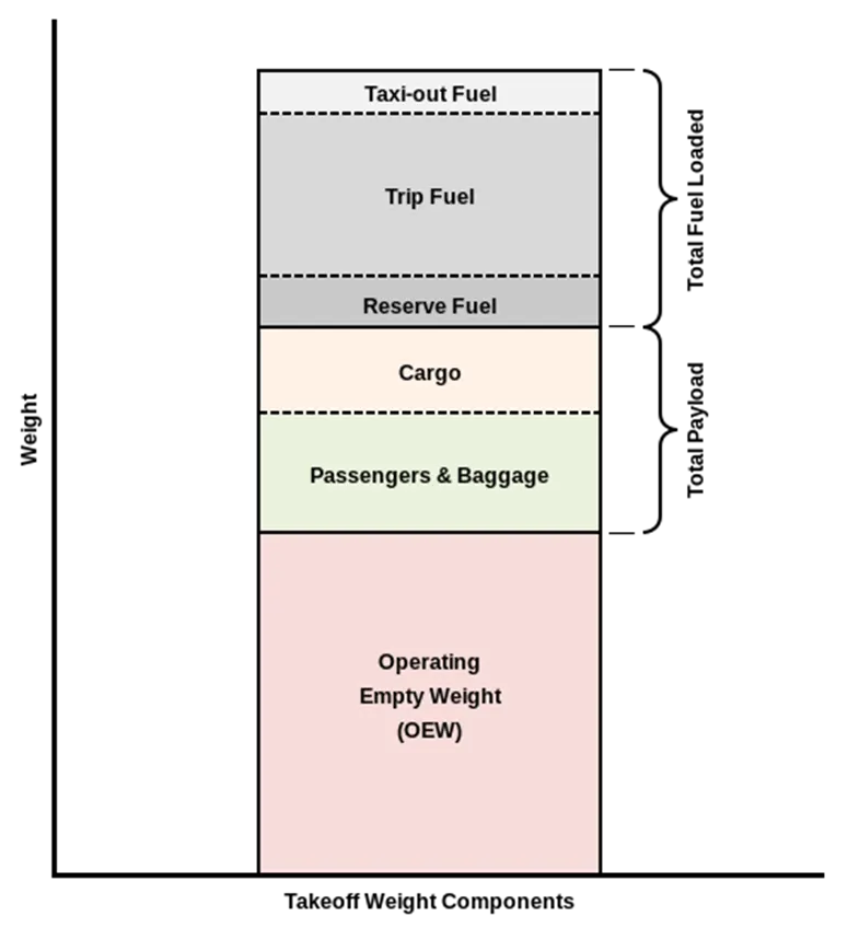
The following image depicts takeoff weight components.
Typical Airplane Weights
Below is a table of some of the most common aircraft flying around our skies today:
|
Aircraft |
Empty Weight |
Max Fuel Weight |
Max Cargo Weight |
Max Gross Takeoff Weight |
|
Antanov AN-225 |
628,000 lbs |
661,400 lbs |
417,000 lbs |
1,411,000 lbs |
|
Airbus A380-800 |
611,000 lbs |
560,000 lbs |
185,000 lbs |
1,268,000 lbs |
|
Boeing 747-800 |
485,300 lbs |
427,400 lbs |
295,000 lbs |
987,000 lbs |
|
Airbus A340-500 |
370,000 lbs |
386,300 lbs |
119,000 lbs |
820,000 lbs |
|
Boeing 777-300ER |
370,000 lbs 168,000 kg |
320,800 lbs 145,500 kg |
148,000 lbs |
776,000 lbs |
|
Boeing 787-10 |
299,000 lbs 135,500 kg |
223,500 lbs |
126,300 lbs 57,300 kg |
560,000 lbs |
|
Boeing 737-900 |
98,500 lbs |
53,100 lbs |
44,600 lbs |
187,000 lbs |
|
Airbus A320-100 |
93,900 lbs |
48,700 lbs |
44,000 lbs |
150,000 lbs |
|
Embraer 190 |
63,500 lbs |
28,600 lbs |
28,800 lbs |
106,000 lbs |
|
Gulfstream G650 |
54,000 lbs 24,500 kg |
48,200 lbs 21,900 kg |
6,500 lbs |
100,000 lbs |
|
Bombardier CRJ900 |
48,160 lbs 21,850 kg |
19,600 lbs 8,900 kg |
6,075 lbs 2,760 kg |
80,500 lbs |
|
Bombardier Q400 |
39,300 lbs |
11,700 lbs |
18,700 lbs |
62,000 lbs |
|
Learjet 75 |
13,900 lbs 6,300 kg |
6,060 lbs |
2,900 lbs |
21,500 lbs |
|
Cessna Citation CJ4 |
10,300 lbs 4,700 kg |
5,800 lbs |
2,200 lbs 1,000 kg |
17,200 lbs |
|
Beechcraft King Air B100 |
7,100 lbs 3,200 kg |
3,200 lbs |
4,150 lbs |
12,000 lbs |
|
Diamond DA50 RG |
3,200 lbs |
340 lbs |
1,250 lbs |
4,400 lbs |
|
Beechcraft Bonanza G36 |
2,500 lbs 1,150 kg |
450 lbs |
850 lbs |
3,660 lbs |
|
Cessna 206H |
2,200 lbs |
520 lbs |
1,150 lbs |
3,600 lbs |
|
Sirrus SR22 |
2,250 lbs 1,000 kg |
485 lbs |
950 lbs |
3,600 lbs |
|
Cessna 172R |
1,700 lbs |
380 lbs |
560 lbs |
2,425 lbs |
2.
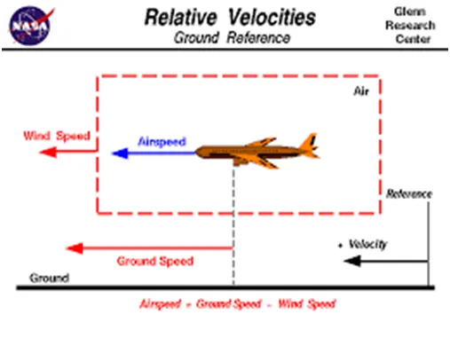
The ground speed is the speed the aircraft is making over ground below. The indicated airspeed (IAS) is the speed shown on the airspeed indicator. This will be different than the ground speed for various reasons, such as wind and the attitude of the aircraft.
For example, if the aircraft is diving then the IAS will be greater than the ground speed. In fact, if the aircraft were diving straight down, then the ground speed could be 0 while the IAS was hundreds of knots per hour.
The indicated airspeed is the usual measure used in flight.
The ground speed can be calculated to estimate the time of arrival of the aircraft at some destination.
Airspeed, in contrast, is how fast an airplane is really flying strictly under its own power, which is calculated by subtracting the wind speed from the ground speed
3.
When an airplane uses reverse thrust it takes a high power setting to get the aircraft moving initially. This creates a high-speed wind that can easily damage the airport terminal, jetway, surrounding ground vehicles, baggage, and ground personnel and cause debris to be ingested by the engine – not good
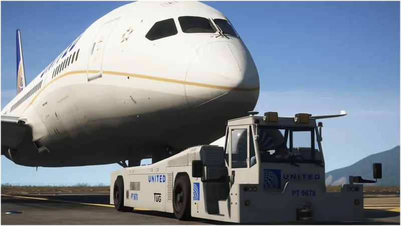
All large aircraft are pushed back , they could use there power to do it but due to the noise and fumes plus they burn a lot of fuel. Sometimes they are towed into a spot due to it being a small parking space for safty
- Far greater safety because the tow truck operator has a much better view of the entire area surrounding and under the aircraft
- The vehicle driver is in communication with the pilots to ensure aircraft braking can be applied if needed in an emergency
- With the aid of ground personnel who walk under the wingtips, the tow truck driver can precisely position the aircraft and ensure it does not contact any structure,vehicle, person or aircraft
- It allows the airports ground controllers to get aircraft moved with much greater time constraints thus improving the flow around the apron and gate areas
Engine power is used all the time to move aircraft on the ground. I think you mean in the ramp area. if, so, again, engine power is used all the time in the ramp. They do get pushed back because only aircraft with engines on the tail can power-back due to FOD. Sometimes, if it’s a tight area, a tug will be used.
4.
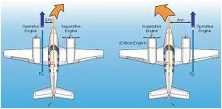
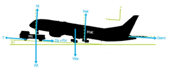
A so-called pushback truck reverses the aircraft into taxiing position, pushing it with a towbar attached to the nose-wheel strut. Or, in the most modern versions, by actually lifting the wheel. That speeds up coupling and decoupling. The aircraft taxis to the runway to depart at the agreed time Steering is achieved by turning a nose wheel or tail wheel/rudder; the pilot controls the direction travelled with their feet. Larger jet aircraft have a tiller wheel on the left side of the cockpit that acts as a steering wheel allowing the nosewheel to be turned hydraulically. Most planes use a long runway before takeoff to gain enough speed for the plane to lift up into the air. Most airplanes can take off only if they are moving fast enough. The force of lift needs to be stronger than the force of weight.
The airplane may be pushed or pulled by landing gear or wing struts since they're known to be strong enough to drag the airplane through the air. To allow for turns, a person may either pick up or push down on the tail to raise either the nose wheel or tail wheel off the ground, then rotate the airplane by hand, Pilots adjust the track on the runway by using the rudder and nose-wheel steering. Some airplanes have an interconnection between the rudder pedals and the nose-wheel steering, allowing pilots to make all of the runway steering corrections via the rudder pedals.
5.
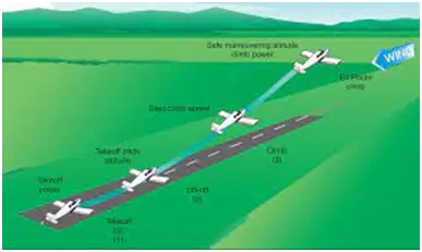
The amount of power that an engine is allowed to produce for a limited period of time for takeoff. The use of takeoff power is usually limited to 5 min for reciprocating engines and up to 2½ min for gas turbine engines. This may not always be the case. Specifically, with respect to reciprocating engines, it is the brake horsepower developed under standard, sea-level conditions and under the maximum conditions of the crankshaft rotational speed and the engine manifold pressure approved for the normal take-off. It is limited in continuous use to the period of time shown in the approved engine specifications. With respect to gas turbine engines, it is the thrust developed under static conditions at a specified altitude and atmospheric conditions of the rotor shaft rotational speed and gas temperature approved for the normal takeoff. It is limited in continuous use to the period of time shown in the approved engine specifications.
Whatever power setting results from the instructions in the aircraft manual that tell you how to set power for takeoff under the prevailing conditions. That can be anything from “use full throttle for takeoff” to a textbook on calculating what to set, sometimes augmented with software for the purpose.
On really big airplanes, you don’t just use full throttle because that is incredibly expensive, both in fuel you didn’t have to burn and in engine maintenance. Not to mention being uncomfortable and making a lot of unnecessary noise. So there is a formula that gives the correct power setting for an acceptable safety margin, given the weight of the airplane, the weather, the runway length and conditions, and possibly other factors.
TIRES :
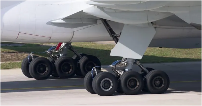
One thing you see almost never see when an airplane lands is a blowout. Think about that: Again and again, the tires hit tarmac at 170 miles per hour and bear the weight of a modest office building. And they nail it. Every time. Aircraft tires are amazing when you think about it. The typical airliner tire can handle a 38-ton load. It can meet the ground 500 times before needing a re-tread, a refresh it can take on seven times in its life.
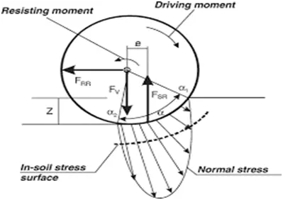
The tires themselves aren't terribly large--- a Boeing 737 rides on 27x7.75 R15 rubber. In English, that means it is 27 inches in diameter, 7.75 inches wide, and wrapped around a 15-inch wheel. The sidewalls aren't terribly thick, and the strength of the tire lies in the cords embedded below the tread, Bartholomew says. They're typically nylon, and more recently a variety known as aramid. Each layer of the casing contributes to its load bearing and air pressure resisting capabilities. Of course, tires can fail, especially when under-inflated or overloaded. Treads can come off and casings can blow out.
Airplane tires are very different from car, truck or bicycle tires. In fact, airplane tires have about as much in common with these tires as they do with running shoes! They are all made of rubber. They all contain air. They all provide support and cushioning for what’s on top of them. But that's where the similarities end.
Airplane tires have to deal with enormous forces when the plane lands. They especially have to deal with friction. Friction occurs when two surfaces move against each other, like when you rub your hands together.
Airplane tires create friction when they hit the runway. This friction generates heat. It also and wears down the outside layer of the tire. Because of this, airplane tires are reinforced with strong, flexible materials. One of these materials is a super-strong plastic called Kevlar. Kevlar is strong, flexible, heat-resistant and lightweight.
It’s important for airplane tires to be flexible. Flexibility lets airplane tires absorb more of the shock of landing. Flexibility also slows the wearing down of tires. 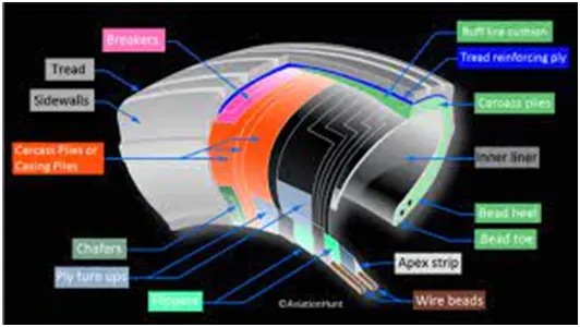
Part B:
6 (a)
Here to calculate required to push / pull an aircraft by a towing vehicle. the following aircraft model is considered below and its calculations are done
Taking the value of aircraft 310, the specifications are :
Mass : 164000kg
Height : 15.80m
Width : 43.90m
Frontal area(A) : height * width = 15.80 * 43.90
= 693.62m2
Drag coefficient (cd) : 0.0265
Air density (ρ) : 1.225kg/m3
Considering the values of towing vehicle TBL280,
Mass : 35000kg
Height : 2.0m
Width : 3.4m
Frontal area (A) : height * width = 2.0 * 3.4
= 6.8m2
Tyre size (R) : 22’’ = 0.5588m
Drag coefficient (Cd) : 0.6
Air density (ρ) : 1.225kg/ m3
Speed (V) : 32kmph = 32 * 5/18
= 8.89m/s
Now lets calculate the forces acting on the aircraft by towing vehicle
Rolling resistance force ; Air drag force
Rolling resistance force (Frr)1 : µrr * m * g
= 0.02 * 164000 * 9.8
= 32144 N
Rolling resistance force (Frr)1 = 32144 N (acting on aircraft)
Rolling resistance force (Frr)2 : µrr * m * g
= 0.02 * 35000 * 9.8
= 6860 N
Rolling resistance force (Frr)2 = 6860 N (acting on towing vehicle)
Total rolling resistance force (Frr) : (Frr)1 + (Frr)2
= 6860 + 32144
= 39004 N
Total rolling resistance force (Frr) = 39004 N
Air drag force (Fad)1 : 1/2 * ρ * A *Cd * V2
= 1/2 * 1.225 * 693.62 * 0.0265 * 8.892
= 889.77 N
Air drag force (Fad)1 = 889.77 N (acting on aircraft)
Air drag force (Fad)2 : 1/2 * ρ * A *Cd * V2
= 1/2 * 1.225 * 6.8 * 0.6 * 8.892
= 197.5 N
Air drag force (Fad)2 = 197.5 N (acting on towing vehicle)
Total Air drag force (Fad) : (Fad)1 + (Fad)2
= 889.77 + 197.5
=1087.3 N
Total Air drag force (Fad) = 1087.3N
Total force acting (Ft) : Frr + Fad
= 39004 + 1087.3
= 40091.3 N
Total power Pt : Ft * V
= 40091.3 * 8.89
= 356411.66 W
= 356.41 Kw
Total power (Pt) = 356.41 Kw
Total force required to push / pull an aircraft by a towing vehicle = 40091.3 N
Total power required to push / pull an aircraft by a towing vehicle = 356.41 Kw
6(b).
Develop the model for the calculated force and power using Simulink.
so here according to the above performed calculations the model is to be build in the SIMULINK
all the calculated forces are implemented in the form of blocks and particular values are assigned
below image represents the SIMULINK model which is built according to the performed calculation
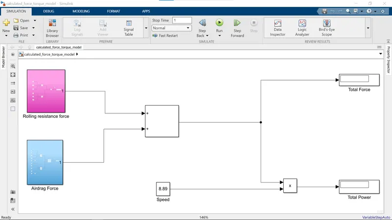
* here if we observe the two subsystems are created one is for rolling resistance force and another one is for airdrag force and those two blocks are added withe the help of sum block and are connected to the display port
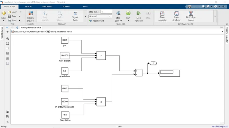 * here the constant blocks are taken and the calculated values are defined in those constant blocks and the mathematical operations are performed the calculations for aircraft and towing vehicle, and connected to the display and the value obtained in the display will be very close or will be exact value with the calculated values
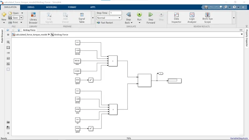
* here if we observe the upper part represents the calculation model for the airdrag force of the aircraft and the below part of modeling is representing the calculation model for the airdrag force of the towing vehicle and the both calculation parameters are connected to the mathematical operational blocks and the output is connected to the display
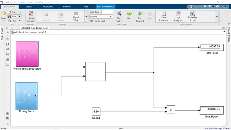
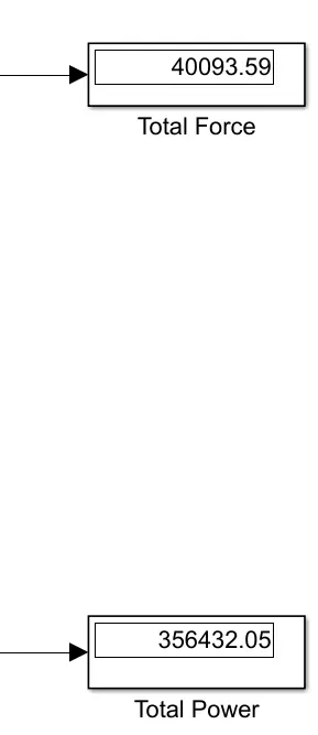
* so, if we observe the above image we can see the output values in the display blocks for the both total force and the total power and there will be a slight variation in between the calculated values and the simulated values which is a very minor difference and it is negligable
* foe more clarity below i am attaching the image of the only display blocks for a clear output for the comparission of manual calculated values and simulated values
7(a).
here they asked me to design an electric powertrain with type of motor, it’s power rating, and energy requirement to fulfill aircraft towing application in Simulink
the many values are considered from the above calculations, now we wre calculating the energy required for the vehicle
Energy required :
Energy : power * time
From the above calculation the power calculated is
Power (P) : 356.41 Kw
Time is assumed as 20 min which is converted into hours as 0.33 hrs
Time (T) : 0.33 hrs
So, Energy : power * time
= 356.41 * 0.33
= 117.6 Kwh
So, the energy required for above calculated 20 min is 117.6 Kwh
Now lets calculate the input power of the towing vehicle. And the output power is considered from the above calculations and Considering the values of towing vehicle TBL280
Duty cycle : output power / input power
Input power is to be calculated based on the assumptions of motor specifications
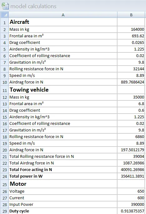
Input voltage : 650 V
Input current : 600 A
Now input power : input voltage * input current
= 650 * 600
= 390000 w
= 390 Kw
Total input power = 390 Kw
From the above calculation the duty cycle will be,
Duty cycle : output power / input power
= 356.41 / 390
= 0.91 = 91%
Duty cycle = 91%
Duty cycle required for towing vehicle TBL280 is 91%
Now lets tabulate the whole assumed parameters of the system
|
Parameter |
Values |
|
Aircraft |
|
|
Mass |
1640000 kg |
|
Height |
15.80 m |
|
Width |
43.90 m |
|
Air density |
1.225 kg/m3 |
|
Drag coefficient |
0.0265 |
|
Towing vehicle |
|
|
Mass |
35000 kg |
|
Height |
2 m |
|
Width |
3.4 m |
|
Tyre size |
0.5588 m |
|
Drag coefficient |
0.6 |
|
Air density |
1.225 kg/m3 |
|
Speed |
8.89 m/s |
|
Coefficient of rolling resistance |
0.02 |
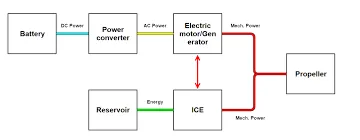
below image represents the SIMULINK model which is taken from the reference of DC7 motor example in the MATLAB
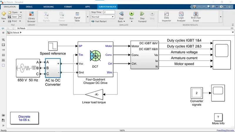
* the above model is taken from the reference of the dc7 motor example and modified according to the calculated parameters
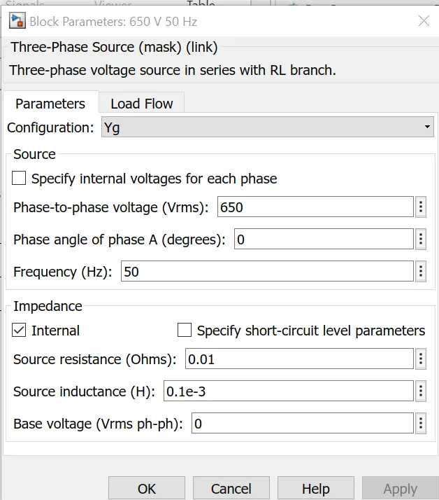
* if we observe the voltage is taken as 650v in the calculations and the input voltage in the model is also modified according to the calculations
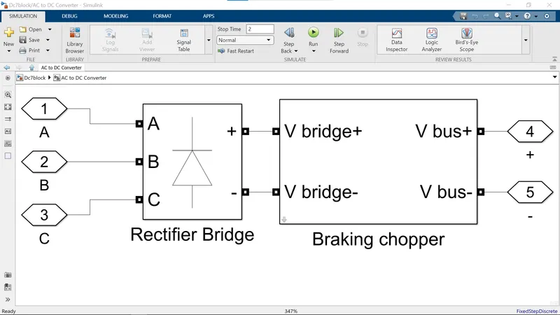
* here the AC-DC converter is used in the model and the above image represents the subsystem for the AC-DC converter block and it is needed because the moter taken is DC moter and the input giving is AC so it converts AC to DC and fed to the motor
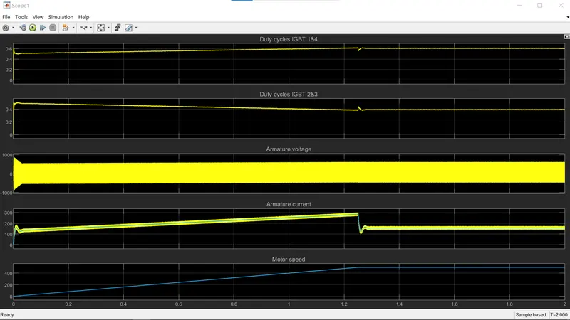
* if we observe the scope the graphs are plotted for duty cycle of IGBT 1&4, duty cycle of IGBT 2&3, armature current, armature voltage, and motor speed
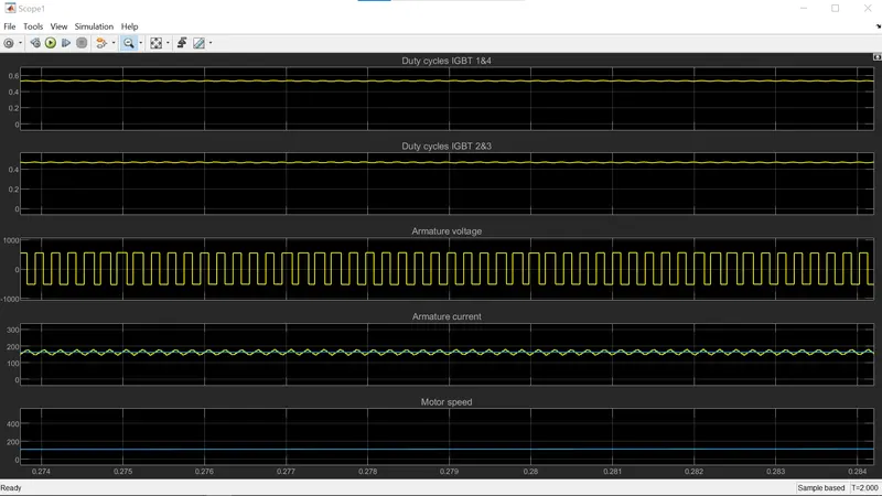
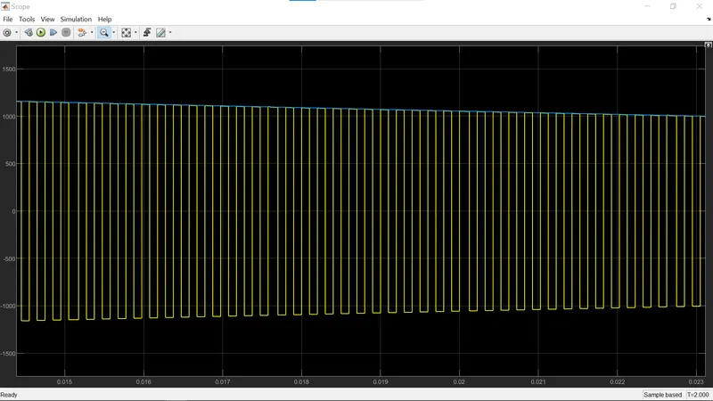
* for more understanding the scope results are zoomed and attached of the duty cycles and armature current, armature voltage, and motor speed
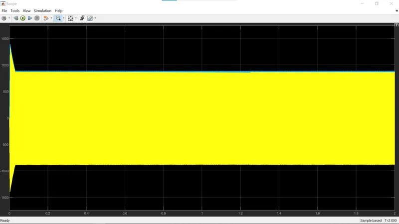
* the above graph output represents the scope of converter signals and it is related to the converter unit in the model and for more calirty the scope results are zoomed and attached in the below image
7(b)
the calculated values are attached in the excel sheet and the below the image is attached of the calculated sheet
Note :
below i am attaching the SIMULINK (.SLX) files of the above explained models and the EXCEL sheet of the calculated parameters
Thank you;
B. V. N. SANDEEP.