Project-1: Powertrain for aircraft in runways
"Project-1: Powertrain for aircraft in runways"
Aim & Objective:
Part A:
1. To search and list out the total weight of various types of aircrafts.
2. To find out that is there any difference between ground speed and air speed?
3. To justify why is it not recommended to use aircraft engine power to move it on the ground at Airport?
4. To find how an aircraft is pushed to runway when its ready to take off?
5. To learn about take off power, tyre design, rolling resistance, tyre pressure, brake forces when landing.
Part B:
6. A. To calculate the force and power required to push/pull an aircraft by a towing vehicle, With necessary assumptions.
B. To develop the model for the calculated force and power using Simulink.
7. A. To design an electric powertrain with a type of motor, it’s power rating, and energy required to fulfill aircraft towing application in Simulink. Estimate the duty cycle range to control the aircraft speed from zero to highest. Make all required assumptions. Prepare a table of assumed parameters. Draw a block diagram of the powertrain.
(Hint: DC7 Block)
B. To also, design the parameters in an excel sheet.
Part A:
Q1). Search and list out the total weight of various types of aircrafts.
The weight of the aircraft is needed to be calculated by the pilot for every flight to ensure the aircraft remains within weight limitations set by the manufacturer. These limitations are to ensure the aircraft is able to perform and recover from all flight maneuvers and withstand structural loading.
Typical Airplane Weights
Below is a table of some of the most common aircraft flying around our skies today:
| Aircraft | Empty Weight | Max Fuel Weight | Max Cargo Weight | Max Gross Takeoff Weight |
|---|---|---|---|---|
| Antanov AN-225 | 628,000 lbs 285,000 kg |
661,400 lbs 300,000 kg |
417,000 lbs 190,000 kg |
1,411,000 lbs 640,000 kg |
| Airbus A380-800 | 611,000 lbs 277,000 kg |
560,000 lbs 254,000 kg |
185,000 lbs 84,000 kg |
1,268,000 lbs 575,000 kg |
| Boeing 747-800 | 485,300 lbs 220,100 kg |
427,400 lbs 194,000 kg |
295,000 lbs 134,000 kg |
987,000 lbs 447,700 kg |
| Airbus A340-500 | 370,000 lbs 168,000 kg |
386,300 lbs 175,000 kg |
119,000 lbs 54,000 kg |
820,000 lbs 372,000 kg |
| Boeing 777-300ER | 370,000 lbs 168,000 kg | 320,800 lbs 145,500 kg | 148,000 lbs 67,100 kg |
776,000 lbs 352,000 kg |
| Boeing 787-10 | 299,000 lbs 135,500 kg | 223,500 lbs 101,500 kg |
126,300 lbs 57,300 kg | 560,000 lbs 254,000 kg |
| Boeing 737-900 | 98,500 lbs 44,700 kg |
53,100 lbs 24,000 kg |
44,600 lbs 20,200 kg |
187,000 lbs 85,000 kg |
| Airbus A320-100 | 93,900 lbs 42,600 kg |
48,700 lbs 22,100 kg |
44,000 lbs 20,000 kg |
150,000 lbs 68,000 kg |
| Embraer 190 | 63,500 lbs 28,800 kg |
28,600 lbs 13,000 kg |
28,800 lbs 13,100 kg |
106,000 lbs 48,000 kg |
| Gulfstream G650 | 54,000 lbs 24,500 kg | 48,200 lbs 21,900 kg | 6,500 lbs 3,000 kg |
100,000 lbs 45,200 kg |
| Bombardier CRJ900 | 48,160 lbs 21,850 kg | 19,600 lbs 8,900 kg | 6,075 lbs 2,760 kg | 80,500 lbs 36,500 kg |
| Bombardier Q400 | 39,300 lbs 17,800 kg |
11,700 lbs 5,300 kg |
18,700 lbs 8,500 kg |
62,000 lbs 28,000 kg |
|
Learjet 75 |
13,900 lbs 6,300 kg | 6,060 lbs 2,750 kg |
2,900 lbs 1,300 kg |
21,500 lbs 9,700 kg |
| Cessna Citation CJ4 | 10,300 lbs 4,700 kg | 5,800 lbs 2,650 kg |
2,200 lbs 1,000 kg | 17,200 lbs 7,800 kg |
| Beechcraft King Air B100 | 7,100 lbs 3,200 kg | 3,200 lbs 1,450 kg |
4,150 lbs 1,900 kg |
12,000 lbs 5,400 kg |
| Diamond DA50 RG | 3,200 lbs 1,450 kg |
340 lbs 155 lbs |
1,250 lbs 560 kg |
4,400 lbs 2,000 kg |
| Beechcraft Bonaza G36 | 2,500 lbs 1,150 kg | 450 lbs 200 kg |
850 lbs 385 kg |
3,660 lbs 1,660 kg |
| Cessna 206H | 2,200 lbs 990 kg |
520 lbs 235 kg |
1,150 lbs 520 kg |
3,600 lbs 1,630 kg |
| Sirrus SR22 | 2,250 lbs 1,000 kg | 485 lbs 220 kg |
950 lbs 430 kg |
3,600 lbs 1,630 kg |
| Cessna 172R | 1,700 lbs 770 kg |
380 lbs 170 kg |
560 lbs 255 kg |
2,425 lbs 1,100 kg |
Aircraft Empty Weight (AEW):
This is sometimes referred to as OEW – Operating Empty Weight and it is the weight of the aircraft with all its equipment on board but no fuel, no passengers or no cargo.
Think of this like the aircraft has just come out of the factory and is sitting waiting to be fueled up for delivery to the customer.
Aircraft Maximum Gross Takeoff Weight (MGTW):
This is the maximum permissible weight the aircraft can weigh as it lifts off the ground at takeoff. This includes the aircraft’s empty weight, the fuel, the crew, the passengers, and all the cargo.
This weight limit is set by the manufacturer and is gospel. Many aircraft accidents have been caused by an aircraft being overweight and the pilot/s have not had enough power or maneuverability to prevent the accident.
Aircraft Useful Load:
This is the weight that a pilot can place in the aircraft. Take the MGTW figure and subtract the AEW and this is the total useful load that can be placed into the aircraft. This is the fuel, crew, passengers, and cargo. The bigger the load, the more useful the aircraft can be to its customers!
How Fuel, Passengers & Cargo Affect Aircraft Weight:
Each item of weight added to the aircraft has to be accounted for and some items can be left off the flight and others not so much. There are several scenarios we can look at, and for these examples, I will use the Astar helicopter I fly, as it is really easy for me to work out the numbers:
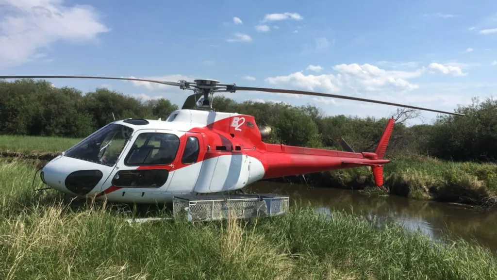
AS350 Astar B2 Helicopter Specs:
Aircraft Empty Weight: 3000 lbs
Aircraft Maximum Gross Weight: 4961 lbs
Aircraft Maximum Fuel Weight: 1000 lbs
Aircraft Useful Load: 1961 lbs
Scenario #1: All Fuel & No Cargo or Passengers:
This would be on a flight when I have finished a job and I am returning back to the hanger after dropping off the passengers and their cargo:
- Aircraft Empty Weight: 3000 lbs
- Pilot Weight: 185 lbs
- Aircraft Full Fuel Weight: 1000 lbs
- Total Aircraft Weight = 4,185 lbs (776 lbs under MGTW)
Scenario #2: Full Passengers & 200 lbs of Cargo:
This would be on a flight when I am starting a job in the morning and I am departing from the hanger with a work crew and their tools:
- Aircraft Empty Weight: 3000 lbs
- Pilot Weight: 185 lbs
- Passengers Weight: 950 lbs
- Cargo Weight: 200 lbs
- Aircraft Full Fuel Weight: 1000 lbs
- Total Aircraft Weight = 5,335 lbs (374 lbs OVER MGTW)
In this scenario, I would need to offload weight. The 3 variables are:-
- Passengers
- Cargo
- Fuel
Usually, the passengers and their cargo need to go as they are the ones doing the work, so fuel has to be reduced. Instead of filling the aircraft fuel tank up to 100%, I can only fill it to around 60% to keep the aircraft under its MGTW.
Q2). Is there any difference between ground speed and air speed?
One of the most confusing concepts for young scientists is the relative velocity between objects. Aerodynamic forces are generated by an object moving through a fluid (liquid or gas). A fixed object in a static fluid does not generate aerodynamic forces. Hot air balloons "lift" because of buoyancy forces and some aircraft like the Harrier use thrust to "lift" the vehicle, but these are not examples of aerodynamic lift. To generate lift, an object must move through the air, or air must move past the object. Aerodynamic lift depends on the square of the velocity between the object and the air. Now things get confusing because not only can the object be moved through the air, but the air itself can move. To properly define the relative velocity, it is necessary to pick a fixed reference point and measure velocities relative to the fixed point. In this slide, the reference point is fixed to the ground, but it could just as easily be fixed to the aircraft itself. It is important to understand the relationships of wind speed to ground speed and airspeed.
Wind Speed:
For a reference point picked on the ground, the air moves relative to the reference point at the wind speed. Notice that the wind speed is a vector quantity and has both a magnitude and a direction. Direction is important. A 20 mph wind from the west is different from a 20 mph wind from the east. The wind has components in all three primary directions (north-south, east-west, and up-down).
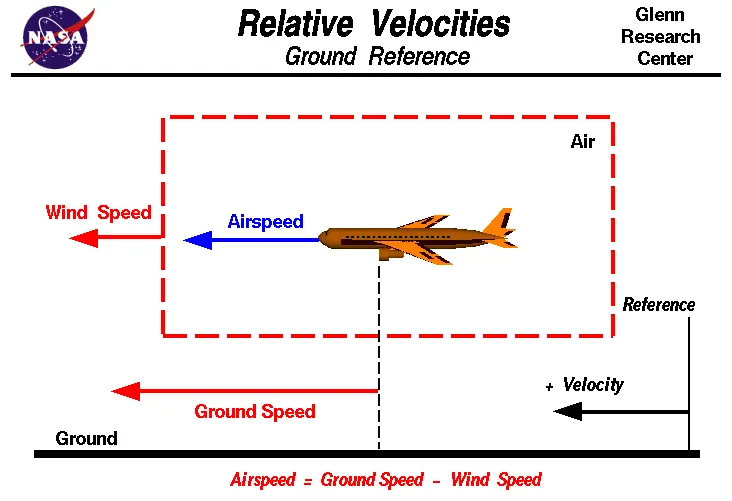
In this figure, we are considering only velocities along the aircraft's flight path. A positive velocity is defined to be in the direction of the aircraft's motion. We are neglecting cross winds, which occur perpendicular to the flight path but parallel to the ground, and updrafts and downdrafts, which occur perpendicular to the ground.
Ground Speed:
For a reference point picked on the ground, the aircraft moves relative to the reference point at the ground speed. Ground speed is also a vector quantity so a comparison of the ground speed to the wind speed must be done according to rules for vector comparisons.
Airspeed:
The important quantity in the generation of lift is the relative velocity between the object and the air, which is called the airspeed. Airspeed cannot be directly measured from a ground position, but must be computed from the ground speed and the wind speed. Airspeed is the vector difference between the ground speed and the wind speed.
Airspeed = Ground Speed - Wind Speed
On a perfectly still day, the airspeed is equal to the ground speed. But if the wind is blowing in the same direction that the aircraft is moving, the airspeed will be less than the ground speed.
For Example,
Suppose we had an airplane that could take off on a windless day at 100 mph (liftoff airspeed is 100 mph). We are at an airport with an east-west runway that is 1 mile long. The wind is blowing 20 mph towards the west and the airplane takes off going east. The wind is blowing towards the aircraft which we call a headwind. Since we have defined a positive velocity to be in the direction of the aircraft's motion, a headwind is a negative velocity. While the plane is sitting still on the runway, it has a ground speed of 0 and an airspeed of 20 mph:
Airspeed = Ground Speed (0) - Wind Speed (-20) = 20 mph
The airplane starts its take off roll and has a constant acceleration a. From Newton's second law of motion, the ground speed V at any time t is:
V = a * t
and the distance d down the runway at any time is:
d = 1/2 * a * t^2
For a fixed length runway, this specifies the time to be used in the velocity equation. Let's assume that at 5000 feet down the runway, the velocity is 80 mph. Then the airspeed is given by
Airspeed = Ground Speed (80) - Wind Speed (-20) = 100 mph
and the airplane begins to fly. Now another pilot, with exactly the same airplane decides to take off to the west. The wind is now in the same direction as the motion and this is called a tailwind. The sign on the wind speed is now positive, not negative as with the headwind. The acceleration along the ground is the same, so at 5000 feet down the runway, the ground speed is again 80 mph. The airspeed is then given by:
Airspeed = Ground Speed (80) - Wind Speed (20) = 60 mph
Hence, There is a difference between ground speed and air speed.
Q3). Why is it not recommended to use aircraft engine power to move it on the ground at Airport?
For movement on the ground, the aircraft uses its own engine power, which is called taxiing.
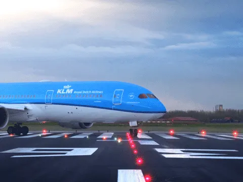
- Generally, most of the airplanes can move themselves in reverse manner by making use of reverse thrust technology. But in most of the practical cases, it is not possible because when airplanes start using reverse thrust it will consume lots of fuels as well as causes lots of noise, and also be hazardous for the people working nearby.
- Another reason for not using reverse thrust is that the jet blast might cause damage to the terminal building or equipment. Since the engine is also close to the ground it will blow off the sand and debris forward and then suck them into the engine, causing damage to the engine.
- Therefore, there are pushback trucks in the airport. A pushback truck lifts the front wheel of the aircraft, their role in most airports is to move the aircraft away from the parking spot onto the taxiways, which is called towing.
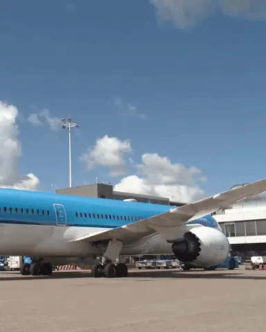
Q4). How an aircraft is pushed to runway when it's ready to take off?
In aviation, pushback is an airport procedure during which an aircraft is pushed backward away from its parking position, usually at an airport gate by an external power. Pushbacks are carried out by special, low-profile vehicles called pushback tractors or tugs.
Although many aircraft are capable of moving themselves backward on the ground using reverse thrust (a procedure referred to as a powerback), the resulting jet blast or prop wash would cause increased noise, damage to the terminal building or equipment, and hurt airport staff due to high-speed debris. This debris would also be sucked into the engine, as it is in normal use, and cause excessive wear - a major cause of wear on aircraft engines is during ground use. A pushback is therefore the preferred method when ground-handling aircraft.
Pushbacks at busy aerodromes are usually subject to ground control clearance to facilitate ground movement on taxiways. Once clearance is obtained, the pilot will communicate with the tractor driver (or a ground handler walking alongside the aircraft in some cases) to start the pushback. To communicate, a headset may be connected near the nose gear.
Since the pilots cannot see what is behind the aircraft, steering is done by the pushback tractor driver and not by the pilots. Depending on the aircraft type and airline procedure, a bypass pin may be temporarily installed into the nose gear to disconnect it from the aircraft's normal steering mechanism.
Once the pushback is completed, the towbar is disconnected, and any bypass pin is removed. The ground handler will show the bypass pin to the pilots to make it clear that it has been removed. The pushback is then complete, and the aircraft can taxi forward under its own power.
Q5). Learn about take off power, tyre design, rolling resistance, tyre pressure, brake forces when landing.
`rArr` Take off power:
Takeoff is the phase of flight in which an aerospace vehicle leaves the ground and becomes airborne. For aircraft traveling vertically, this is known as liftoff.
For aircraft that take off horizontally, this usually involves starting with a transition from moving along the ground on a runway.
For light aircraft, usually full power is used during takeoff. Large transport category (airliner) aircraft may use a reduced power for takeoff, where less than full power is applied in order to prolong engine life, reduce maintenance costs and reduce noise emissions. In some emergency cases, the power used can then be increased to increase the aircraft's performance. Before takeoff, the engines, particularly piston engines, are routinely run up at high power to check for engine-related problems.
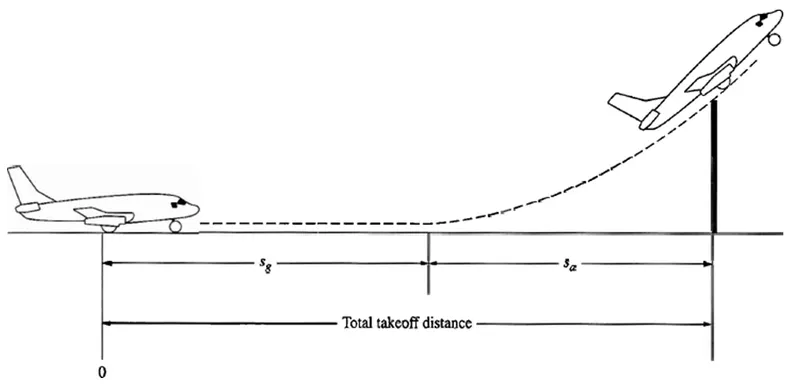
An airplane is motionless at the end of a runway. This is denoted by location O. The pilot releases the brakes and pushes the throttle to maximum takeoff power, and the airplane accelerates down the runway. At some distance from its starting point, the airplane lifts into the air. The distance the airplane cover along the runway before it lifts into the air is called the ground roll (sg). The total takeoff distance also includes the extra distance covered over the ground after the airplane is airborne but before it clears an obstacle of 50 ft for military aircraft and 35 ft for commercial aircraft. This is denoted by sa. The sum of sg and sa is the total takeoff distance.
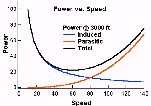
The above figure shows the power curves for induced power, parasitic power, and total power which is the sum of induced power and parasitic power. Again, the induced power goes as one over the speed and the parasitic power goes as the speed cubed. At low speed, the power requirements of flight are dominated by the induced power. The slower one flies the less air is diverted and thus the angle of attack must be increased to maintain lift. Pilots practice flying on the "backside of the power curve" so that they recognize that the angle of attack and the power required to stay in the air at very low speeds are considerable.
For aircraft that take off horizontally, this usually involves starting with a transition from moving along the ground on a runway. For balloons, helicopters, and some specialized fixed-wing aircraft (VTOL aircraft such as the Harrier and the Bell Boeing V22 Osprey), no runway is needed.
- Horizontal Takeoff:
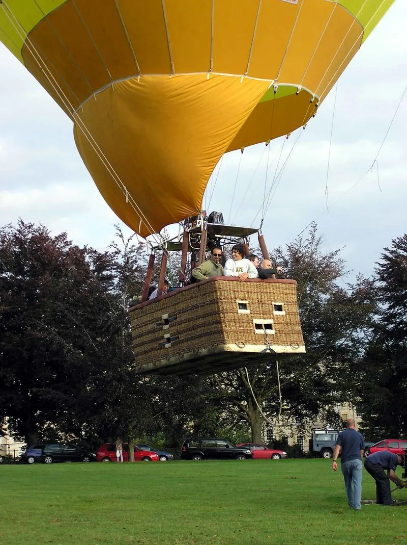
Takeoff of a hot air balloon
For light aircraft, usually full power is used during takeoff. Large transport category (airliner) aircraft may use a reduced power for takeoff, where less than full power is applied in order to prolong engine life, reduce maintenance costs and reduce noise emissions. In some emergency cases, the power used can then be increased to increase the aircraft's performance. Before takeoff, the engines, particularly piston engines, are routinely run up at high power to check for engine-related problems. The aircraft is permitted to accelerate to rotation speed (often referred to as Vr). The term rotation is used because the aircraft pivots around the axis of its main landing gear while still on the ground, usually because of gentle manipulation of the flight controls to make or facilitate this change in aircraft attitude (once proper air displacement occurs under/over the wings, an aircraft will lift off on its own; controls are to ease that in).
The nose is raised to a nominal 5°–15° nose up pitch attitude to increase lift from the wings and effect liftoff. For most aircraft, attempting a takeoff without a pitch-up would require cruise speeds while still on the runway.
- Vertical Takeoff:
Vertical takeoff refers to aircraft or rockets that take off in a vertical trajectory. Vertical takeoff eliminates the need for airfields. Most vertical takeoff aircraft are also able to land horizontally, but there were certain rocket-powered aircraft of the Luftwaffe that only took off vertically, landing in other ways. The Bachem Ba 349 Natter landed under a parachute after having taken off vertically. Other late projects developed in Nazi Germany, such as the Heinkel P.1077 Julia or the Focke-Wulf Volksj`ddota`ger 2, climbed to their ceiling at a nearly vertical angle and landed later on a skid.
VTOL:
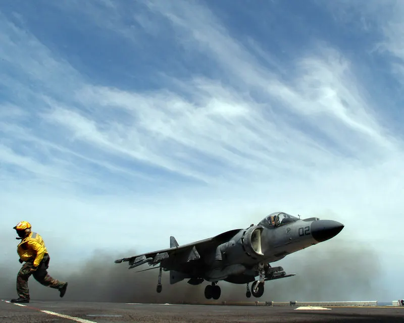
The Harrier Jump Jet, a VTOL aircraft
Vertical take-off and landing (VTOL) aircraft include fixed-wing aircraft that can hover, take off and land vertically as well as helicopters and other aircraft with powered rotors, such as tiltrotors. Some VTOL aircraft can operate in other modes as well, such as CTOL (conventional take-off and landing), STO (short take-off and landing), and/or STOVL (short take-off and vertical landing). Others, such as some helicopters, can only operate by VTOL, due to the aircraft lacking landing gear that can handle horizontal motion. VTOL is a subset of V/STOL (vertical and/or short take-off and landing).
Besides the helicopter, there are two types of VTOL aircraft in military service: craft using a tiltrotor, such as the Bell Boeing V-22 Osprey, and some aircraft using directed jet thrust such as the Harrier family.
`rArr`Tyre design:
An aircraft tyre is designed to withstand extremely heavy loads while landing, take off, taxing, and parking. The number of wheels required for aircraft increases with the weight of the aircraft, as the weight of the aeroplane needs to be distributed more evenly. For example - A Boeing 737NG & 737MAX uses 6 wheels, Boeing 787 uses 10 wheels, Boeing 777 uses 14 wheels and Airbus A380 uses 22 wheels.
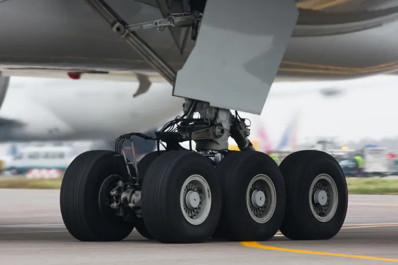
Fig: Tires on the wheels of a bogie on a Boeing 777
Aircraft tires also include fusible plugs (which are assembled on the inside of the wheels), designed to melt at a certain temperature. Tires often overheat if maximum braking is applied during an aborted takeoff or an emergency landing. The fuses provide a safer failure mode that prevents tire explosions by deflating in a controlled manner, thus minimizing damage to aircraft and objects in the surrounding environment.
Designing aircraft tires is a very intense undertaking. Carcass plies are used to form the tire. They are sometimes called casing plies. An aircraft tyre is constructed for the purpose it serves.
- They support the weight of an aircraft while it is on the ground.
- It also provides the necessary traction for braking and stopping of an aeroplane.
- Tyre also helps to absorb the shock of landing and provide cushioning the roughness of takeoff, roll-out, and taxi operations.
Once an aircraft manufacturer goes to the tire manufacturer with the size and weight requirements, the tire manufacturer begins the process of designing a tire that meets the needs of the aircraft manufacturer as well as all regulatory requirements — including foreign regulations in many cases.
Engineers are challenged with designing tires with cool running, heat-resistant materials while simultaneously exceeding tire service requirements.
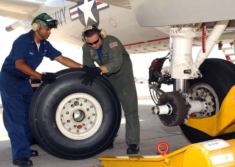
Fig: Changing a wheel on a Lockheed P-3 Orion aircraft
Two types of tires are used in aircraft applications — bias-ply tires and radial tires. Although both types of tires share some similarities in design, there are differences that need to be noted.
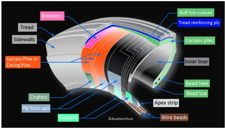
Tread: The tread is made of rubber mixed with other additives to obtain the desired level of toughness, durability, and resistance to wear. The tread pattern is designed to aircraft operational requirements, with the ribbed tread design used widely due to its good traction under varying runway conditions.
Sidewall: The sidewall is a protective layer of rubber that covers the outer casing ply. It extends from the tread edge to the bead area.
Tread Reinforcing Ply: One or more layers of fabric that strengthens and stabilizes the tread area for high-speed operation. It also serves as a reference for the buffing process when tires are retreaded.
Buff Line Cushion: The buff line cushion is made of rubber compound to enhance the adhesion between the tread reinforcing ply and the breakers or casing plies. It is of sufficient thickness to allow for the removal of the old tread when the tire is retreaded.
Breakers: Breakers are reinforcing plies of rubber-coated fabric placed under the buff line cushion to protect casing plies and strengthen and stabilize the tread area. They are considered an integral part of the casing construction.
Casing Plies: Alternate layers of rubber-coated fabric (running at opposite angles to one another) provide the strength of the tire.
Wire Beads: Hoops of high tensile strength steel wire that anchor the casing plies and provide a firm mounting surface on the wheel. The outer edge of the bead that fits against the wheel flange is called the bead heel. The inner bead edge is called the bead toe.
Apex Strip: A wedge of rubber affixed to the top of the bead bundle.
Bead toe: It is the inner edge of the bead.
Bead heel: It is the outer edge of the heel.
Flippers: Layers of rubberized fabric that help anchor the bead wires to the casing and improve the durability of the tire.
Ply Turnups: The casing plies are anchored by wrapping them around the wire beads, thus forming the ply turnups.
Chafer: A protective layer of rubber and/or fabric located between the casing plies and wheel to minimize chafing.
Liner: In tubeless tires, the liner is a layer of low permeability rubber that acts as a built-in tube and restricts gas from diffusing into the casing plies. In tube-type tires, a thinner liner is used to prevent tube chafing against the inside ply.
Caroass Plies: Layers of rubber-coated fabric piles which have the cords running from bead to bead. These provide the tire with strength in the sidewall area.
Tubeless tyres are more advantageous over tube-type. There is no longer the use of tube-type tyre in recent aviation. Nowadays all airliners are using tubeless tyres. Tubeless that are meant to be used without a tube has the word TUBELESS on the sidewall of the tyre.
Aircraft tyres must have an approved speed and load rating and have sufficient clearance when retracted through landing gear to allow for tyre growth. Tyre growth is the increase in the size of the tyre due to centrifugal forces at high speed.
Retreading – Retreading is methods of restoring a worn tyre by renewing the tread area or by renewing the tread area plus one or both sidewalls. Repairs are included in the tyre retreading process.
Load Rating – Load rating is the maximum permissible load at a specified inflation pressure.
Ply Rating – Ply Rating is used to identify the maximum recommended load rating and inflation pressure for a specified tyre. It is an index of tyre strength.
Speed Rating – The speed rating is the maximum takeoff speed to which the tyre has been tested.
Skid Depth – Skid depth is the distance between the tread surface and the deepest groove as measured in the mould.
Today’s tyres are conductive. Aircraft tyres are manufactured with tread rubber with conducting compounds to permit earthing of static charges. In early days when tyres were not sufficiently conductive, aircraft used to have a conductive strip hanging down from the axle of the landing gear. Upon landing, this strip would be the first part of the aircraft to touch the earth. This discharges any static electricity accumulated on the outer surfaces of the aircraft.
`rArr`Rolling Resistance:
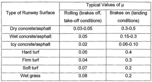
- In addition to the familiar forces like thrust, weight, lift, drag there is a rolling resistance force FR caused by friction between tyre and ground. When aircraft is towing or taxiing to push it into the runway or when takeoff roll is happening, the rolling resistance force act against the traction force of the aircraft.
- This rolling resistance force depends on many factors like surface of the road, roughness of the road, dry or wet condition of the road, tyre pressure, tyre material, tyre temperature, thread pattern of the tyre etc, which determines the rolling resistance force.
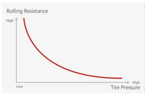
- The rolling resistance coefficient is denoted by `mu_(rr)`. The values vary with speed. Tire pressure increases its value decreases need to carefully choose value as per typical cases under consideration.
Rolling Resistance force `(F_(rr))` = `mu_(rr)`x m x g
Where,
`mu_(rr)`= Rolling resistance coefficent
m = Total mass of the aircraft in kg
g = Gravitational constant i.e, 9.8 m/`s^2`
`rArr`Tyre Pressure:
Aircraft tires may be tube-type or tubeless. Tubeless tyres are more advantageous over tube-type. There is no longer the use of tube-type tyre in recent aviation. Nowadays all airliners are using tubeless tyres. Tubeless that are meant to be used without a tube has the word TUBELESS on the sidewall of the tyre.
Tyre pressure varies from plane to plane.
- The tires do not use the typical compressed air we would use from a fuel station supply or a home air compressor.
- Aviation tires are made of a much stronger compound than what we use for the auto industry and in fact, they use nitrogen gas to inflate the tires, as opposed to compressed air.
- This provides additional strength to the tires in general, to support the tremendous weight they carry moving the plane or on take-off and for landing.
- The average pressure they run in the tires is between 200-220 PSI, it again depends on the model aircraft(Automobile run 30-40 PSI on average).
- Tires are required to replace after every 300 or so cycles. A cycle represents 1 for a landing and 1 for a lift-off. Every time a plane lands and departs, this is considered 2 cycles.
- When the tire pressure becomes too low then values of rolling resistance increase too much.
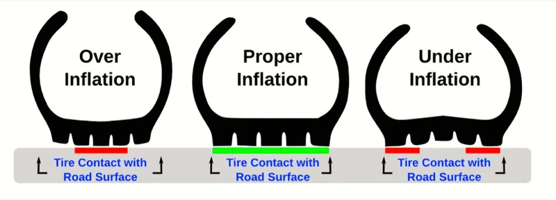
The requirement that an inert gas, such as nitrogen, be used instead of air for inflation of tires on certain transport category airplanes was prompted by at least three cases in which the oxygen in air-filled tires had combined with volatile gases given off by a severely overheated tire and exploded upon reaching autoignition temperature. The use of inert gas for tire inflation eliminates the possibility of a tire explosion.
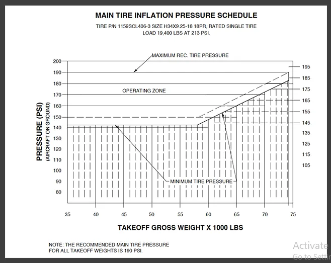
Fig: G450 Main tire inflation schedule
According to U.S. Federal Aviation Administration(FAA) Technical Standard Order TSO-C62c, the maximum allowable tire pressure loss is 5% per day.
Fig: Daily measuring tyre pressure
Example:
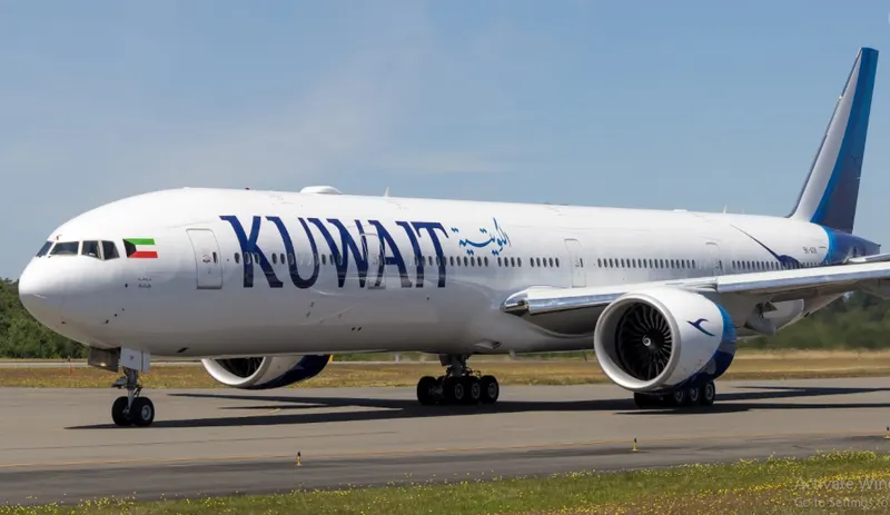
Fig: Boeing 777
A Boeing 777 is fully loaded weighs around 700,000 pounds and has fourteen tires. Therefore, if each of those tires is reacting roughly the same force, then that is 50,000 pounds per tire. the tire pressure is 200 psi. Therefore there should be 250 square inches of surface contact area for each tire with the ground (250 * 200 = 50,000).
`rArr`Brake forces when landing :
Even though airplanes have become one of the most convenient ways of traveling in the modern world, there are very few people who are aware of how it operates. As we all know, when a plane is about to land, it is at high speed, typically 16 mph. The question here is that how can a plane de-accelerate safely, even though it is coming at such a high speed?
To understand the answer to this question, we have to understand how braking works, not just in an airplane, but in any vehicle which has wheels. As we have already mentioned above how the braking process exerts torque on the wheels due to which friction is produced. As a result, friction is produced with the ground, and it loses kinetic energy, and hence, the vehicle stops.
But the thing about friction is that it depends entirely on the weight of the vehicle. In the case of the airplane, when it is landing, the aerodynamic lift renders the weight of the plane zero, and hence, the brakes on the wheels are pretty much inefficient to stop the plane. That is why the plane needs to find other ways to stop until both the aerodynamic lift and the speed has reached a sufficient stage. Modern aircraft use several different braking systems to do this:
Wing Spoilers:
Many airplanes use wing spoilers to assist with braking when landing. Not to be confused with ailerons, spoilers are extendable flaps on the ends of an airplane’s wings. Pilots can raise the spoilers to decelerate the airplane as it approaches the runway. And even while on the runway, pilots will typically leave the wing spoilers raised. Raised wing spoilers create the drag, which essentially slows down the airplane so that it’s able to brake more quickly.
Aircraft Disc Brakes:
In addition to wing spoilers, airplanes use disc brakes. Airplane disc brakes are similar to the braking system in automobiles. They consist of a pair of calipers that, when engaged, squeeze pads against the rotors of an airplane’s landing gear.
Disc brakes are designed to remain static at all times. In other words, they don’t rotate with the wheels of an airplane’s landing gear. As the wheels turn, the disc brakes will remain static and stationary. They are a vital component of an airplane’s braking system because they are designed to apply pressure to the airplane’s wheels. Disc brakes will squeeze the wheels, thereby slowing down the speed at which they spin. In turn, this reduces the speed of the airplane so that it can come to a complete stop on the runway.
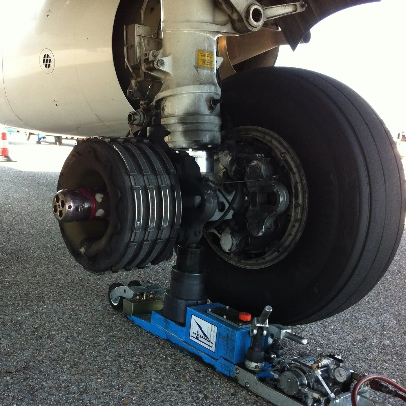
Fig: A brake assembly on a Boeing 737NG main landing gear
Reverse Thrust:
Many jet airplanes use reverse thrust to assist with braking during landings. Reverse thrust is a feature in jet engine airplanes that, as the name suggests, involves the reversal of the engines’ thrust. When flying, the thrust is projected out the rear of an airplane’s engines. When landing, however, pilots may use the reverse thrust feature. Reverse thrust changes the direction of the engines’ thrust. Rather than projecting out the rear, the thrust will be projected out the front. This reversal of thrust provides deceleration that allows airplanes to slow down more quickly when landing.
Fig: Boeing 747-400 Reverse Thrust Spray
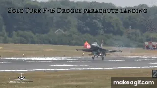
Drogue Parachute:
used by several former and current military and civilian aircraft (examples include the American B-52 and the soviet Tu-134 and Tu-144) and in the Space Shuttle.
Part B:
Q6). A. With necessary assumptions, calculate the force and power required to push/pull an aircraft by a towing vehicle.
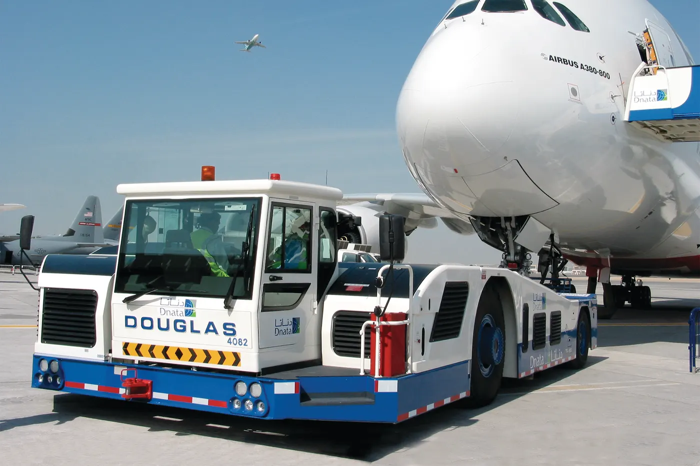
In this study, we want to calculate the force and power required to push and pull an aircraft by towing vehicle so we take one of the towing vehicle model and airbus model on the website and consider the data for our calculation.
DOUGLAS TOWBARLESS AIRCRAFT TRACTOR: Model: TBL 280Mk4
The Douglas Tugmaster type TBL- 280 Mk4 towbarless aircraft handling tractor has been designed primarily for pushback, inter-gate towing, and longer distance maintenance towing operations at higher speeds with the following aircraft: -
Embraer: ERJ 190/195
McDonnell Douglas: DC9/MD80/MD90
Boeing: B717, B737, B727, B757, B767, B787 and B777.
Airbus: A318/A319/A320/A321, A310/A300, A330 and A340-200/300
Boeing: DC10/MD11
Lockheed: L 1011
- Maximum cradle lifting capacity = 35,000 kgs(Aircraft nose wheel weight).
- Length (Excluding Coupler) = 333” (8,470 mm) = 8.47m
- Width = 134” (3,400 mm) = 3.4m
- Wheel Base = 173” (4,400 mm) = 4.4m
- Height = 79" (2,000 mm) = 2m
- Tyre Size = R 22.5 = 571.5mm = 0.5715m
- Maximum Governed Speed = 20 mph (32 kph)
The coefficient of friction depends on the objects that are causing friction. The value is usually between 0 and 1 but can be greater than 1. A value of 0 means there is no friction at all between the objects. A value of 1 means the frictional force is equal to the normal force. It is a misconception that the coefficient of friction is limited to values between 0 and 1. A coefficient of friction that is more than 1 just means that the frictional force is stronger than the normal force.
Coefficient of rolling resistance(`mu_(rr)`) = 0.02 (Truck tyre in asphalt concrete road)
Aircraft Model:
We are taking an aircraft model as Airbus A310 as considered as pushback operation. The advanced technologies of A310 and some specifications are given below,
The A310 helped pioneer the use of composites in commercial jetliners, with its vertical stabiliser built with carbon-fibre materials that offer significant weight savings over conventional metallic structures. Other major applications of composites on the A310 include floor struts and panels, spoilers and main landing gear doors.
- Standard or Higher Gross Weight = 164000 kg
- Height = 15.80 m
- Width = 43.90 m
- Drag Coefficent (`C_d`) = 0.02685
To Find:
The total force and power required to push/pull an aircraft by the towing vehicle.
Formula used:
Total Force (F) = `F_(rr)+F_(ad)`
Rolling resistance Force (`F_(rr)`) = `mu_(rr).m.g`
Drag Force (`F_(ad)`) = `1/2.rho.A.C_d.v^2`
Solution:
In the first step, we have to find out the rolling resistance force and air drag force for both towing vehicle and airbus to obtain the force and power value during the towing process,
To find rolling resistance force:
For Aircraft :
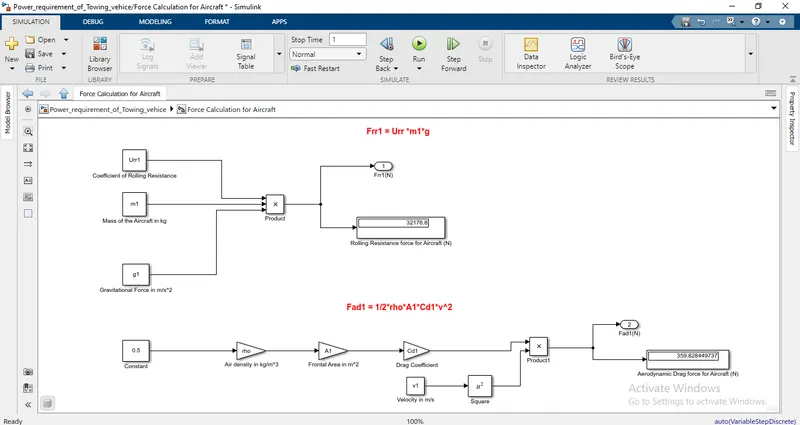
Rolling resistance force (`F_(rr_1)`) = `mu_(rr).m_1.g`
Where,
`mu_(rr)` = Coefficient of rolling resistance of aircraft = 0.02
`m_1` = mass of the aircraft = 164000 kg
g = gravitational force = 9.8 m/`s^2`
`:.`(`F_(rr_1)`) = 0.02 x 164000 x 9.81
= 32176.80 N
For Towing Vehicle:
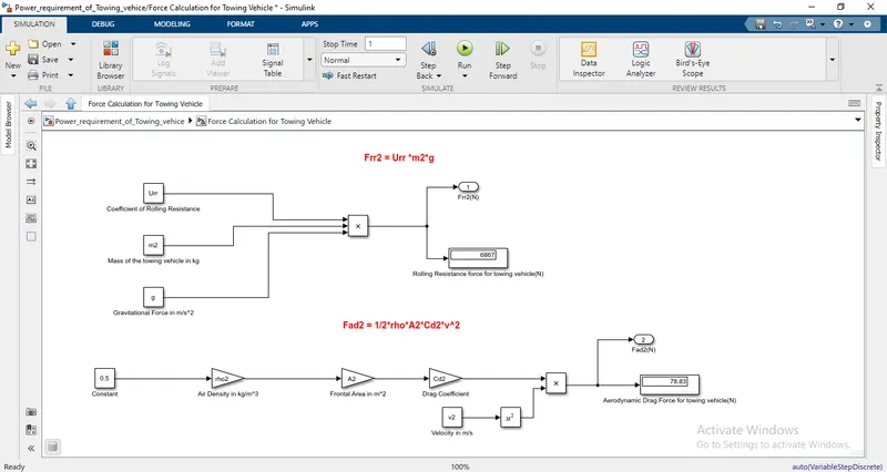
Rolling resistance force (`F_(rr_2)`) = `mu_(rr).m_2.g`
Where,
`mu_(rr)` = Coefficient of rolling resistance of towing vehicle = 0.02
`m_2` = mass of the towing vehicle = 35000 kg
g = gravitational force = 9.8 m/`s^2`
`:.(F_(rr_2))` = 0.02 x 35000 x 9.81
= 6909 N
So, the Rolling resistance force (`F_(rr)`) = `F_(rr_1)+F_(rr_2)`
= 32176.80 + 6909
= 39085.80 N
To find Air drag force:
The Air Drag Force (`F_(ad)`) = `1/2.rho.A.C_d.v^2`
Where,
`rho` = Density of air
A = frontal area of the vehicle on which the air strikes
v = velocity of the vehicle
`C_d` = Drag Coefficient
For Aircraft :
Air Drag Force (`F_(ad_1)`) = `1/2*rho*A_1*C_(d_1)*v^2`
Where,
`rho` = 1.25 kg/`m^3`
`A_1` = Height of the airbus x Width of the airbus = 15.80 x 43.90 = 693.62 `m^2`
Assume that vehicle running at the speed of 20 kmph.
`:.` v = (20 x `5/18`) = 5.56 m/s
`C_(d_1)` = Drag Coefficient of aircraft = 0.02685
`:.` (`F_(ad_1)`) = `1/2` x 1.25 x 693.62 x 0.0265 x `(5.56)^2`
= 355.137 N
For Towing Vehicle:
Air Drag Force (`F_(ad_2)`) = `1/2.rho.A_2.C_(d_2).v^2`
Where,
`rho` = 1.25 kg/`m^3`
`A_2` = Height of the towing vehicle x Width of the towing vehicle = 2 x 3.4 = 6.8 `m^2`
Assume that vehicle running at the speed of 20 kmph.
`:.` v = (20 x `5/18`) = 5.56 m/s
`C_(d_2)` = Drag Coefficient of the towing vehice = 0.6
`:.` (`F_(ad_2)`) = `1/2` x 1.25 x 6.8 x 0.6 x `(5.56)^2`
= 78.82 N
So, the Air Drag Force (`F_(ad)`) = (`F_(ad_1)`) + (`F_(ad_2)`)
= 355.137 + 78.82
= 437.13 N
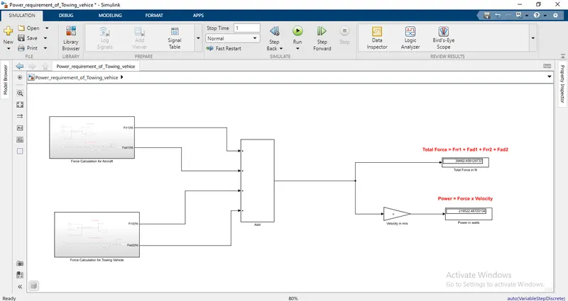
Now, the total force (F) = the Rolling resistance force (`F_(rr)`) + the Air Drag Force (`F_(ad)`)
= 39085.80 + 437.13
= 39522.93 N
Power required to push/pull the aircraft:
Power = Total Force x velocity
= 39522.93 x 5.56
= 219747.49 W
Therefore, Power = 219.74 kW
Q6). B. Develop the model for the calculated force and power using Simulink.
Force Calculation for Aircraft:
Force Calculation for Towing Vehicle:
Power requirement of Towing Vehice to push/pull the aircraft:
Model Explanation:
- Constant and gain blocks are used to feed the parameters such as mass, coefficient, and the other parameters.
- By using product block the resistive forces are calculated.
- By using the sum block the total forces are calculated.
- Lastly, the outputs are visualized by using display blocks.
Simulink Model Link: https://drive.google.com/file/d/1B1ShNu6EM0vEy0z_Z2Dx-QbSRH2dcqR3/view?usp=sharing
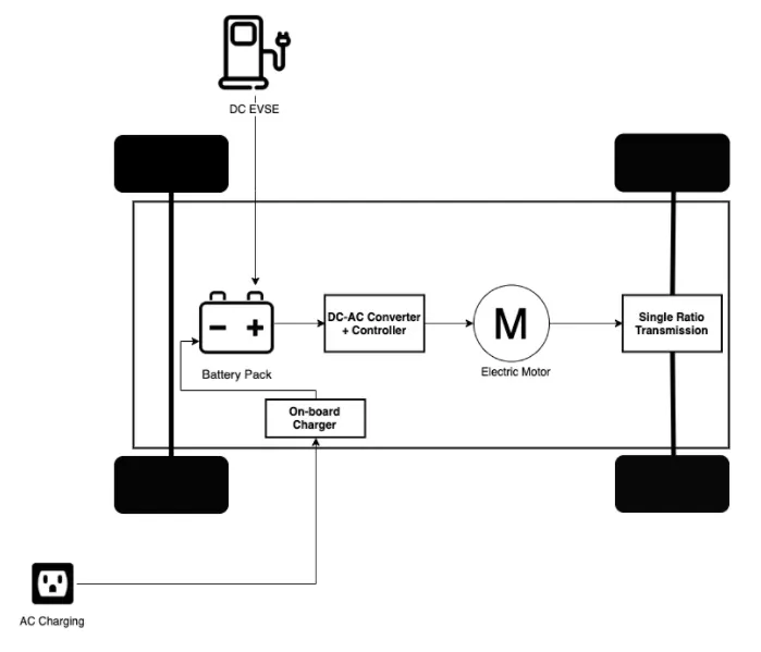
Q7). A. Design an electric powertrain with type of motor, it’s power rating, and energy requirement to fulfill aircraft towing application in Simulink. Estimate the duty cycle range to control the aircraft speed from zero to highest. Make all required assumptions. Prepare a table of assumed parameters. Draw a block diagram of the powertrain.
From the above Q.6, we have obtained the value of the power of towing vehicle to push/pull an aircraft with respect to our given velocity and now we have to find out the energy required for the vehicle.
Energy required for the vehicle:
Energy = Power x t
Where,
t = time taken for towing vehicle
Here, we consider the time taken for towing vehicle as about 20 minutes.
`:.` E = 219.74 x `(1200/3600)`
E = 73.24 kWh
The above data shows how much power is taken at the speed of 20 kmph and how much energy is consumed in 20 minutes of time.
In this case, we have to find out the input power to drive the duty cycle of the towing vehicle. The output power is considered from the study-6 that values are based upon certain assumptions and calculations from the towing vehicle model as Douglas Tugmaster type TBL-280 Mk4 from the website.
The formula for duty cycle is given below,
Duty cycle = Power input/Power output
We know,
Power = Voltage x Current
Here we consider,
Input Voltage supply (Motor Specification) = 400 V
Input Current Value = 620 A
Now substitute the voltage and current value in the power formula to get the input power data,
Power input = 400 x 620 = 248000 W
By converting the unit of power from W to kW we get,
Power input = 248 kW
Therefore we have obtained power input and power output now substitute these values in the duty cycle formula we get,
Duty cycle = Power output/Power input
= 219.74/248
= 0.886
So, The duty cycle for the towing vehicle Douglas Tugmaster type TBL-280 Mk4 is 88.6%. This duty is obtained for our system based upon several assumptions.
Block Diagram of Electric Powertrain:
Q7). B. Also, Design the parameters in an excel sheet.
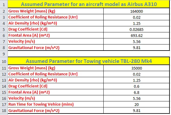
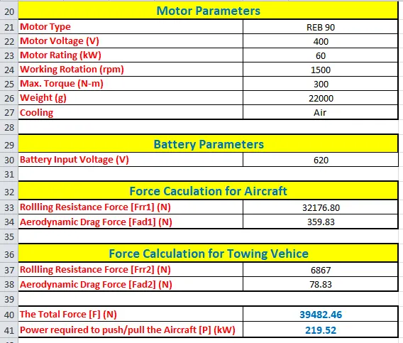
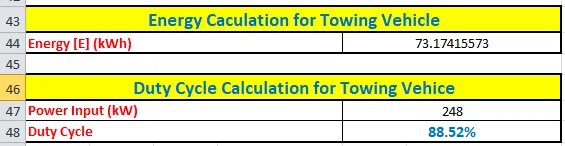
Excel File Link: https://docs.google.com/spreadsheets/d/16gSSocmn1aoUWwtirnC6LITP5oMsxLtL/edit?usp=sharing&ouid=116831111479567673042&rtpof=true&sd=true
Conclusion:
Therefore, all the various studies about the aircraft are analyzed, and calculations to find the force and power required to push/pull an aircraft by a towing vehicle and energy requirement to fulfill aircraft towing application are also determined. The values of the mathematical expression from Q.6 and Q.7 are given below,
Power = 219.74 kW
Energy = 73.24 kWh
Duty Cycle = 88.6%
Reference:
- https://pilotteacher.com/how-much-do-airplanes-weigh-with-20-examples/
- https://www.grc.nasa.gov/www/k-12/airplane/move.html#:~:text=Airspeed%20is%20the%20vector%20difference,speed%20and%20the%20wind%20speed.&text=On%20a%20perfectly%20still%20day,less%20than%20the%20ground%20speed.
- https://en.wikipedia.org/wiki/Pushback
- https://en.wikipedia.org/wiki/Takeoff
- https://webstor.srmist.edu.in/web_assets/srm_mainsite/files/downloads/class17-2012.pdf
- http://www.aviation-history.com/theory/lift.htm
- https://en.wikipedia.org/wiki/Aircraft_tire
- https://www.aviationhunt.com/aircraft-tyre-construction/
- https://www.aviationpros.com/aircraft/article/10388042/understanding-the-basics-of-aircraft-tire-construction-and-maintenance
- https://aerocorner.com/blog/do-airplanes-have-brakes/
- https://monroeaerospace.com/blog/how-do-airplanes-brake-when-landing/
- https://textrongse.txtsv.com/vehicles/tbl-280
- http://tamagawa-as.jp/pdf/gse11_jp.pdf
- https://www.airbus.com/en/who-we-are/our-history/commercial-aircraft-history/previous-generation-aircraft/a310