Project-1: Powertrain for aircraft in runways
OBJECTIVE:
PART A:
- To Search and list out the total weight of various types of aircrafts.
- To find out is there any difference between ground speed and air speed.
- To justify Why is it not recommended to use aircraft engine power to move it on the ground at Airport.
- To find how an aircraft is pushed to runway when its ready to take off.
- To learn about take-off power, Tyre design, rolling resistance, Tyre pressure, brake forces when landing.
PART B:
- To calculate the force and power required to push / pull an aircraft by a towing vehicle, With necessary assumptions.
- To develop the model for the calculated force and power using Simulink.
- To design an electric powertrain with type of motor, it’s power rating, and energy requirement to fulfill aircraft towing application in Simulink. Estimate the duty cycle range to control the aircraft speed from zero to highest. Make all required assumptions. Prepare a table of assumed parameters. Draw a block diagram of powertrain.
- To also, design the parameters in excel sheet.
SOLUTION:
PART - A:
OBJECTIVE - 1:
TO SEARCH AND LIST OUT TOTAL WEIGHT OF VAARIOUS TYPES OF AIRCRAFTS:
- Aircraft Empty Weight (AEW)
- This is sometimes referred to as OEW – Operating Empty Weight and it is the weight of the aircraft with all its equipment on board but no fuel, no passengers or no cargo.
- Think of this like the aircraft has just come out of the factory and is sitting waiting to be fueled up for delivery to the customer.
- Aircraft Maximum Gross Take-off Weight (MGTW)
- This is the maximum permissible weight the aircraft can weigh as it lifts off the ground at take-off. This includes the aircraft’s empty weight, the fuel, the crew, the passengers, and all the cargo.
- This weight limit is set by the manufacturer and is gospel. Many aircraft accidents have been caused by an aircraft being overweight and the pilot/s have not had enough power or maneuverability to prevent the accident.
- Aircraft Useful Load
- This is the weight that a pilot can place in the aircraft. Take the MGTW figure and subtract the AEW and this is the total useful load that can be placed into the aircraft. This is the fuel, crew, passengers, and cargo. The bigger the load, the more useful the aircraft can be to its customers
- Total weight of various aircrafts:
| AIRCRAFT | MAX GROSS TAKEOFF WEIGHT (KG) |
| Antonov An-225 | 640000 |
| Scaled Composites Model 351 Stratolaunch | 589670 |
| Airbus A380-800 | 575000 |
| Boeing 747-8F | 447700 |
| Boeing 747-8 | 443613 |
| Boeing 747-400ER | 412770 |
| Antonov An-124-100M | 405060 |
| Boeing 747-400 | 396900 |
| Lockheed C-5 Galaxy | 381000 |
| Boeing 747-200 | 377840 |
| Boeing 747-300 | 377840 |
| Airbus A340-500 | 371950 |
| Airbus A340-600 | 367400 |
| Boeing 777F | 347800 |
| Boeing 777-300ER | 351800 |
| Boeing 777-200LR | 347450 |
| Boeing 747-100 | 340200 |
| Airbus A350-1000 | 308000 |
| Boeing 777-300 | 299370 |
| Boeing 777-200ER | 297550 |
| Airbus A340-300 | 276700 |
| McDonnell Douglas MD-11 | 273300 |
| Airbus A350-900 | 270000 |
| Ilyushin Il-96M | 270000 |
| McDonnell Douglas DC-10 | 256280 |
| Boeing 787-9 | 254000 |
| Boeing 787-10 | 254000 |
| Airbus A340-200 | 253500 |
| Airbus A330-900 | 251000 |
| Ilyushin IL-96-300 | 250000 |
| Airbus A330-300 | 242000 |
| Airbus A330-200 | 242000 |
| Lockheed L-1011-500 | 231300 |
| Boeing 787-8 | 228000 |
| Lockheed L-1011-200 | 211400 |
| Ilyushin IL-86 | 208000 |
| Boeing 767-400ER | 204000 |
| Airbus A300-600R | 192000 |
| Boeing 767-300ER | 187000 |
| Concorde | 185000 |
| Airbus A300-600 | 163000 |
| Boeing 767-300 | 159000 |
| Airbus A310-300 | 157000 |
| Vickers VC10 | 152000 |
| Boeing 707-320B | 151000 |
| Boeing 707-320C | 151000 |
| Douglas DC-8-61 | 147000 |
| Airbus A310-200 | 142000 |
| Airbus A400M | 141000 |
| Douglas DC-8-32 | 140000 |
| Douglas DC-8-51 | 125000 |
| Boeing 757-300 | 124000 |
| Boeing 707-120B | 117000 |
| Boeing 757-200 | 116000 |
| Boeing 720B | 106000 |
| Boeing 720 | 104000 |
| Tupolev Tu-154M | 104000 |
| Tupolev Tu-204SM | 104000 |
| Convair 880 | 87500 |
| Boeing 737-900 | 85000 |
| Boeing 737-900ER | 85000 |
| Boeing 727-200 Advanced | 84000 |
| Airbus A321-100 | 83000 |
| Boeing 737-800 | 79000 |
| Boeing 727-200 | 78000 |
| McDonnell-Douglas MD-83 | 73000 |
| Boeing 727-100 | 72500 |
| Boeing 727-100C | 72500 |
| McDonnell-Douglas MD-90-30 | 71000 |
| de Havilland Comet 4 | 70700 |
| Boeing 737-700 | 70000 |
| Airbus A320-100 | 68000 |
| Boeing 737-400 | 68000 |
| de Havilland Comet 3 | 68000 |
| Boeing 377 | 67000 |
| Boeing 737-600 | 66000 |
| Airbus A220-300 | 65000 |
| Hawker Siddeley Trident 2E | 65000 |
| Airbus A319 | 64000 |
| Boeing 737-300 | 63000 |
| Boeing 737-500 | 60000 |
| Airbus A220-100 | 59000 |
| Airbus A318 | 59000 |
| Boeing 717-200HGW | 55000 |
| Douglas DC-7 | 55000 |
| de Havilland Comet 2 | 54000 |
| Boeing 717-200BGW | 50000 |
| de Havilland Comet 1 | 50000 |
| Douglas DC-6A | 48600 |
| Douglas DC-6B | 48500 |
| Embraer 190 | 48000 |
| Caravelle III | 46000 |
| Fokker 100 | 46000 |
| Douglas DC-6 | 44000 |
| Avro RJ-85 | 42000 |
| Handley Page Hermes | 39000 |
| Embraer 175 | 37500 |
| Bombardier CRJ900 | 36500 |
| Embraer 170 | 36000 |
| Bombardier CRJ700 | 33000 |
| Douglas DC-4 | 33000 |
| Vickers Viscount 800 | 30400 |
| Bombardier Q400 | 28000 |
| Bombardier CRJ200 | 23000 |
| ATR 72-600 | 22800 |
| Saab 2000 | 22800 |
| Embraer ERJ 145 | 22000 |
| ATR 42-500 | 18600 |
| Saab 340 | 13150 |
| Embraer 120 Brasilia | 11500 |
| BAe Jetstream 41 | 10890 |
| Learjet 75 | 9752 |
| Pilatus PC-24 | 8300 |
| Embraer Phenom 300 | 8150 |
| Beechcraft 1900D | 7765 |
| Cessna Citation CJ4 | 7761 |
| de Havilland Hercules | 7000 |
| Embraer Phenom 100 | 4800 |
| Beechcraft King Air B100 | 5400 |
| Diamond DA50RG | 2000 |
| Beechcraft Bonanza G36 | 1660 |
| Cessna 206H | 1630 |
| Sirrus SR22 | 1630 |
| Cessna 172R | 1100 |
OBJECTIVE - 2:
DIFFERENCE BETWEEN GROUND SPEED AND AIR SPEED:
- True airspeed is simply the speed at which an aircraft is moving relative to the air it is flying in. As such, it’s also the speed at which the air is flowing around the aircraft’s wings.
- Ground speed, on the other hand, is the aircraft’s speed relative to the ground. One thing that should be noted here is that it’s its horizontal rather than vertical speed – an aircraft climbing completely vertically would have a ground speed of zero.
- In other words, while airspeed is what determines whether there is enough airflow around an aircraft to make it fly, ground speed is what determines how fast an aircraft will get to its destination.
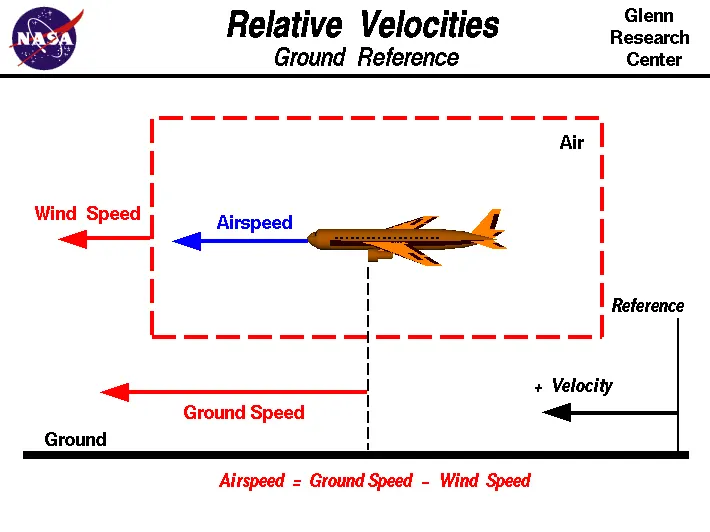
- The relationship between airspeed and ground speed is fairly simple. Ground speed is simply the sum of airspeed and wind speed.
- If the aircraft is flying in the same direction as the wind is blowing, the aircraft experiences tailwind, and its ground speed is higher than its airspeed. On the other hand, if the wind is blowing against the direction the aircraft is traveling in, the aircraft experiences headwind, and its ground speed is lower than its airspeed.
- Wind Speed
- For a reference point picked on the ground, the air moves relative to the reference point at the wind speed. Notice that the wind speed is a vector quantity and has both a magnitude and a direction. Direction is important. A 20 mph wind from the west is different from a 20 mph wind from the east. The wind has components in all three primary directions (north-south, east-west, and up-down). In this figure, we are considering only velocities along the aircraft's flight path. A positive velocity is defined to be in the direction of the aircraft's motion. We are neglecting cross winds, which occur perpendicular to the flight path but parallel to the ground, and updrafts and downdrafts, which occur perpendicular to the ground.
- Ground Speed
- For a reference point picked on the ground, the aircraft moves relative to the reference point at the ground speed. Ground speed is also a vector quantity so a comparison of the ground speed to the wind speed must be done according to rules for vector comparisons.
- Airspeed
- The important quantity in the generation of lift is the relative velocity between the object and the air, which is called the airspeed. Airspeed cannot be directly measured from a ground position, but must be computed from the ground speed and the wind speed. Airspeed is the vector difference between the ground speed and the wind speed.
- Airspeed = Ground Speed - Wind Speed
- On a perfectly still day, the airspeed is equal to the ground speed. But if the wind is blowing in the same direction that the aircraft is moving, the airspeed will be less than the ground speed.
OBJECTIVE - 3:
WHY IS IT NOT RECOMMENDED TO USE ENGINE POWER TO MOVE THE AIRCRAFT ON THE GROUND AT THE AIRPORT:
- Planes move by pulling or pushing themselves through the air, rather than by applying engine power to spin their wheels, and thus have no forward or reverse gears. Like ground vehicles' engines, the aircraft's engines can't run backwards.
- Here is where the pushbacks come in. The vehicles obviously do not have the strength to push the plane. However, all they have to do is lift the plane and overcome the inertia. Watch the video of a lift here.
- Airplanes are pushed back from the gate to prevent reverse thrust from the engines being used. Reverse thrust requires high engine power creating high-speed jet blast. Any debris can damage airport terminals, jet ways & ground vehicles. Pilots also cannot see behind making reversing very hazardous.
- Large airplanes required a lot of force to get moving from a dead stop. There are two ways to get a plane moving:
- Use the engines to provide reverse thrust
- Use a tow vehicle to push the airplane back
- Using the engines to create reverse thrust is accomplished by using deflector scoops on each engine to channel the thrust airflow sideward and slightly forwards. This is mainly used to aid in slowing the aircraft down during landing but can allow the aircraft to reverse, but it has implications.
- Older aircraft that had their engines mounted high up on the rear of the aircraft could use reverse thrust to back out from the gate but with most modern airplanes the engines are mounted under the wing placing them close to the ground.
- When an airplane uses reverse thrust it takes a high-power setting to get the aircraft moving initially. This creates a high-speed wind that can easily damage the airport terminal, jet way, surrounding ground vehicles, baggage, and ground personnel and cause debris to be ingested by the engine – not good!
- For propeller-based aircraft like the Bombardier Dash 8 they can reverse the pitch of the propeller blades forcing the thrust forwards and propelling the airplane backward. Again, this creates high-speed debris and airflow that can cause problems on a busy airport apron.
- By far the most common option is to use a tow vehicle to hook up to that airplane and propel it backward without the airplane’s engines running.
- By doing this it allows for:
- Far greater safety because the tow truck operator has a much better view of the entire area surrounding and under the aircraft
- The vehicle driver is in communication with the pilots to ensure aircraft braking can be applied if needed in an emergency
- With the aid of ground personnel who walk under the wingtips, the tow truck driver can precisely position the aircraft and ensure it does not contact any structure, vehicle, person or aircraft
- It allows the airports ground controllers to get aircraft moved with much greater time constraints thus improving the flow around the apron and gate areas.
OBJECTIVE - 4:
HOW AN AIRCRAFT IS PUSHED TO THE RUNWAY WHEN IT IS READY TO TAKE-OFF:
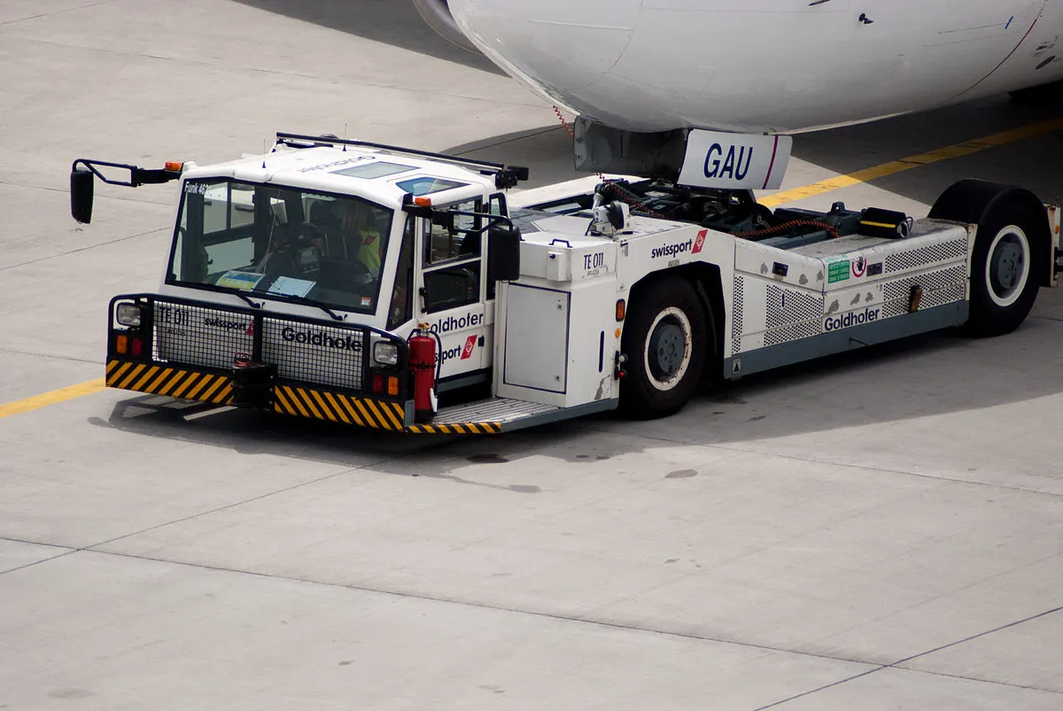
- In aviation, pushback is an airport procedure during which an aircraft is pushed backwards away from its parking position, usually at an airport gate by external power. Pushbacks are carried out by special, low-profile vehicles called pushback tractors or tugs.
- Although many aircraft are capable of moving themselves backwards on the ground using reverse thrust (a procedure referred to as a power back), the resulting jet blast or prop wash would cause increased noise, damage to the terminal building or equipment, and hurt airport staff due to high-speed debris. This debris would also be sucked into the engine, as it is in normal use, and cause excessive wear - a major cause of wear on aircraft engines is during ground use. A pushback is therefore the preferred method when ground-handling aircraft.
- Pushbacks at busy aerodromes are usually subject to ground control clearance to facilitate ground movement on taxiways. Once clearance is obtained, the pilot will communicate with the tractor driver (or a ground handler walking alongside the aircraft in some cases) to start the pushback. To communicate, a headset may be connected near the nose gear.
- Since the pilots cannot see what is behind the aircraft, steering is done by the pushback tractor driver and not by the pilots. Depending on the aircraft type and airline procedure, a bypass pin may be temporarily installed into the nose gear to disconnect it from the aircraft's normal steering mechanism.
- Once the pushback is completed, the towbar is disconnected, and any bypass pin removed. The ground handler will show the bypass pin to the pilots to make it clear that it has been removed. The pushback is then complete, and the aircraft can taxi forward under its own power.
- Large aircraft cannot be moved by hand and must have a tractor or tug. Pushback tractors use a low-profile design to fit under the aircraft nose. For sufficient traction the tractor must be heavy, and most models can have extra ballast added. A typical tractor for large aircraft weighs up to 54 Tonnes (59.5 short tons; 53.1 long tons; 119,000 pounds) and has a drawbar pull of 334 KN (75,000 lbf). Often the driver's cabin can be raised for increased visibility when reversing and lowered to fit under aircraft. There are two types of pushback tractors: conventional and towbar less (TBL).
- Conventional tugs use a tow bar to connect the tug to the nose landing gear of the aircraft. The tow bar is fixed laterally at the nose landing gear, but may move slightly vertically for height adjustment. At the end that attaches to the tug, the tow bar may pivot freely laterally and vertically. In this manner the tow bar acts as a large lever to rotate the nose landing gear. Each aircraft type has a unique tow fitting so the towbar also acts as an adapter between the standard-sized tow pin on the tug and the type-specific fitting on the aircraft's landing gear. The tow bar must be long enough to place the tug far away enough to avoid hitting the aircraft and to provide sufficient leverage to facilitate turns. On heavy tow bars for large aircraft the towbar rides on its own wheels when not connected to an aircraft. The wheels are attached to a hydraulic jacking mechanism which can lift the towbar to the correct height to mate to both the airplane and the tug, and once this is accomplished the same mechanism is used in reverse to raise the tow bar wheels from the ground during the pushback process. The tow bar can be connected at the front or the rear of the tractor, depending on whether the aircraft will be pushed or pulled. The towbar has a shear pin which prevents the aircraft from being mishandled by the tug; when overstressed the shear pin will snap, disconnecting the bar from the nose gear to prevent damage to the aircraft and tug.
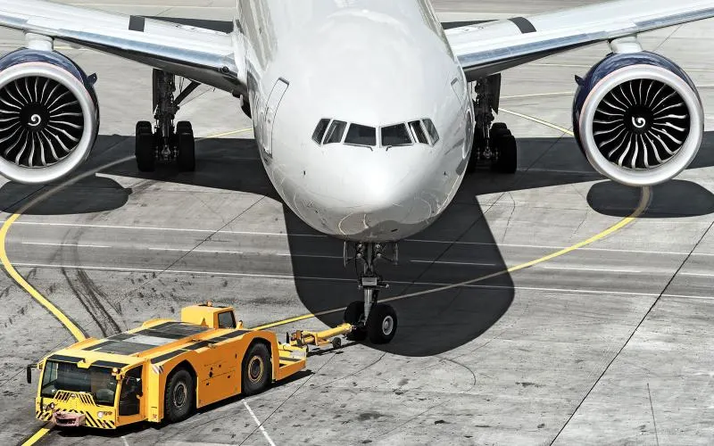
- Towbarless (TBL) tractors do not use a towbar; they scoop up the nose landing gear and lift it off the ground. This avoids the time penalty of connecting/disconnecting a towbar, and entirely removes the cost/complexity of maintaining towbars on the ramp. The tug itself does not need to be particularly massive - the aircraft's nose wheel weight provides the necessary downward force. Lastly, a TBL tug is much shorter (compared to a tug + towbar system) and has one only a single pivot points instead of one at either end of the towbar, so it has much simpler and precise control of the aircraft. This is very useful in general aviation settings with a wider variety of aircraft in more confined spaces than their airline counterparts.
- Manufacturers of electric TBL tugs offer models capable of moving any aircraft from the smallest single-engine type to narrow-body airliners, military cargo and airline-sized business jets. Just as specialized towbars are required for a wide range of aircraft, many TBL tugs use adapters which enable the movement of many unique aircraft. The majority of aircraft do not require adapters and can be moved without any special adjustments to the tug. This is in contrast to conventional tugs which often use so-called "universal" towbars which must be adjustable to suit many aircraft types. Electric TBL tugs are gaining popularity among general aviation operators and FBOs as an alternative to gas or diesel-powered conventional tugs. Being electric rather than internal combustion-powered, electric tugs are low-emission which is a major advantage for environmentally-conscious operators; this also enables the tug to be safely operated inside a closed hangar.
Robotic tractor
- The Lahav Division of Israel Aerospace Industries has developed a semi-robotic towbarless tractor it calls Taxibot that can tow an aircraft from the terminal gate to the take-off point (taxi-out phase) and return it to the gate after landing (taxi-in phase). The Taxibot eliminates the use of airplane engines during taxi-in and until immediately prior to take-off during taxi-out potentially saving airlines billions of dollars in fuel that is used. The Taxibot is controlled by the pilot from the cockpit using the regular pilot controls.
Other Applications
- While the vehicle is referred to as a pushback tug, it is also used to tow aircraft in areas where taxiing the aircraft is not practical or is unsafe, such as moving aircraft in and out of maintenance hangars, or moving aircraft that are not under their own power.
- Some airlines, notably Virgin Atlantic, advocated towing aircraft to the holding point of the runway to save fuel and reduce environmental impact, however, the practice was discontinued after landing gear maintenance costs increased due to the stresses originating during the towing process.
- Some fuel must still be burned to operate the auxiliary power unit to provide electrical and pneumatic power to run lighting, environmental and communications systems, unless the tug itself provides these sources of power, which some do. This method also places a larger workload on ground crews and equipment, especially if the aircraft and tow tractor end up having to wait in a long line of aircraft.
OBJECTIVE - 5:
TAKE-OFF POWER:
- Take-off is the phase of flight in which an aerospace vehicle leaves the ground and becomes airborne. For aircraft traveling vertically, this is known as lift-off.
- For aircraft that take off horizontally, this usually involves starting with a transition from moving along the ground on a runway. For ballons, helicopters and some specialized fixed-wing aircraft (VTOL aircraft such as the Harrier and the Bell Boeing V22 Osprey), no runway is needed.
- For light aircraft, usually full power is used during takeoff. Large transport category (airliner) aircraft may use a reduced power for takeoff, where less than full power is applied in order to prolong engine life, reduce maintenance costs and reduce noise emissions. In some emergency cases, the power used can then be increased to increase the aircraft's performance. Before takeoff, the engines, particularly piston engines, are routinely run up at high power to check for engine-related problems. The aircraft is permitted to accelerate to rotation speed (often referred to as Vr). The term rotation is used because the aircraft pivots around the axis of its main landing gear while still on the ground, usually because of gentle manipulation of the flight controls to make or facilitate this change in aircraft attitude (once proper air displacement occurs under / over the wings, an aircraft will lift off on its own; controls are to ease that in).
- The nose is raised to a nominal 5–15° nose up pitch attitude to increase lift from the wings and effect liftoff. For most aircraft, attempting a takeoff without a pitch-up would require cruise speeds while still on the runway.
- Fixed-wing aircraft designed for high-speed operation (such as commercial jet aircraft) have difficulty generating enough lift at the low speeds encountered during takeoff. These are therefore fitted with high-lift devices, often including slats and usually flaps, which increase the camber and often area of the wing, making it more effective at low speed, thus creating more lift. These are deployed from the wing before takeoff, and retracted during the climb. They can also be deployed at other times, such as before landing.
- The speeds needed for takeoff are relative to the motion of the air (indicated airspeed). A headwind will reduce the ground speed needed for takeoff, as there is a greater flow of air over the wings. Typical takeoff air speeds for jetliners are in the range of 240–285 Km/h (130–154 KN; 149–177 mph). Light aircraft, such as a Cessna 150, take off at around 100 Km/h (54 KN; 62 mph). Ultralights have even lower takeoff speeds. For a given aircraft, the takeoff speed is usually dependent on the aircraft weight; the heavier the weight, the greater the speed needed. Some aircraft are specifically designed for short take-off and landing (STOL), which they achieve by becoming airborne at very low speeds.
- The takeoff speed required varies with aircraft weight and aircraft configuration (flap or slat position, as applicable), and is provided to the flight crew as indicated airspeed.
- Operations with transport category aircraft employ the concept of the takeoff V-Speeds: V1, VR and V2. These speeds are determined not only by the above factors affecting takeoff performance, but also by the length and slope of the runway and any peculiar conditions, such as obstacles off the end of the runway. Below V1, in case of critical failures, the takeoff should be aborted; above V1 the pilot continues the takeoff and returns for landing. After the co-pilot calls V1, they will call VR or "rotate," marking speed at which to rotate the aircraft. The VR for transport category aircraft is calculated such as to allow the aircraft to reach the regulatory screen height at V2 with one engine failed. Then, V2 (the safe takeoff speed) is called. This speed must be maintained after an engine failure to meet performance targets for rate of climb and angle of climb.
- In a single-engine or light twin-engine aircraft, the pilot calculates the length of runway required to take off and clear any obstacles, to ensure sufficient runway to use for takeoff. A safety margin can be added to provide the option to stop on the runway in case of a rejected take-off. In most such aircraft, any engine failure results in a rejected takeoff as a matter of course, since even overrunning the end of the runway is preferable to lifting off with insufficient power to maintain flight.
- If an obstacle needs to be cleared, the pilot climbs at the speed for maximum climb angle (Vx), which results in the greatest altitude gain per unit of horizontal distance travelled. If no obstacle needs to be cleared, or after an obstacle is cleared, the pilot can accelerate to the best rate of climb speed (Vy), where the aircraft will gain the most altitude in the least amount of time. Generally speaking, Vx is a lower speed than Vy, and requires a higher pitch attitude to achieve.
- Assisted takeoff is any system for helping aircraft into the air (as opposed to strictly under its own power). The reason it might be needed is due to the aircraft's weight exceeding the normal maximum take-off weight, insufficient power, or the available runway length may be insufficient, or a hot and high airfield, or a combination of all four factors. Assisted takeoff is also required for gliders, which do not have an engine and so are unable to take off by themselves. Hence assisted takeoff is required.
Take off Performance
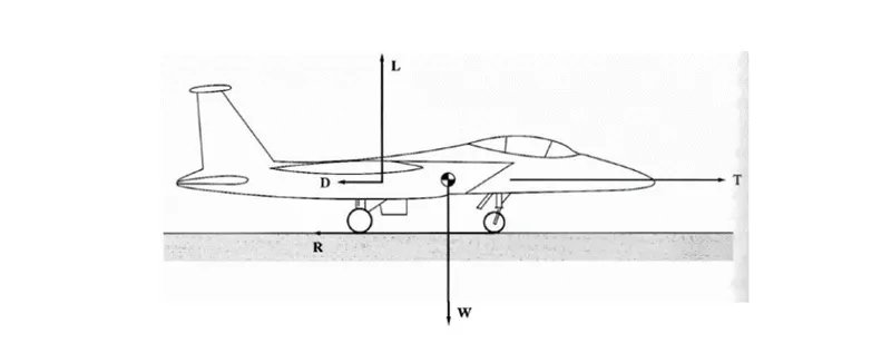
- An airplane is motionless at the end of a runway. This is denoted by location O. The pilot releases the brakes and pushes the throttle to maximum takeoff power, and the airplane accelerates down the runway. At some distance from its starting point, the airplane lifts into the air. The distance the airplane cover along the runway before it lifts into the air is called the ground roll (sg). The total takeoff distance also includes the extra distance covered over the ground after the airplane is airborne but before it clears an obstacle of 50 ft for military aircraft and 35 ft for commercial aircraft. This is denoted by sa. The sum of sg and sa is the total takeoff distance.
- As the airplane accelerates from zero velocity, at some point it will reach the stalling velocity VStall • The airplane continues to accelerate until it reaches the minimum control speed on the ground, Vmcg. This is the minimum velocity at which enough aerodynamic force can be generated on the vertical fin with rudder deflection while the airplane is still rolling along the ground to produce a yawing moment sufficient to counteract that produced when there is an engine failure for a multiengine aircraft. • If the airplane were in the air (without the landing gear in contact with the ground), the minimum speed required for yaw control in case of engine failure is slightly greater than Vmcg This velocity is called the minimum control speed in the air, Vmca • The airplane continues to accelerate until it reaches the decision speed, V1. This is the speed at which the pilot can successfully continue takeoff even though an engine failure (in a multiengine aircraft) would occur at this point. If an engine fails before V1 is achieved, the takeoff must be stopped. If an engine fail after V1 is reached, the takeoff has to be completed.
- The airplane continues to accelerate until the takeoff rotational speed, VR is achieved. At this velocity, the pilot initiates by elevator deflection a rotation of the airplane in order to increase the angle of attack and to overcome the weight. Attention should be paid not to stall. • the angle of attack necessary to overcome the weight may not be achievable because the tail may drag the ground. If the rotation of the airplane is limited by ground clearance for the tail, the airplane must continue to accelerate while rolling along the ground after rotation is achieved. This speed is called the minimum unstick speed, denoted by Vus. • For increased safety, the angle of attack after rotation is slightly less than the maximum allowable by tail clearance, and the airplane continues to accelerate to a slightly higher velocity, called the lift off speed, denoted by VLO. This is the point at which the airplane actually lifts off the ground. The total distance covered along the ground to this point is the ground roll sg. • Generally VLO=1.1 Vstall
TYRE DESIGN:
- When it comes to safety, tires are one of the most important components of aircraft. They help to absorb the shock of landing and provide cushioning. It also provides the necessary traction for braking and stopping of an aircraft.
- An aircraft tire is designed to withstand extremely heavy loads while landing, take off, taxing, and parking. The number of wheels required for aircraft increases with the weight of the aircraft, as the weight of the airplane needs to be distributed more evenly.
- A Boeing 737NG & 737MAX uses 6 wheels, Boeing 787 uses 10 wheels, Boeing 777 uses 14 wheels and Airbus A380 uses 22 wheels. Aircraft tires work under extreme conditions, carrying up to 340 tons and accelerating at over 250 km/hour at takeoff, in addition to enduring varied environmental stress when in flight and taxiing.
AIRCRAFT TIRES AND TUBES:
- Aircraft tires may be tube-type or tubeless. They support the weight of the aircraft while it is on the ground and provide the necessary traction for braking and stopping. The tires also help absorb the shock of landing and cushion the roughness of takeoff, rollout, and taxi operations. Aircraft tires must be carefully maintained to perform as required. They accept a variety of static and dynamic stresses and must do so dependably in a wide range of operating conditions.
TIRE CLASSIFICATION
- Aircraft tires are classified in various ways including by: type, ply rating, whether they are tube-type or tubeless, and whether they are bias ply tires or radials. Identifying a tire by its dimensions is also used. Each of these classifications is discussed as follows.
TYPES:
- A common classification of aircraft tires is by type as classified by the United States Tire and Rim Association. While there are nine types of tires, only Types I, III, VII, and VIII, also known as a Three-Part Nomenclature tire, are still in production.
- Type I tires are manufactured, but their design is no longer active. They are used on fixed gear aircraft and are designated only by their nominal overall diameter in inches. These are smooth profile tires that are obsolete for use in the modern aviation fleet. They may be found on older aircraft.
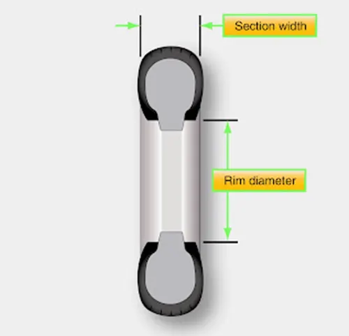
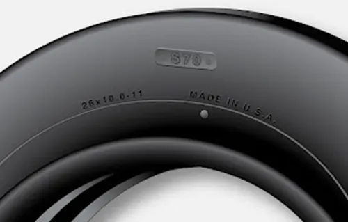
- Type III tires are common general aviation tires. They are typically used on light aircraft with landing speeds of 160 miles per hour (mph) or less. Type III tires are relatively low-pressure tires that have small rim diameters when compared to the overall width of the tire. They are designed to cushion and provide flotation from a relatively large footprint. Type III tires are designated with a two number system. The first number is the nominal section width of the tire, and the second number is the diameter of the rim the tire is designed to mount upon.
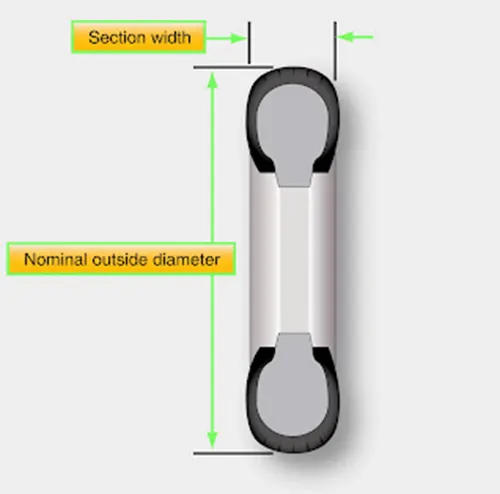
- Type VII tires are high performance tires found on jet aircraft. They are inflated to high-pressure and have exceptional high load carrying capability. The section width of Type VII tires is typically narrower than Type III tires. Identification of Type VII aircraft tires involves a two-number system. An X is used between the two numbers. The first number designates the nominal overall diameter of the tire. The second number designates the section width.
-
Type VIII aircraft tires are also known as three-part nomenclature tires. [Figure 3] They are inflated to very high-pressure and are used on high-performance jet aircraft. The typical Type VIII tire has relatively low profile and is capable of operating at very high speeds and very high loads. It is the most modern design of all tire types. The three-part nomenclature is a combination of Type III and Type VII nomenclature where the overall tire diameter, section width, and rim diameter are used to identify the tire. The X and “–” symbols are used in the same respective positions in the designator.
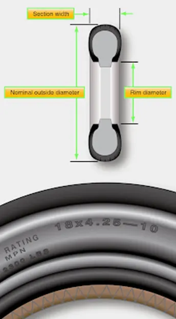
- When three-part nomenclature is used on a Type VIII tire, dimensions may be represented in inches or in millimeters. Bias tires follow the designation nomenclature and radial tires replace the “–” with the letter R. For example, 30 X 8.8 R 15 designates a Type VIII radial aircraft tire with a 30-inch tire diameter, an 8.8-inch section width to be mounted on a 15-inch wheel rim.
- A few special designators may also be found for aircraft tires. When a B appears before the identifier, the tire has a wheel rim to section width ratio of 60 to 70 percent with a bead taper of 15 degrees. When an H appears before the identifier, the tire has a 60 to 70 percent wheel rim to section width ratio but a bead taper of only 5 degrees.
PLY RATING
- Tire plies are reinforcing layers of fabric encased in rubber that are laid into the tire to provide strength. In early tires, the number of plies used was directly related to the load the tire could carry. Nowadays, refinements to tire construction techniques and the use of modern materials to build up aircraft tires makes the exact number of plies somewhat irrelevant.
- when determining the strength of a tire. However, a ply rating is used to convey the relative strength of an aircraft tire. A tire with a high ply rating is a tire with high strength able to carry heavy loads regardless of the actual number of plies used in its construction.
TUBE-TYPE OR TUBELESS
- As stated, aircraft tires can be tube-type or tubeless. This is often used as a means of tire classification. Tires that are made to be used without a tube inserted inside have an inner liner specifically designed to hold air. Tube-type tires do not contain this inner liner since the tube holds the air from leaking out of the tire. Tires that are meant to be used without a tube have the word tubeless on the sidewall. If this designation is absent, the tire requires a tube. Consult the aircraft manufacturer’s maintenance information for any allowable tire damage and the use of a tube in a tubeless tire.
BIAS PLY OR RADIAL
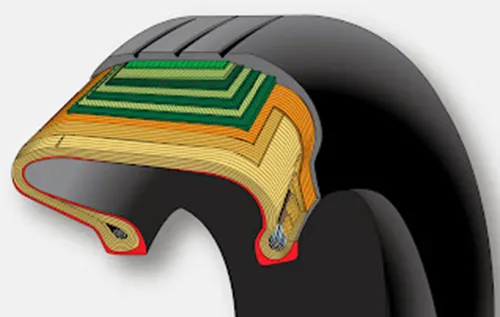
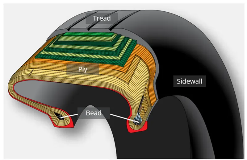
- Another means of classifying an aircraft tire is by the direction of the plies used in construction of the tire, either bias or radial. Traditional aircraft tires are bias ply tires. The plies are wrapped to form the tire and give it strength. The angle of the plies in relation to the direction of rotation of the tire varies between 30° and 60°. In this manner, the plies have the bias of the fabric from which they are constructed facing the direction of rotation and across the tire. Hence, they are called bias tires. The result is flexibility as the sidewall can flex with the fabric plies laid on the bias.
TIRE CONSTRUCTION
- An aircraft tire is constructed for the purpose it serves. Unlike an automobile or truck tire, it does not have to carry a load for a long period of continuous operation. However, an aircraft tire must absorb the high impact loads of landing and be able to operate at high speeds even if only for a short time. The deflection built into an aircraft tire is more than twice that of an automobile tire. This enables it to handle the forces during landings without being damaged. Only tires designed for an aircraft as specified by the manufacturer should be used.
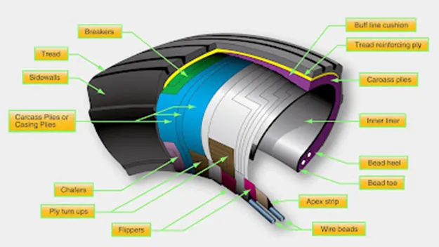
- It is useful to the understanding of tire construction to identify the various components of a tire and the functions contributed to the overall characteristics of a tire. Refer to Figure 6 for tire nomenclature used in this discussion.
BEAD
- The tire bead is an important part of an aircraft tire. It anchors the tire carcass and provides a dimensioned, firm mounting surface for the tire on the wheel rim. Tire beads are strong. They are typically made from high-strength carbon steel wire bundles encased in rubber. One, two, or three bead bundles may be found on each side of the tire depending on its size and the load it is designed to handle. Radial tires have a single bead bundle on each side of the tire. The bead transfers the impact loads and deflection forces to the wheel rim. The bead toe is closest to the tire centerline and the bead heel fit against the flange of the wheel rim.
- An apex strip is additional rubber formed around the bead to give a contour for anchoring the ply turn-ups. Layers of fabric and rubber called flippers are placed around the beads to insulate the carcass from the beads and improve tire durability. Chafers are also used in this area. Chafer strips made of fabric or rubber are laid over the outer carcass plies after the plies are wrapped around the beads. The chafers protect the carcass from damage during mounting and demounting of the tire. They also help reduce the effects of wear and chafing between the wheel rim and the tire bead especially during dynamic operations.
CARCASS PILES
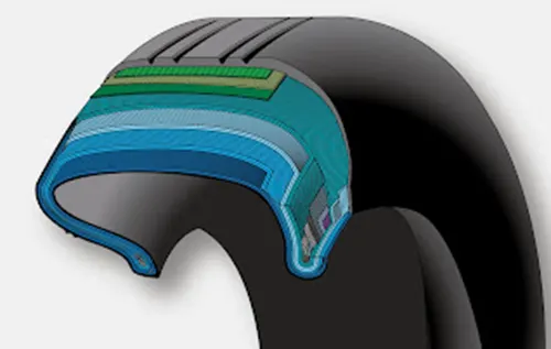
- Carcass plies, or casing plies as they are sometimes called, are used to form the tire. Each ply consists of fabric, usually nylon, sandwiched between two layers of rubber. The plies are applied in layers to give the tire strength and form the carcass body of the tire. The ends of each ply are anchored by wrapping them around the bead on both sides of the tire to form the ply turn-ups. As mentioned, the angle of the fiber in the ply is manipulated to create a bias tire or radial tire as desired. Typically, radial tires require fewer plies than bias tires.
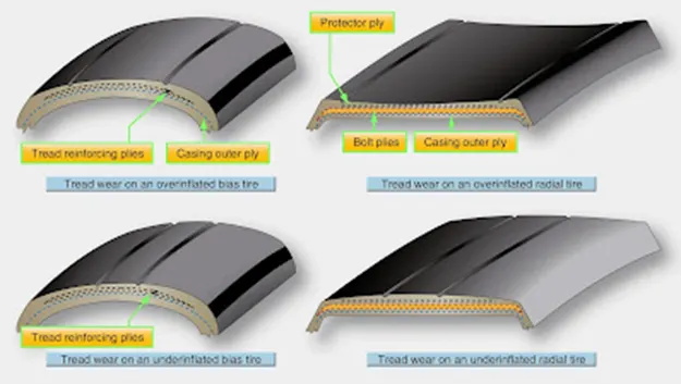
- Once the plies are in place, bias tires and radial tires each have their own type of protective layers on top of the plies but under the tread of the running surface of the tire. On bias tires, these single or multiple layers of nylon and rubbers are called tread reinforcing plies. On radial tires, an undertread and a protector ply do the same job. These additional plies stabilize and strengthen the crown area of the tire. They reduce tread distortion under load and increase stability of the tire at high speeds. The reinforcing plies and protector plies also help resist puncture and cutting while protecting the carcass body of the tire.
TREAD
- The tread is the crown area of the tire designed to come in contact with the ground. It is a rubber compound formulated to resist wear, abrasion, cutting, and cracking. It also is made to resist heat build-up. Most modern aircraft tire tread is formed with circumferential grooves that create tire ribs. The grooves provide cooling and help channel water from under the tire in wet conditions to increase adhesion to the ground surface. Tires designed for aircraft frequently operated from unpaved surfaces may have some type of cross-tread pattern. Older aircraft without brakes or brakes designed only to aid in taxi may not have any grooves in the tread. An all-weather tread may be found on some aircraft tires. This tread has typical circumferential ribs in the center of the tire with a diamond patterned cross tread at the edge of the tire.
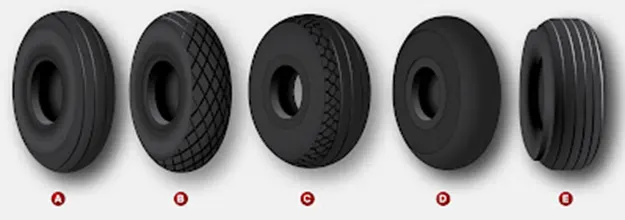
- The tread is designed to stabilize the aircraft on the operating surface and wears with use. Many aircraft tires are designed with protective undertread layers as described above. Extra tread reinforcement is sometimes accomplished with breakers. These are layers of nylon cord fabric under the tread that strengthen the tread while protecting the carcass plies. Tires with reinforced tread are often designed to be re-treaded and used again once the tread has worn beyond limits. Consult the tire manufacturer’s data for acceptable tread wear and re-tread capability for a particular tire.
SIDEWALL
- The sidewall of an aircraft tire is a layer of rubber designed to protect the carcass plies. It may contain compounds designed to resist the negative effects of ozone on the tire. It also is the area where information about the tire is contained. The tire sidewall imparts little strength to the cord body. Its main function is protection.
- The inner sidewall of a tire is covered by the tire inner liner. A tube-type tire has a thin rubber liner adhered to the inner surface to prevent the tube from chafing on the carcass plies. Tubeless tires are lined with a thicker, less permeable rubber. This replaces the tube and contains the nitrogen or inflation air within the tire and keeps from seeping through the carcass plies.
- The inner liner does not contain 100 percent of the inflation gas. Small amounts of nitrogen or air seep through the liner into the carcass plies. This seepage is released through vent holes in the lower outer sidewall of the tires. These are typically marked with a green or white dot of paint and must be kept unobstructed. Gas trapped in the plies could expand with temperature changes and cause separation of the plies, thus weakening the tire leading to tire failure. Tube-type tires also have seepage holes in the sidewall to allow air trapped between the tube and the tire to escape.
CHINE
- Some tire sidewalls are mounded to form a chine. A chine is a special built-in deflector used on nose wheels of certain aircraft, usually those with fuselage mounted engines. The chine diverts runway water to the side and away from the intake of the engines. [Figure 7-E] Tires with a chine on both sidewalls are produced for aircraft with a single nose wheel.
TIRE INSPECTION ON THE AIRCRAFT
- Tire condition is inspected while mounted on the aircraft on a regular basis. Inflation pressure, tread wear and condition, and sidewall condition are continuously monitored to ensure proper tire performance.
INFLATION
- To perform as designed, an aircraft tire must be properly inflated. The aircraft manufacturer’s maintenance data must be used to ascertain the correct inflation pressure for a tire on a particular aircraft. Do not inflate to a pressure displayed on the sidewall of the tire or by how the tire looks. Tire pressure is checked while under load and is measured with the weight of the aircraft on the wheels. Loaded versus unloaded pressure readings can vary as much as 4 percent. Tire pressure measured with the aircraft on jacks or when the tire is not installed is lower due to the larger volume of the inflation gas space inside of the tire. On a tire designed to be inflated to 160 psi, this can result in a 6.4 psi error. A calibrated pressure gauge should always be used to measure inflation pressure. Digital and dial-type pressure gauges are more consistently accurate and preferred.
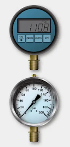
- Aircraft tires disperse the energy from landing, rollout, taxi, and takeoff in the form of heat. As the tire flexes, heat builds and is transferred to the atmosphere, as well as to the wheel rim through the tire bead. Heat from braking also heats the tire externally. A limited amount of heat is able to be handled by any tire beyond which structural damage occurs.
- An improperly inflated aircraft tire can sustain internal damage that is not readily visible and that can lead to tire failure. Tire failure upon landing is always dangerous. An aircraft tire is designed to flex and absorb the shock of landing. Temperature rises as a result. However, an underinflated tire may flex beyond design limits of the tire. This causes excessive heat build-up that weakens the carcass construction. To ensure tire temperature is maintained within limits, tire pressure must be checked and maintained within the proper range on a daily basis or before each flight if the aircraft is only flown periodically.
- Tire pressure should be measured at ambient temperature. Fluctuations of ambient temperature greatly affect tire pressure and complicate maintenance of pressure within the allowable range for safe operation. Tire pressure typically changes 1 percent for every 5 °F of temperature change. When aircraft are flown from one environment to another, ambient temperature differences can be vast. Maintenance personnel must ensure that tire pressure is adjusted accordingly. For example, an aircraft with the correct tire pressure departing Phoenix, Arizona where the ambient temperature is 100 °F arrives in Vail, Colorado where the temperature is 50 °F. The 50° difference in ambient temperature results in a 10 percent reduction in tire pressure. Therefore the aircraft could land with underinflated tires that may be damaged due to over-temperature from flexing beyond design limits as described above. An increase in tire pressure before takeoff in Phoenix, Arizona prevents this problem as long as the tires are not inflated beyond the allowable limit provided in the maintenance data.
- When checking tire pressure, allow 3 hours to elapse after a typical landing to ensure the tire has cooled to ambient temperature. The correct tire pressure for each ambient temperature is typically provided by the manufacturer on a table or graph.
- In addition to overheating, under inflated aircraft tires wear unevenly, which leads to premature tire replacement. They may also creep or slip on the wheel rim when under stress or when the brakes are applied. Severely under inflated tires can pinch the sidewall between the rim and the runway causing sidewall and rim damage. Damage to the bead and lower sidewall area are also likely. This type of abuse like any over flexing damages the integrity of the tire and it must be replaced. In dual-wheel setups, a severely underinflated tire affects both tires and both should be replaced.
- Over inflation of aircraft tires is another undesirable condition. While carcass damage due to overheating does not result, adherence to the landing surface is reduced. Over a long period of time, over inflation leads to premature tread wear. Therefore, over inflation reduces the number of cycles in service before the tire must be replaced. It makes the tire more susceptible to bruises, cutting, shock damage, and blowout.
TREAD CONDITION
- Condition of an aircraft tire tread is able to be determined while the tire is inflated and mounted on the aircraft. The following is a discussion of some of the tread conditions and damage that the technician may encounter while inspecting tires.
TREAD DEPTH AND WEAR PATTERN
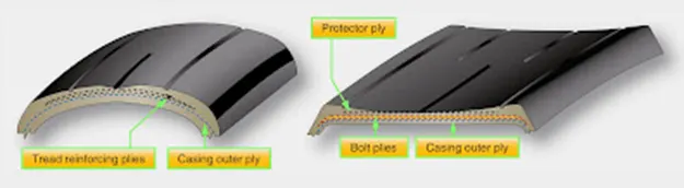
- Evenly worn tread is a sign of proper tire maintenance. Uneven tread wear has a cause that should be investigated and corrected. Follow all manufacturer instructions specific to the aircraft when determining the extent and serviceability of a worn tire. In the absence of this information, remove any tire that has been worn to the bottom of a tread groove along more than 1ś8 of the circumference of the tire. If either the protector ply on a radial tire or the reinforcing ply on a bias tire is exposed for more than 1ś8 of the tire circumference, the tire should also be removed. A properly maintained evenly worn tire usually reaches its wear limits at the centerline of the tire.
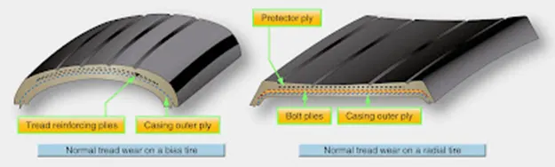
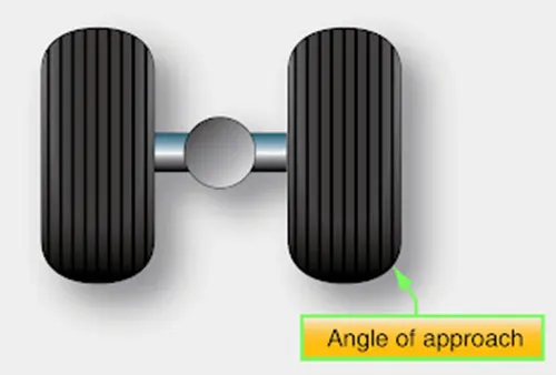
- Asymmetrical tread wear may be caused by the wheels being out of alignment. Follow the manufacturer’s instructions while checking caster, camber, tow-in, and tow-out to correct this situation. Occasionally, asymmetrical tire wear is a result of landing gear geometry that cannot, or is not, required to be corrected. It may also be caused by regular taxiing on a single engine or high speed cornering while taxiing. It is acceptable to remove the tire from the wheel rim, turn it around, and remount it to even up tread wear if the tire passes all other criterion of inspection for serviceability.
- Removal of a tire before it is worn beyond limits to be eligible for retreading is cost effective and good maintenance practice. Considerable traction is lost when tire tread is severely worn and must also be considered when inspecting a tire for condition. Consult airframe manufacturer and tire manufacturer specifications for wear and retread limitations.
TREAD DAMAGE
- In addition to tread wear, an aircraft tire should be inspected for damage. Cuts, bruises, bulges, imbedded foreign objects, chipping, and other damage must be within limits to continue the tire in service. Some acceptable methods of dealing with this type of damage are described below. All damage, suspected damage, and areas with leaks should be marked with chalk, a wax marker, paint stick, or other device before the tire is deflated or removed. Often, it is impossible to relocate these areas once the tire is deflated. Tires removed for retread should be marked in damaged areas to enable closer inspection of the extent of the damage before the new tread is installed.

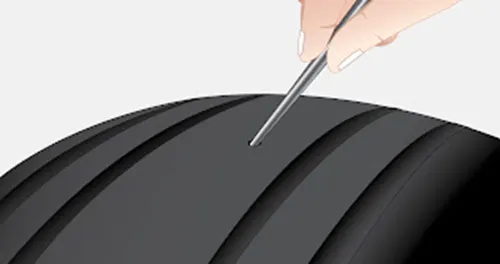
- Foreign objects imbedded in a tire’s tread are of concern and should be removed when not imbedded beyond the tread. Objects of questionable depth should only be removed after the tire has been deflated. A blunt awl or appropriately sized screwdriver can be used to pry the object from the tread. Care must be exercised to not enlarge the damaged area with the removal tool. [Figure 14] Once removed, assess the remaining damage to determine if the tire is serviceable. A round hole caused by a foreign object is acceptable only if it is 3/8-inch or less in diameter. Embedded objects that penetrate or expose the casing cord body of a bias ply tire or the tread belt layer of a radial tire cause the tire to become unairworthy and it must be removed from service.
- Cuts and tread undercutting can also render a tire unairworthy. A cut that extends across a tread rib is cause for tire removal. These can sometimes lead to a section of the rib to peel off the tire. Consult the aircraft maintenance manual, airline operations manual, or other technical documents applicable to the aircraft tire in question.
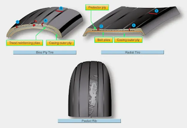
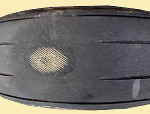
- A flat spot on a tire is the result of the tire skidding on the runway surface while not rotating. This typically occurs when the brakes lock on while the aircraft is moving. If the flat spot damage does not expose the reinforcing ply of a bias tire or the protector ply of a radial tire, it may remain in service. However, if the flat spot causes vibration, the tire must be removed. Landing with a brake applied can often cause a severe flat spot that exposes the tire under tread. It can also cause a blowout. The tire must be replaced in either case.
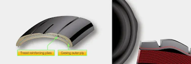
- A bulge or separation of the tread from the tire carcass is cause for immediate removal and replacement of the tire. Mark the area before deflation as it could easily become undetectable without air in the tire.
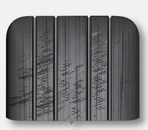
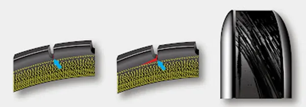
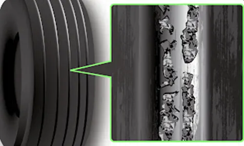
- Operation on a grooved runway can cause an aircraft tire tread to develop shallow chevron shaped cuts. These cuts are allowed for continued service, unless chunks or cuts into the fabric of the tire result. Deep chevrons that cause a chunk of the tread to be removed should not expose more than 1 square inch of the reinforcing or protector ply. Consult the applicable inspection parameters to determine the allowable extent of chevron cutting.
- Tread chipping and chunking sometimes occurs at the edge of the tread rib. Small amounts of rubber lost in this way are permissible. Exposure of more than 1 square inch of the reinforcing or protector ply is cause for removal of the tire.
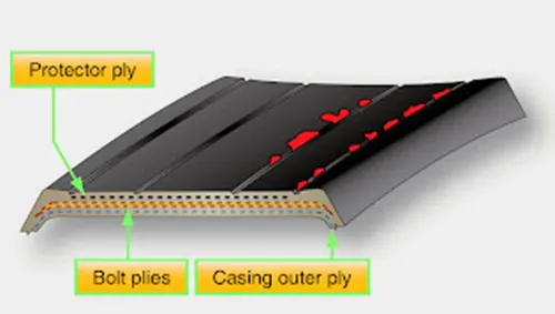
- Cracking in a tread groove of an aircraft tire is generally not acceptable if more than ¼-inch of the reinforcing or protector ply is exposed. Groove cracks can lead to undercutting of the tread, which eventually can cause the entire tread to be thrown from the tire.
- Oil, hydraulic fluid, solvents, and other hydrocarbon substances contaminate tire rubber, soften it, and make it spongy. A contaminated tire must be removed from service. If any volatile fluids come in contact with the tire, it is best to wash the tire or area of the tire with denatured alcohol followed by soap and water. Protect tires from contact with potentially harmful fluids by covering tires during maintenance in the landing gear area.
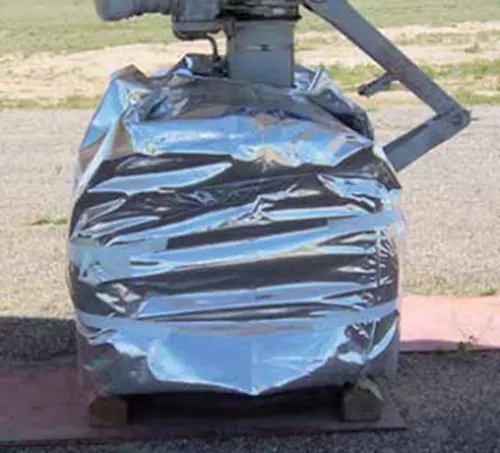
- Tires are also subject to degradation from ozone and weather. Tires on aircraft parked outside for long periods of times can be covered for protection from the elements
SIDEWALL CONDITION
- The primary function of the sidewall of an aircraft tire is protection of the tire carcass. If the sidewall cords are exposed due to a cut, gouge, snag, or other injury, the tire must be replaced. Mark the area of concern before removal of the tire. Damage to the sidewall that does not reach the cords is typically acceptable for service. Circumferential cracks or slits in the sidewall are unacceptable. A bulge in a tire sidewall indicates possible delamination of the sidewall carcass plies. The tire must immediately be removed from service.
- Weather and ozone can cause cracking and checking of the sidewall. If this extends to the sidewall cords, the tire must be removed from service. Otherwise, sidewall checking as show in Figure 22 does not affect the performance of the tire and it may remain in service.
TIRE REMOVAL
- Removal of any tire and wheel assembly should be accomplished following all aircraft manufacturer’s instructions for the procedure. Safety procedures are designed for the protection of the technician and the maintenance of aircraft parts in serviceable condition. Follow all safety procedures to prevent personal injury and damage to aircraft parts and assemblies.
- An aircraft tire and wheel assembly, especially a high-pressure assembly that has been damaged or overheated, should be treated as though it may explode. Never approach such a tire while its temperature is still elevated above ambient temperature. Once cooled, approach a damage tire and wheel assembly from an oblique angle advancing toward the shoulder of the tire.
-
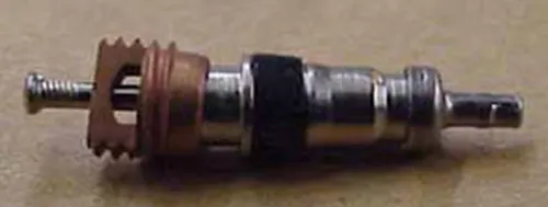
Deflate all unserviceable and damaged tires before removal from the aircraft. Use a valve core/deflation tool to deflate the tire. Stand to the side—away from the projectile path of the valve core. A dislodged valve core propelled by internal tire pressure can cause serious human injury. When completely deflated, remove the valve core. [Figure 24] A tire and wheel assembly in airworthy condition may be removed to access other components for maintenance without deflating the tire. This is common practice, such as when accessing the brake when the wheel assembly is immediately reinstalled. For tracking purposes, ensure damaged areas of a tire are marked before deflation. Record all known information about an unserviceable tire and attach it to the tire for use by the retread repair station.
- Once removed from the aircraft, a tire must be separated from the wheel rim upon which is mounted. Proper equipment and technique should be followed to avoid damage to the tire and wheel. The wheel manufacturer’s maintenance information is the primary source for dismounting guidelines.
- The bead area of the tire sits firmly against the rim shoulder and must be broken free. Always use proper bead breaking equipment for this purpose. Never pry a tire from a wheel rim as damage to the wheel is inevitable. The wheel tie bolts must remain installed and fully tightened when the bead is broken from the rim to prevent damage to the wheel half mating surfaces.
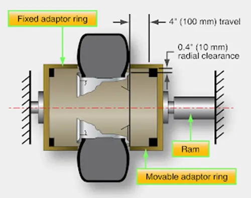
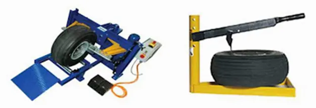
- When the bead breaking press contact surface is applied to the tire, it should be as close to the wheel as possible without touching it during the entire application of pressure. Tires and rims of different sizes require contact pads suitable for the tire. Hand presses and hydraulic presses are available. Apply the pressure and hold it to allow the bead to move on the rim. Gradually progress around the rim until the tire bead is broken free. Ring-type bead breakers apply pressure around the circumference of the entire sidewall so rotation is not required. [Figure 25] Once the bead is broken free, the wheel halves may be disassembled. [Figure 26] Radial tires have only one bead bundle on each side of the tire. The sidewall is more flexible in this area than a bias ply tire. The proper tooling should be used, and pressure should be applied slowly to avoid heavy distortion of the sidewall. Lubrication may be applied and allowed to soak into the tire-wheel interface. Only soapy tire solutions should be used. Never apply a hydrocarbon-based lubricant to an aircraft tire as this contaminates the rubber compound used to construct the tire. Beads on tube-type and tubeless tires are broken free in a similar manner.
TIRE INSPECTION OF THE AIRCRAFT
- Once a tire has been removed from the wheel rim, it should be inspected for condition. It may be possible to retread the tire at an approved repair station and return it to service. A sequential inspection procedure helps ensure no parts of the tire are overlooked. Mark and record the extent of all damage. Tires must only be repaired by those with the experience and equipment to do so. Most tire repairs are accomplished at a certified tire repair facility.
- When inspecting a tire removed from the aircraft, pay special attention to the bead area since it must provide an air tight seal to the wheel rim and transfer forces from the tire to the rim. Inspect the bead area closely as it is where the heat is concentrated during tire operation. Surface damage to the chafer is acceptable and can be repaired when the tire is retreaded. Other damage in the bead area is usually cause for rejection. Damage to the turn-ups, ply separation at the bead, or a kinked bead are examples of bead area damage that warrant the tire be discarded. The bead area of the tire may sustain damage or have an altered appearance or texture on a tire that has been overheated. Consult a certified tire repair station or re-tread facility when in doubt about the condition observed. The wheel rim must also be inspected for damage. An effective seal without slippage, especially on tubeless tires, is dependent on the condition and integrity of the wheel in the bead seat area.
- Overheating of a tire weakens it even though the damage might not be obvious. Any time a tire is involved in an aborted takeoff, severe braking, or the thermal plug in the wheel has melted to deflate the tire before explosion, the tire must be removed. On a dual installation, both tires must be removed. Even if only one tire shows obvious damage or deflates, the loads experienced by the mate are excessive. Internal damage such as ply separation, is likely. The history of having been through an overheat event is all that is required for the tire to be discarded.
- Damaged or suspected damaged areas of the tire should be re-inspected while the tire is off the aircraft. Cuts can be probed to check for depth and extent of damage below the tread. In general, damage that does not exceed 40 percent of the tire plies can be repaired when the tire is retreaded. Small punctures with a diameter on the tire inner surface of less than 1/8-inch and a diameter on the outer surface of less than 1/4-inch can also be repaired and retreaded. A bulge caused by ply separation is reason to discard a tire. However, a bulge caused by tread separation from the tire carcass may be repairable during retread. Exposed sidewall cord or sidewall cord damage is unacceptable and the tire cannot be repaired or retreaded. Consult the tire manufacturer or certified retreader for clarification on damage to a tire.
TIRE REPAIR AND RETREADING
- The technician should follow airframe and tire manufacturer instructions to determine if a tire is repairable. Many example guidelines have also been given in this section. Nearly all tire repairs must be made at a certified tire repair facility equipped to perform the approved repair. Bead damage, ply separation, and sidewall cord exposure all require that the tire be scrapped. Inner liner condition on tubeless tires is also critical. Replacing the tube in a tube-type tire is performed by the technician as are mounting and balancing all types of aircraft tires.
- Aircraft tires are very expensive. They are also extremely durable. The effective cost of a tire over its life can be reduced by having the tread replaced while the carcass is still sound and injuries are within repairable limits. The technician inspects a tire to pre-qualify it for retread so that the cost of shipping it to the retread repair facility is not incurred if there is no chance to retread the tire. The tire retreader inspects and tests every tire to a level beyond the capability of the hangar or line technician. Shearography, an optical nondestructive testing method that provides detailed information about the internal integrity of the tire, is used by tire retread repair facilities to ensure a tire carcass is suitable for continued service.
- Tires that are retreaded are marked as such. They are not compromised in strength and give the performance of a new tire. No limits are established for the number of times a tire can be retreaded. This is based on the structural integrity of the tire carcass. A well maintained main gear tire may be able to be retreaded a handful of times before fatigue renders the carcass un-airworthy. Some nose tires can be retread nearly a dozen times.
TIRE STORAGE
- An aircraft tire can be damaged if stored improperly. A tire should always be stored vertically so that it is resting on its treaded surface. Horizontal stacking of tires is not recommended. Storage of tires on a tire rack with a minimum 3–4-inch flat resting surface for the tread is ideal and avoids tire distortion.
- If horizontal stacking of tires is necessary, it should only be done for a short time. The weight of the upper tires on the lower tires cause distortion possibly making it difficult for the bead to seat when mounting tubeless tires. A bulging tread also stresses rib grooves and opens the rubber to ozone attack in this area. [Figure 27] Never stack aircraft tires horizontally for more than 6 months. Stack no higher than four tires if the tire is less than 40-inches in diameter and no higher than three tires if greater than 40-inches in diameter. The environment in which an aircraft tire is stored is critical. The ideal location in which to store an aircraft tire is cool, dry, and dark, free from air currents and dirt.
- An aircraft tire contains natural rubber compounds that are prone to degradation from chemicals and sunlight. Ozone (O3) and oxygen (O2) cause degradation of tire compounds. Tires should be stored away from strong air currents that continually present a supply of one or both of these gases. Fluorescent lights, mercury vapor lights, electric motors, battery chargers, electric welding equipment, electric generators, and similar shop equipment produce ozone and should not be operated near aircraft tires. Mounted inflated tires can be stored with up to 25 percent less pressure than operating pressure to reduce vulnerability from ozone attacks. Sodium vapor lighting is acceptable. Storage of an aircraft tire in the dark is preferred to minimize degradation from ultraviolet (UV) light. If this is not possible, wrap the tire in dark polyethylene or paper to form an ozone barrier and to minimize exposure to UV light.
- Common hydrocarbon chemicals, such as fuels, oils, and solvents, should not contact a tire. Avoid rolling tires through spills on the hangar or shop floor and be sure to clean any tire immediately if contaminated. Dry the tire and store all tires in a dry place away from any moisture, which has a deteriorating effect on the rubber compounds. Moisture with foreign elements may further damage the rubber and fabric of a tire. Dirty areas must be avoided.
- Tires are made to operate in a wide range of temperatures. However, storage should be at cool temperatures to minimize degradation. A general range for safe aircraft tire storage is between 32 °F and 104 °F. Temperatures below this are acceptable but higher temperatures must be avoided.
AIRCRAFT TUBES
- Many aircraft tires accept a tube inside to contain the inflation air. Tube-type tires are handled and stored in similar fashion as tubeless tires. A number of issues concerning the tubes themselves must be addressed.
TUBE CONSTRUCTION AND SELECTION
- Aircraft tire tubes are made of a natural rubber compound. They contain the inflation air with minimal leakage. Unreinforced and special reinforced heavy duty tubes are available. The heavy duty tubes have nylon reinforcing fabric layered into the rubber to provide strength to resist chafing and to protect against heat such as during braking. Tubes come in a wide range of sizes. Only the tube specified for the applicable tire size must be used. Tubes that are too small stress the tube construction.
TUBE STORAGE AND INSPECTION
- An aircraft tire tube should be kept in the original carton until put into service to avoid deterioration through exposure to environmental elements. If the original carton is not available, the tube can be wrapped in several layers of paper to protect it. Alternately, for short time periods only, a tube may be stored in the correct size tire it is made for while inflated just enough to round out the tube. Application of talc to the inside of the tire and outside of the tube prevents sticking. Remove the tube and inspect it and the tire before permanently mounting the assembly. Regardless of storage method, always store aircraft tubes in a cool, dry, dark place away from ozone producing equipment and moving air.
- When handling and storing aircraft tire tubes, creases are to be avoided. These weaken the rubber and eventually cause tube failure. Creases and wrinkles also tend to be chafe points for the tube when mounted inside the tire. Never hang a tube over a nail or peg for storage.
- An aircraft tube must be inspected for leaks and damage that may eventually cause a leak or failure. To check for leaks, remove the tube from the tire. Inflate the tube just enough to have it take shape but not stretch. Immerse a small tube in a container of water and look for the source of air bubbles. A large tube may require that water be applied over the tube. Again, look for the source of bubbles. The valve core should also be wetted to inspect it for leaks.
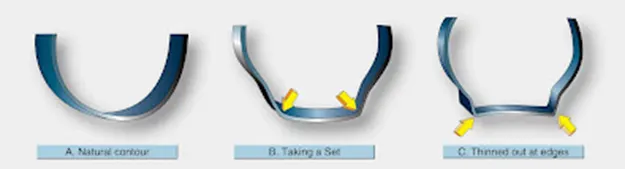
- There is no mandatory age limit for an aircraft tire tube. It should be elastic without cracks or creases in order to be consider serviceable. The valve area is prone to damage and should be inspected thoroughly. Bend the valve to ensure there are no cracks at the base where it is bonded to the tire or in the area where it passes through the hole in the wheel rim. Inspect the valve core to ensure it is tight and that it does not leak. If an area of a tube experiences chafing to the point where the rubber is thinned, the tube should be discarded. The inside diameter of the tube should be inspected to ensure it has not been worn by contact with the toe of the tire bead. Tubes that have taken an unnatural set should be discarded.
TIRE INSPECTION
- It is important to inspect the inside of a tube-type tire before installing a tube for service. Any protrusions or rough areas should be cause for concern, as these tend to abrade the tube and may cause early failure. Follow the tire, tube, and aircraft manufacturer’s inspection criterion when inspecting aircraft tires and tubes.
TIRE MOUNTING
- A licensed technician is often called upon to mount an aircraft tire onto the wheel rim in preparation for service. In the case of a tube-type tire, the tube must also be mounted. The following section presents general procedures for these operations using tube-type and tubeless tires. Be sure to have the proper equipment and training to perform the work according to manufacturer’s instructions.
TUBELESS TIRES
- Aircraft tire and wheel assemblies are subject to enormous stress while in service. Proper mounting ensures tires perform to the limits of their design. Consult and follow all manufacturer’s service information including bolt torques, lubrication and balancing requirements, and inflation procedures.
- As mentioned, a wheel assembly that is to have a tire mounted upon it must be thoroughly inspected to ensure it is serviceable. Pay close attention to the bead seat area, which should be smooth and free from defects. The wheel half mating surface should be in good condition. The O-ring should be lubricated and in good condition to ensure it seals the wheel for the entire life of the tire. Follow the manufacturer’s instructions when inspecting wheels and the tips provided earlier in this chapter.
- A final inspection of the tire to be mounted should be made. Most important is to check that the tire is specified for the aircraft application. It should say tubeless on the sidewall. The part number, size, ply rating, speed rating, and technical standard order (TSO) number should also be on the sidewall and be approved for the aircraft installation. Visually check the tire for damage from shipping and handling. There should be no permanent deformation of the tire. It should pass all inspections for cuts and other damage discussed in the previous sections of this chapter. Clean the tire bead area with a clean shop towel and soap and water or denatured alcohol. Inspect the inside of the tire for condition. There should be no debris inside the tire.
- Tire beads are sometimes lubricated when mounted on aluminum wheels. Follow the manufacturer’s instructions and use only the non-hydrocarbon lubricant specified. Never lubricate any tire bead with grease. Do not use lubricants with magnesium alloy wheels. Most radial tires are mounted without lubricant. The airframe manufacturer may specify lubrication for a radial tire in a few cases.
- When the wheel halves and tires are ready to be mounted, thought must be given to tire orientation and the balance marks on the wheel halves and tire. Typically, the tire serial number is mounted to the outboard side of the assembly. The marks indicating the light portion of each wheel half should be opposite each other. The mark indicating the heavy spot of the wheel assembly should be mounted aligned with the light spot on the tire, which is indicated by a red mark. If the wheel lacks a mark indicating the heavy spot, align the red spot on the tire (the light point) with the valve fitting location on the wheel. A properly balanced tire and wheel assembly improves the overall performance of the tire. It promotes smooth operation free from vibration, which results in uniform tread wear and extended tire life.
- When assembling the wheel halves, follow manufacturer’s instructions for tie bolt tightening sequences and torque specification. Anti-seize lubricants and wet-torque values are common on wheel assemblies. Use a calibrated hand torque wrench. Never use an impact wrench on an aircraft tire assembly.
- For the initial inflation of an aircraft tire and wheel assembly, the tire must be placed in a tire inflation safety cage and treated as though it may explode due to wheel or tire failure. The inflation hose should be attached to the tire valve stem, and inflation pressure should be regulated from a safe distance away. A minimum of 30 feet is recommended. Air or nitrogen should be introduced gradually as specified. Dry nitrogen keeps the introduction of water into the tire to a minimum, which helps prevent corrosion. Observe the tire seating progress on the wheel rim while it inflates. Depressurize the tire before approaching it to investigate any observed issue.
- Aircraft tires are typically inflated to their full specified operating pressure. Then, they are allowed to remain with no load applied for 12-hours. During this time, the tire stretches and tire pressure decreases. A 5-10 percent reduction is normal. Upon bringing the tire up to full pressure again, less than 5 percent loss per day of pressure is allowable. More should be investigated.
TUBE-TYPE TIRES
- Wheel and tire inspection should precede the mounting of any tire, including tube-type tires. The tube to be installed must also pass inspection and must be the correct size for the tire and tire must be specified for the aircraft. Tire talc is commonly used when installing tube-type tires to ensure easy mounting and free movement between the tube and tire as they inflate. The technician should lightly talc the inside of the tire and the outside of the tube. Some tubes come from the factory with a light talc coating over the outside of the tube. Inflate the tube so that it just takes shape with minimal pressure. Install the tube inside the tire. Tubes are typically produced with a mark at the heavy spot of the tube. In the absence of this balance mark, it is assumed that the valve is located at the heaviest part of the tube. For proper balance, align the heavy part of the tube with the red mark on the tire (the light spot on the tire).
- Once wheel balance is marked and the tube balance mark and the tire balance mark are all positioned correctly, install the outboard wheel half so the valve stem of the tube passes through the valve stem opening. [Figure 30] Mate the inboard wheel half to it, being careful not to pinch the tube between the wheel rims. Install the tie bolts, tighten, and torque as specified. Inflate the assembly in a tire inflation cage. The inflation procedure for a tube-type tire differs slightly from that of a tubeless tire. The assembly is slowly brought up to full operating pressure. Then, it is completely deflated. Re‑inflate the tire/tube assembly a second time to the specified operating pressure and allow it to remain with no load for 12-hours. This allows any wrinkles in the tube to smooth out, helps prevent the tube from being trapped under a bead, and generally evens how the tube lays within the tire to avoid any stretched areas and thinning of the tube. The holding time allows air trapped between the tube and the tire to work its way out of the assembly, typically through the tire sidewall or around the valves stem.
TIRE BALANCING
- Once an aircraft tire is mounted, inflated, and accepted for service, it can be balanced to improve performance. Vibration is the main result of an imbalanced tire and wheel assembly. Nose wheels tend to create the greatest disturbance in the cabin when imbalanced.
- Static balance is all that is required for most aircraft tires and wheels. A balance stand typically accepts the assembly on cones. The wheel is free to rotate. The heavy side moves to the bottom. [Figure 31] Temporary weights are added to eliminate the wheel from rotating and dropping the heavy side down. Once balanced, permanent weights are installed. Many aircraft wheels have provisions for securing the permanent weight to the wheel. Weights with adhesive designed to be glued to the wheel rim are also in use. Occasionally, a weight in the form of a patch glued to the inside of the tire is required. Follow all manufacturer’s instructions and use only the weights specified for the wheel assembly.
- Some aviation facilities offer dynamic balancing of aircraft tire and wheel assemblies. While this is rarely specified by manufacturers, a well-balanced tire and wheel assembly helps provide shimmy free operation and reduces wear on brake and landing gear components, such as torque links.
ROLLING RESISTANCE:
- Rolling resistance is the combination of forces that work against the forward motion of your vehicle. The weight of the vehicle, gravity and inertia, the amount of friction between the tires and the road surface, and air drag all play a part. When you coast in your car or on a bike, rolling resistance is what slows you down. The more rolling resistance, the more power it takes to propel a vehicle. Between 3 and 11 percent of the gas used in passenger vehicles goes to overcoming this force, so reducing it means saving on gas.
- Since tires contribute to between 15 and 25 percent of a vehicle’s overall rolling resistance — depending on how fast you’re going, vehicle type and road surface — they are a significant factor in gas economy.
- When a loaded wheel and tire is compelled to roll in a given direction, the tire carcass at the ground interface will be deflected due to a combination of the vertical load and the forward rolling effect on the tire carcass (Fig. 8.10). The vertical load tends to flatten the tire's circular profile at ground level, whereas the forward rolling movement of the wheel will compress and spread the leading contact edge and wall in the region of the tread. At the same time, the trailing edge will tend to reduce its contact pressure and expand as it is progressively freed from the ground reaction. The consequences of the continuous distortion and recovery of the tire carcass at ground level means that energy is being used in rolling the tire over the ground and it is not all returned as strain energy as the tire takes up its original shape. (Note that this has nothing to do with a tractive force being applied to the wheel to propel it forward.) Unfortunately, when the carcass is stressed, the strain produced is a function of the stress. On releasing the stress, because the tire material is not perfectly elastic, the strain lags behind so that the strain for a given value of stress is greater when the stress is decreasing than when it is increasing. Therefore, on removing the stress completely, a residual strain remains. This is known as hysteresis and it is the primary cause of the rolling resistance of the tire.
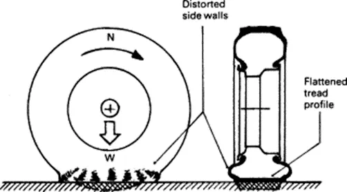
- The secondary causes of rolling resistance are air circulation inside the tire, fan effect of the rotating tire by the air on the outside and the friction between the tire and road caused by tread slippage. A typical analysis of tire rolling resistance losses at high speed can be taken as 90–95% due to internal hysteresis, 2–10% due to friction between the tread and ground, and 1.5–3.5% due to air resistance.
- Rolling resistance is influenced by a number of factors as follows:
- cross-ply tires have higher rolling resistance than radial ply
- the number of carcass plies and tread thickness increase the rolling resistance due to increased hysteresis,
- natural rubber tires tend to have lower rolling resistance than those made from synthetic rubber,
- hard smooth dry surfaces have lower rolling resistances than rough or worn-out surfaces,
- the inflation pressure decreases the rolling resistance on hard surfaces,
- higher driving speed increases the rolling resistance due to the increase in work being done in deforming the tire over a given time
- increasing the wheel and tire diameter reduces the rolling resistance only slightly on hard surfaces but it has a pronounced effect on soft ground,
- Increasing the tractive effort also raises the rolling resistance due to the increased deformation of the tire carcass and the extra work needed to be done.
- Rolling resistance is the energy that is lost when the tire is rolling. The main reason for the loss of energy is the constant deformation of the tire.
- Each bicycle tire should, of course, roll as easily as possible. In contrast to a car a cyclist has only (very limited) physical power which he wants to apply as efficiently as possible.
- In addition to the rolling resistance, there are also other resistances that must be overcome when riding a bicycle:
- The air resistance rises in a squared ratio with increased speed. At a speed of approx. 20 km/h on level ground, air resistance has already become the main resistance force.
- Acceleration energy is also expended. For instance, the weight of the wheels is of great importance when this mass has to be brought up to rotation.
- When riding uphill, the main resistance force to be overcome is the gradient resistance (grade resistance).
- In addition to these, there are other friction resistances in the chain and in other rotating parts. Yet in a well-serviced bicycle, these represent a very minor part of the total resistance.
- Tire pressure, tire diameter, tire width, tire construction, tire tread and other factors all have an effect on rolling resistance.
- On a completely smooth surface the following applies: The higher the inflation pressure, the inferior the tire deformation and thus rolling resistance.
- Off road it is exactly the reverse: The lower the inflation pressure, the lower the rolling resistance. This applies equally on hard gravel roads and soft forest tracks. Explanation: A tire with low inflation pressure can adapt better to a rugged surface. It sinks into the ground less and the whole rotational mass is held back much less by the uneven surface.
- Tires with a smaller diameter have a higher rolling resistance with the same inflation pressure, because tire deformation is proportionally greater. The tire is flattened more and is “less round”.
- Wider tires roll better than narrower tires. This statement generally invokes skepticism, nevertheless, with tires at the same pressure a narrower tire deflects more and so deforms more.
- Obviously, tire construction also has an effect on rolling resistance. By using less material, less material can be deformed. And the more flexible the material is, such as the rubber compound, the less energy is lost through deformation.
- Generally, smooth treads roll better than coarse treads. Tall lugs and wide gaps usually have a detrimental effect on rolling resistance.
- The rolling resistance can be expressed by the generic equation
Fr = µ*W (1)
where,
Fr = rolling resistance or rolling friction (N, lbf)
µ = rolling resistance coefficient - dimensionless (coefficient of rolling friction - CRF)
W = m*g
= normal force - or weight - of the body (N)
m = mass of body (kg)
g = acceleration due to gravity (9.81 m/s2)
Note that the rolling resistance coefficient - µ - is influenced by different variables like wheel design, rolling surface, wheel dimensions and more.
The rolling resistance can alternatively be expressed as
Fr = µ l W / r (2)
Where,
µ l = rolling resistance coefficient - dimension length (coefficient of rolling friction) (mm, in)
r = radius of wheel (mm)
TIRE PRESSURE:
- An aircraft tire or tire is designed to withstand extremely heavy loads for short durations. The number of tires required for aircraft increases with the weight of the aircraft, as the weight of the airplane needs to be distributed more evenly. Aircraft tire tread patterns are designed to facilitate stability in high crosswind conditions, to channel water away to prevent hydroplaning, and for braking effect.
- Aircraft tires also include fusible plugs (which are assembled on the inside of the wheels), designed to melt at a certain temperature. Tires often overheat if maximum braking is applied during an aborted takeoff or an emergency landing. The fuses provide a safer failure mode that prevents tire explosions by deflating in a controlled manner, thus minimizing damage to aircraft and objects in the surrounding environment.
- Each of the twelve Boeing 777-300ER main tires is inflated to 220 psi (15 bar; 1,500 kPa), weighs 120 kg (260 lb), has a diameter of 134 cm (53 in) and is changed every 300 cycles while the brakes are changed every 2000 cycles. Each tire is worth about $5,000. Aircraft tires generally operate at high pressures, up to 200 psi (14 bar; 1,400 KPa) for airliners, and even higher for business jets. The main landing gear on the Concorde was typically inflated to 232 psi (16.0 bar), whilst its tail bumper gear tires were as high as 294 psi (20.3 bar). The high pressure and weight load on the Concorde tires were a significant factor in the loss of Air France Flight 4590.
- Tests of airliner aircraft tires have shown that they are able to sustain pressures of maximum 800 psi (55 bar; 5,500 kPa) before bursting. During the tests the tires have to be filled with water, to prevent the test room being blown apart by the energy that would be released by a gas when the tire bursts.
- Aircraft tires are usually inflated with nitrogen to minimize expansion and contraction from extreme changes in ambient temperature and pressure experienced during flight. Dry nitrogen expands at the same rate as other dry atmospheric gases (normal air is about 80% nitrogen), but common compressed air sources may contain moisture, which increases the expansion rate with temperature.
- The requirement that an inert gas, such as nitrogen, be used instead of air for inflation of tires on certain transport category airplanes was prompted by at least three cases in which the oxygen in air-filled tires had combined with volatile gases given off by a severely overheated tire and exploded upon reaching auto-ignition temperature use of an inert gas for tire inflation eliminates the possibility of tire explosion.
- Of all the things that operators can do to improve the life of the aviation tire, maintaining good pressure maintenance is right at the top of every list. This article briefly explains why pressure maintenance is so important. For more information check out our useful guide!
- No other tire has to deal with such high load and extreme speed as an airplane tire. So, they need a bit more care than the tires on your car or motorcycle.
- Think of the role of the tire as holding the air at a pressure that is able to support the load of the airplane. (Nitrogen is normally used in commercial operations instead of air.)
- Like all thing's aviation, the tire is one part of an assembly which can only work as intended when the parts are used as defined by the airframe and component manufacturers.
- Under-inflating the tire or allowing the tire to operate when it is under-inflated will prevent the parts working together as intended.
- And it will be the tire that will take the strain. It will deflect more and it will wear more. Harsh operating environments will only make it worse.
- Some of the wear will be visible – on the tread and some of the wear will be invisible – inside the structure of the aviation tire.
- Visible Wear
- Under-inflation will increase the footprint of the aviation tire as it rolls on the ground and will increase the build-up of heat. Heat is no friend to tires on airplanes and the tread will wear out more quickly than it should.
- On multi-tire landing gear, the under-inflated tire will force the other, maybe correctly inflated tires, to take a little bit more of the strain. This will wear those other tires a little more.
- Invisible Wear
- As extra heat caused by under-inflation builds up in the airplane tire the internal components of the tire might start to separate from each other. A catastrophic failure might result. Component separation in the casing of the tire will prevent retreading and will increase operating costs. All for a bit of pressure maintenance!
- 24 Hour Pressure Checks
- A carefully thought-out pressure maintenance routine will increase the life of the tire and will reduce the number of wheel changes required.
- As all tires can allow a small pressure decrease during normal operations (due to the intense nature of their service life) airplane operators should check tire pressure every 24 hours.
- Because putting the right pressure in the tires will always take pressure off the airplane operation.
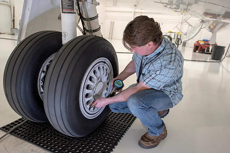
BRAKE FORCES:
- Airplanes rely on a braking system to safely land on runways. At cruising altitude, most commercial airplanes fly at a speed of roughly 500 to 600 mph. When landing, however, they must reduce their speed. A typical 747, for instance, has a landing speed of about 160 to 170 mph. And upon touching the runway, airplanes must quickly brake until they come to a complete stop.
- Wing Spoilers
- Many airplanes use wing spoilers to assist with braking when landing. Not to be confused with ailerons, spoilers are extendable flaps on the ends of an airplane’s wings. Pilots can raise the spoilers to decelerate the airplane as it approaches the runway. And even while on the runway, pilots will typically leave the wing spoilers raised. Raised wing spoilers create drag, which essentially slows down the airplane so that it’s able to brake more quickly.
- Disc Brakes
- In addition to wing spoilers, airplanes use disc brakes. Airplane disc brakes are similar to the braking system in automobiles. They consist of a pair of calipers that, when engaged, squeeze pads against the rotors of an airplane’s landing gear.
- Disc brakes are designed to remain static at all times. In other words, they don’t rotate with the wheels of an airplane’s landing gear. As the wheels turn, the disc brakes will remain static and stationary. They are a vital component of an airplane’s braking system because they are designed to apply pressure to the airplane’s wheels. Disc brakes will squeeze the wheels, thereby slowing down the speed at which they spin. In turn, this reduces the speed of the airplane so that it can come to a complete stop on the runway.
- Reverse Thrust
- Finally, many jet airplanes use reverse thrust to assist with braking during landings. Reverse thrust is a feature in jet engine airplanes that, as the name suggests, involves the reversal of the engines’ thrust. When flying, the thrust is projected out the rear of an airplane’s engines. When landing, however, pilots may use the reverse thrust feature. Reverse thrust changes the direction of the engines’ thrust. Rather than projecting out the rear, the thrust will be projected out the front. This reversal of thrust provides deceleration that allows airplanes to slow down more quickly when landing.
- Aircraft brakes stop a moving aircraft by converting its kinetic energy to heat energy by means of friction between rotating and stationary discs located in brake assemblies in the wheels.
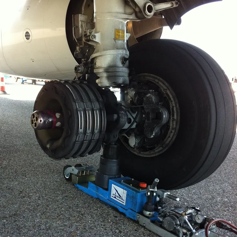
- Brakes provide this critical stopping function during landings to enable airplanes to stop within the length of the runway. They also stop aircraft during rejected takeoff events, in which an attempted takeoff is canceled as the airplane is rolling down the runway before it lifts off from the ground due to engine failure, tire blowout, other system failure or direction from air traffic control.
- Aircraftbrakes also prevent motion of the aircraft when it is parked, limit its speed during taxiing and can even help steer the aircraft on the ground by applying different levels of braking force to the left- and right-side brakes.
- Aircraft brakes work in conjunction with other brake mechanisms such as thrust reversers, air brakes and spoilers. Thrust reversers are surfaces that are deployed into the path of the jet blast from the engines to redirect propulsive thrust in a direction that opposes the motion of the aircraft. Air brakes and spoilers are flight control surfaces that create additional aerodynamic drag when deployed into the path of air flowing around the aircraft.
- The most common type of brake used on aircraft is the disc brake. Disc brakes function by exploiting friction between rotating and stationary discs inside the brake.
- Upon receiving a command signal to brake — from the pilot depressing a foot pedal or from the autobrake system — actuators in the brake move a piston to squeeze the discs together, generating a frictional force that slows the rotation of the wheel. The friction between the discs generates heat as the aircraft’s kinetic energy is converted to heat energy. In this function, the brakes act as a heat sink, absorbing tremendous amounts of heat as the aircraft sheds kinetic energy. During RTO stops, the temperature of carbon disc brakes can exceed 1,800° C.
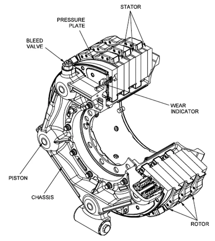
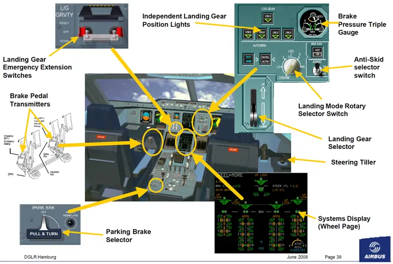
PART - B:
OBJECTIVE - 1:
TO CALCULATE FORCE AND POWER REQUIRED TO PUSH/PULL AN AIRCRAFT BY A TOWING VEHICLE:
ASSUMPTIONS:
- FOR TOWING TRUCK:
- Friction Coefficient = 0.006
- Mass of the vehicle = 25,000 Kg
- Drag coefficient = 0.608
- Frontal Area = 120 m^2
- Velocity of the vehicle = 3 m/sec
- Wheel radius = 0.6096 m
- Gear Ratio = 10
- FOR AIRCRAFT:
- Friction Coefficient = 0.004
- Mass of the vehicle = 3,51,800 Kg
- Drag coefficient = 0.026
- Frontal Area = 6500 m^2
- Velocity of the vehicle = 3 m/sec
- Total Tractive Force = Rolling Resistance Force + Aerodynamic Drag Force + Hill Climbing Force + Acceleration Force
- For calculation of force in this case the Hill climbing Force and the Acceleration Force can be neglected.
- And the Rolling resistance force and the Aerodynamic drag force will be present for both the Aircraft and the Towing Truck.
- Calculating the forces:
- Rolling Resistance Force = mu * m * g
- For Towing Truck:
- Frr1 = 0.006 * 25000 * 9.81
- Frr1 = 1471.5 N
- For Aircraft:
- Frr2 = 0.004 * 351800 * 9.81
- Frr2 = 13,804.6 N
- Aerodynamic drag Force = 1/2*(rho * Cd * A * V^2)
- For Towing Truck:
- Fad1 = 1/2 * (1.225 * 0.608 * 120 * 9)
- Fad1 = 402.192 N
- For Aircraft:
- Fad2= 1/2 * (1.225 * 0.026 * 650 * 9)
- Fad2 = 93.16 N
- Total Force = Frr1 + Frr2 + Fad1 + Fad2
- Total Force = 1471.5 + 13804.6 + 402.192 + 93.16
- Total Force = 15,771.484 N
- Power required by the Towing truck to move the Aircraft is = Force * Velocity
- Power = 15771.484 * 3
- Power = 47314.45 Watts
- Power = 47.314 KW
- Let us assume that the Towing of the aircraft takes place for about 5 minutes so, the energy requirement is:
- Energy = Power * Time
- Energy = 47.314 * 5/60
- Energy = 3.94 KWH
- As we consider a gear ratio of 10 so, the speed of motor is 3*10 = 30m/sec
- Torque generated by the motor is:
- T = (F * r)/G
- T = (15771.484*0.6096)/10
- T = 961.43 N-m
- Speed of Motor is 30m/sec
- Omega = 30/0.6096
- Omega = 49.2 rad/sec
- N = (omega*60) / (2*pi)
- N = 470 RPM
- Power required by the Motor is:
- P = T*omega
- P = 961.43 * 49.2
- P = 47.302 KW
MATLAB MODEL TO COMPUTE THE SAME:
close all
clear all
clc

v = 3;
g = 9.81;
rho = 1.225; %(density of air)
t = 5; %(min)

% PARAMETERS OF TOWING TRUCK

m1 = 25000;
mu1 = 0.006;
cd1 = 0.608;
a1 = 120;


% PARAMETERS OF AIRCRAFT

m2 = 351800;
mu2 = 0.004;
cd2 = 0.026;
a2 = 650;

% ROLLING RESISTANCE FORCE = mu*m*g

% FOR TOWING TRUCK
Frr1 = mu1 * m1 * g;

% FOR AIRCRAFT
Frr2 = mu2 * m2 * g;

% AERODYNAMIC DRAG FORCE = 1/2*rho*Cd*A*V^2

% FOR TOWING TRUCK
Fad1 = 0.5 * rho * cd1 * a1 * v^2;

% FOR AIRCRAFT
Fad2 = 0.5 * rho * cd2 * a2 * v^2;

% TOTAL TRACTIVE FORCE
Ft = Frr1 + Frr2 + Fad1 + Fad2;

% POWER = FORCE * VELOCITY
P = (Ft * v)/1000;

% ENERGY = POWER*TIME
E = P*(t/60);

fprintf('The total force required by the towing truck is %f N \n',Ft);
fprintf('The total Power required by the towing truck is %f KW \n',P);
fprintf('The total energy requirement for towing the aircraft is %f KWH \n',E);
RESULTS:
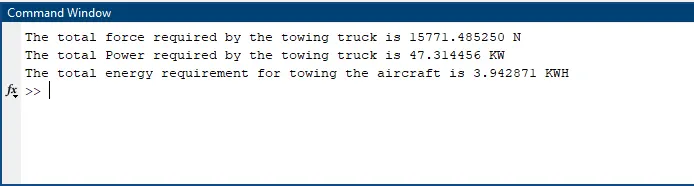
OBJECTIVE - 2:
SIMULINK MODEL TO CALCULATE THE ABOVE:
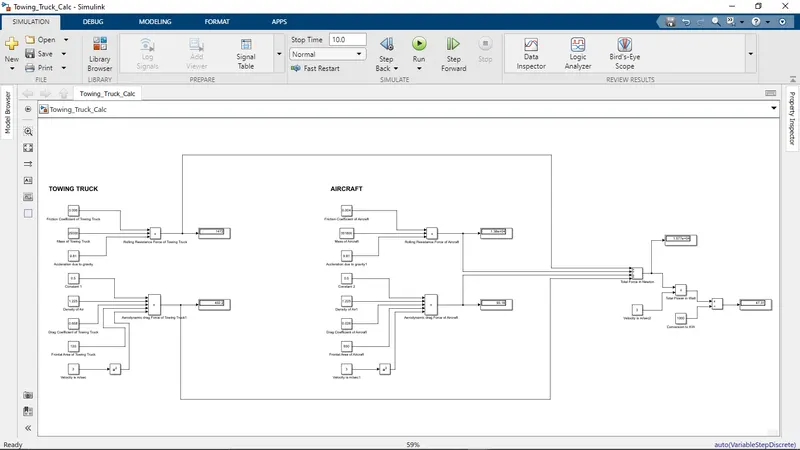
RESULTS:
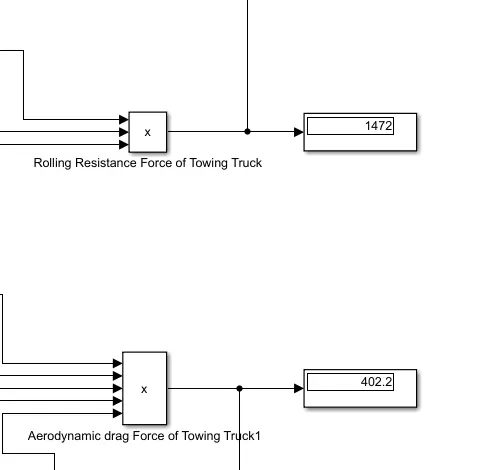
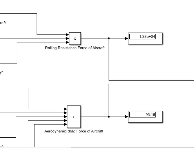
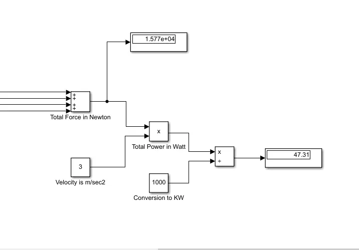
OBJECTIVE - 3:
TO DESIGN AN ELECTRIC POWER TRAIN:
DUTY CYCLE:
- Let's assume the capacity of the motor to be 60KW
- Motor Efficiency = 95%
- Shaft Power = 60*0.95 = 57 KW
- So, the Input Power = 57 KW
- Output Power = 47.314 KW
- Duty Cycle = Output Power / Input Power
- Duty Cycle = 47.314 / 57
- Duty Cycle = 0.83
- Duty Cycle = 83%
POWERTRAIN BLOCK DIAGRAM:
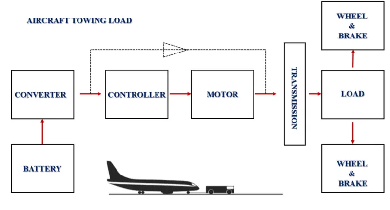
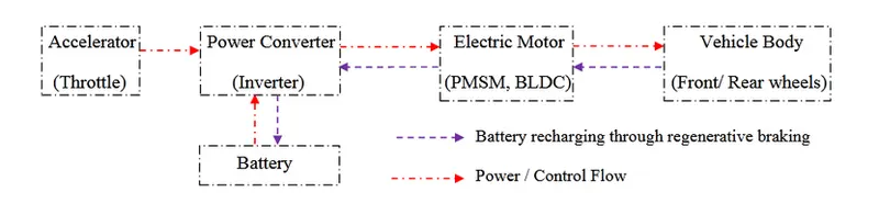
DC7 EXAMPLE:
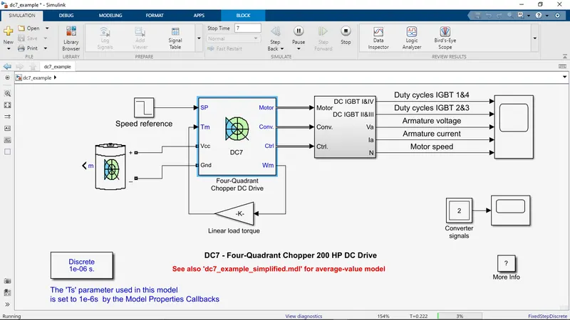
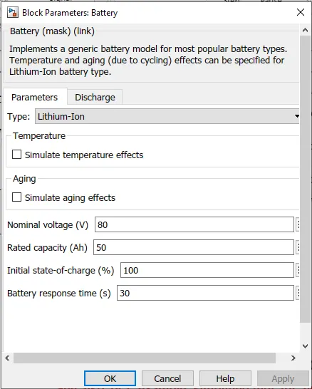
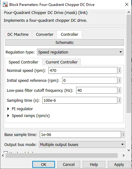
RESULTS:
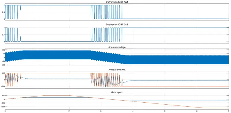
OBJECTIVE - 4:
DESIGNING THE PARAMETERS IN EXCEL:
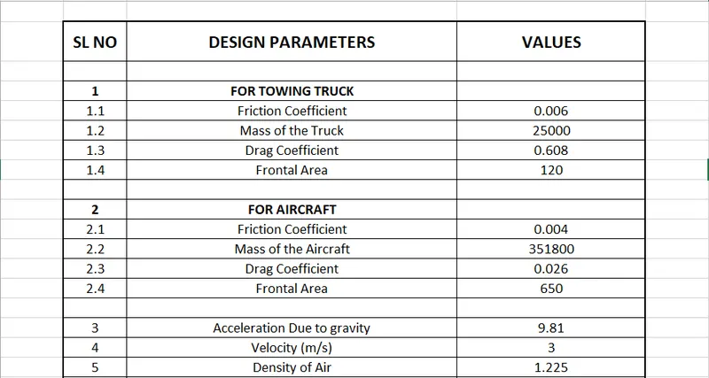
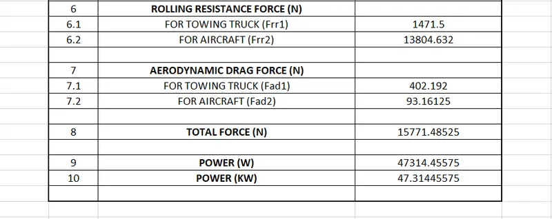
CONCLUSION:
- The total weight of various aircrafts is searched and listed out.
- The difference between ground speed and air speed is mentioned above.
- We found out why the aircraft engine power is not used to move the aircraft on the ground when coming to the runway for take-off.
- We explained how an aircraft is pushed to the runway during take-off.
- We explained in detail about the take-off power, tire design, rolling resistance, tire pressure and brake forces during landing.
- We calculated the total force and power required by the Towing truck in order to push/pull the Aircraft to the runway during take-off by assuming the required constant values.
- The same calculation is represented using a MATLAB code.
- A SIMULINK model is developed in order to calculate the above forces and power required by the Towing Truck to push/pull the Aircraft to the runway during take-off.
- A Powertrain is designed by changing the required blocks and values in order to represent the above force and torque and is designed and developed in such a way that the electric Towing Truck is able to push/pull the Aircraft to the runway during take-off.
- We also have created an Excel sheet calculator in order to calculate the design parameters for the above case.