Project-1: Powertrain for aircraft in runways
1 The maximum weight of the aircraft is shown in the table (ref:wikipedia)
2. Relative speed between the object and air which causes the aircraft to lift is called airspeed. Ground speed is a vector quantity so a comparison of the ground speed to the wind speed must be done according to rules for vector comparison.(Ref: https://www.grc.nasa.gov/www/k-12/airplane/move.html#:~:text=Airspeed%20is%20the%20vector%20difference,speed%20and%20the%20wind%20speed.&text=On%20a%20perfectly%20still%20day,less%20than%20the%20ground%20speed.)
3. Most aircraft cannot move in reverse manner since they dont have a reverse gear. Also more fuel is spent in taxing rather than towing.It also causes louder and noiser operation.
4. 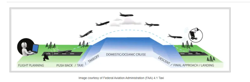
There are different movements of aircraft.
- Taxing: Taxiing refers to the movement of an aircraft on the ground, under its own power. The aircraft moves on wheels. The aircraft moves within the yellow line to avoid any collison with near by objects or buildings.
- Towing happens when the aircraft is towed by a land vehicle.
- The thrust to propel the aircraft forward comes from its propellers or jet engines. Steering is achieved by turning a nose wheel or tail wheel/rudder; the pilot controlling the direction travelled with their feet.
- Takeoff is the phase of flight in which an aircraft goes through a transition from moving along the ground (taxiing) to flying in the air, usually starting on a runway. Usually the engines are run at full power during takeoff.
- Climb: Following take-off, the aircraft has to climb to a certain altitude (typically 30,000 ft or 10 km) before it can cruise at this altitude in a safe and economic way. A climb is carried out by increasing the lift of wings supporting the aircraft until their lifting force exceeds the weight of the aircraft. Once this occurs, the aircraft will climb to a higher altitude until the lifting force and weight are again in balance. The increase in lift may be accomplished by increasing the angle of attack of the wings, by increasing the thrust of the engines to increase speed (thereby increasing lift), by increasing the surface area or shape of the wing to produce greater lift, or by some combination of these techniques.
- Cruise is the level portion of aircraft travel where flight is most fuel efficient. It occurs between ascent and descent phases and is usually the majority of a journey.
- A descent during air travel is any portion where an aircraft decreases altitude either for landing, bad traffic or climate etc.
- Landing is the last part of a flight, where the aircraft returns to the ground.
5. The amount of power that an engine is allowed to produce for a limited period of time for takeoff. The use of takeoff power is usually limited to 5 min for reciprocating engines and up to 2½ min for gas turbine engines.
An aircraft tire is designed to withstand extremely heavy loads for short durations.The number of tires required for aircraft increases with the weight of the aircraft, as the weight of the airplane needs to be distributed more evenly. Aircraft tire tread patterns are designed to facilitate stability in high crosswind conditions, to channel water away to prevent hydroplanning and for braking effect.R olling resistance occur by friction between tire and ground.When the aircraft is moving in ground by taxing or towing at that time rolling resistance force is act against the traction force of aircraft.
The tire pressure of aircraft is very high to minimize the rolling resistance and withstand the weight. Usually tire pressure is 190 to 320 psi based on aircraft types it’s varies.
A large braking force is required for the aircraft to stop. There is deedicated brake unit on each wheel to stop the aircraft.
Part B:
6,. Excel file for calculation is attached.
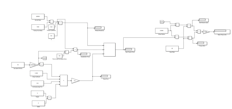
7. The simulink model for total traxtive effort calculation is shown below.
7. The components of EV powertrain includes
- Battery pack - which consist of lithium ion or Lead acid battery and stores the energy required to run the vehicle.
- DC- AC Converter- DC supplied by battery pack is converted to AC and supplied to the motor.
- Electric Motor- converts electrical energy to mechanical energy required for the movement of vehicle.
- ON baord charger- controls the amount of current flowing through the battery.
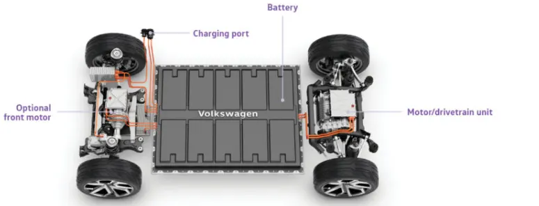
Assumptions are require which is below table shows.
|
motor assumed parameter |
|
|
Radius of tyre tug |
0.653m |
|
gear ratio |
8 |
|
transmission efficiency |
87% |
|
motor efficiency |
95% |
|
battery capacity |
380v |
|
power required to aircraft |
261.8kw |
|
force required to aircraft |
31.4kN |
|
speed of vehicle |
8.33m/s |
|
towing operation |
30min |
Velocity of vehicle = 8.33m/s
Force is required to push/pull aircraft = 31.4KN
Power required = 261.8 KW
Let us assume,
Radius of tyre for tug = 0.635m
Gear ratio = 8
Transmission efficiency(nt) = 87%
Motor efficiency(nm) = 95%
Torque required for wheel(Tw) = total force*radius in meters
= 31.4*0.63
= 19.782KNm
Motor torque = wheel torque/(gear ratio*nt)
= 19.782/(8*0.87)
= 2.841 KNm
For nm =95%
Required motor torque = 2.841/0.95
= 2.99KNm
Similarly for power,
Power required by motor considering all efficiencies = 261.8/(0.87*0.95)
= 316.75kw
Assume time duration of towing operation is
Total energy consumed = 316.75*0.5
= 158.37 kWh
If we consider battery capacity = 380kw is used by towing vehicle then,
Duty cycle = required power / rated power
= 316.75/380
= 0.833
Therefore the controller will be able to provide a duty cycle ranging from 0 to 83% in order to control towing speed.
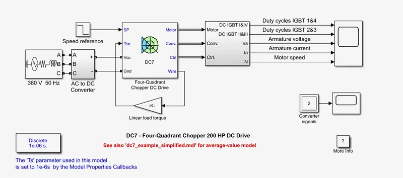
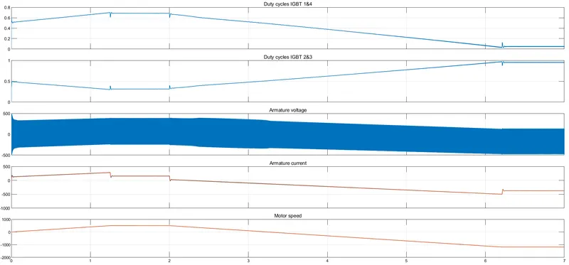
Simulation of four quadrant DC chopper drive 200HP drive is shown below
200 HP DC motor is separately excited with a constant 150 V DC field voltage source. The armature voltage is provided by an IGBT converter controlled by two PI regulators. The converter is fed by a 515 V DC bus obtained by rectification of a 380 V AC 50 Hz voltage source. In order to limit the DC bus voltage during dynamic braking mode, a braking chopper has been added between the diode rectifier and the DC7 block.
The first regulator is a speed regulator, followed by a current regulator. The speed regulator outputs the armature current reference (in p.u.) used by the current controller in order to obtain the electromagnetic torque needed to reach the desired speed. The speed reference change rate follows acceleration and deceleration ramps in order to avoid sudden reference changes that could cause armature over-current and destabilize the system. The current regulator controls the armature current by computing the appropriate duty ratios of the 5 kHz pulses of the four IGBT devices (Pulse Width Modulation). For proper system behaviour, the instantaneous pulse values of IGBT devices 1 and 4 are opposite to those of IGBT devices 2 and 3. This generates the average armature voltage needed to obtain the desired armature current. In order to limit the amplitude of the current oscillations, a smoothing inductance is placed in series with the armature circuit.