Project-1: Powertrain for aircraft in runways
POWERTRAIN FOR AIRCRAFT IN RUNWAYS
AIM:
- To search and list out the total weight of various types of aircrafts.
- To know about ground speed and air speed and conclude the difference if any.
- To study why is it not recommended to use aircraft engine power to move it on the ground at Airport.
- To understand how an aircraft is pushed to runway when its ready to take off
- To learn about take off power, tyre design, rolling resistance, tyre pressure, brake forces when landing.
- A. With necessary assumptions to calculate the force and power required to push / pull an aircraft by a towing vehicle.
B. To develop the model for the calculated force and power using Simulink.
- A. To design an electric powertrain with type of motor, it’s power rating, and energy requirement to fulfill aircraft towing application in Simulink. Estimate the duty cycle range to control the aircraft speed from zero to highest by Making all required assumptions and prepare a table of assumed parameters by also drawing a block diagram of powertrain.
B. To design above the parameters in excel sheet.
1) To search and list out the total weight of various types of aircrafts.
- The aircraft gross weight is the total aircraft weight at any moment during the flight or ground operation.It ia also known as all-up weight(AUW).
- An aircraft's gross weight may vary during a flight due to reduce in payload, fuel consumptionn in-flight refueling, water consumption, etc.
- When releasing its brakes, the gross weight of an aircraft is equal to its takeoff weight. During flight, an aircraft's gross weight is referred to as the en-route weight or in-flight weight.
- For efficient and safe operation of aircraft there are many factors that need to be in considerations. Among all the vital factors are proper weights and balance control.
- The manufacturer provides the aircraft operator with the empty weight of the aircraft and the location of its empty weight center of gravity (EWCG) at the time the certified aircraft leaves the factory. From these design considerations the maximum allowable weight on aircraft is be decided.
Manufactures's Design Weight limitation:
- However, the maximum operational weight may be less than the maximum allowable weight due to conditions of wet grass or water on the runway and also limited by the length of the runway.
- The structural weight limits are based on aircraft maximum structural capability and define the envelope for the CG charts. Aircraft structural weight capability is established during aircraft design and certification.
Maximum Design Taxi-Weight(MDTW):
- The maximum design taxi weight is the maximum certificated design weight for aircraft ground manoeuvres which is limited by aircraft strength and airworthiness requirements. It is also known as maximum design ramp weight (MDRW).
Maximum Design Takeoff Weight(MDTOW):
- It is the maximum certificated design weight when the brakes are released for takeoff and is the greatest weight for which compliance with the relevant structural and engineering requirements has been demonstrated by the manufacturer.
Maximum Design Landing Weight(MDLW):
- It is the maximum certificated design weight for landing limited by aircraft which depends on the landing gear strength or the landing impact loads on certain parts of the wing structure.
MDLW < MDTOW < MDTW
- The difference between the maximum taxi/ramp weight and the maximum take-off weight depends on the size of the aircraft, the number of engines, APU operation, and engines/APU fuel consumption, and is typically assumed for 10 to 15 minutes allowance of taxi and run-up operations.
Maximum Design Zero-Fuel Weight (MDZFW):
- It is the maximum certificated design weight of the aircraft less all usable fuel and other specified usable agents as limited by aircraft strength.
- In simple we can say that it is the maximum weight permitted before usable fuel and other specified usable fluids are loaded in specified sections of the airplane.
- The weight difference between the MDTOW and the MDZFW may be utilized only for the addition of fuel.
- If the addition of weight to the MDZFW will not lead to the limitation of Strength being exceeded.
Minimum Flight Weight(MFW):
- It is the weight of the aircraft as built and includes the weight of the structure, power plant, furnishings, installations, systems and other equipment that are considered an integral part of an aircraft before additional operator items are added for operation.
- Minimum certificated weight for flight as limited by aircraft strength and airworthiness requirements.
Effects Of Weight:
Some of the problems caused by overloading an aircraft are:
- The aircraft will need a higher takeoff speed, which results in a longer takeoff run.
- Both the rate and angle of climb will be reduced.
- The cruising speed will be reduced and range will be shortened.
- Maneuverability will be decreased.
- A longer landing roll will be required because the landing speed will be higher.
- Excessive loads will be imposed on the structure, especially the landing gear.
Types of aircrafts with their weights:
a) Lighter-Than-Air – balloons or airships:
- The passage through the air of a ballon that contains a buoyant gas, such as helium or heated air, for which reason it is also known as lighter-than-air free flight
- Manned balloons have a basket, or gondola, attached below the balloon for the pilot and passengers. A simple harness or boatswain’s chair has become popular for solo flights.
- By adjusting the ascent and descent of a balloon through the air, a pilot can take advantage of available winds to guide the course of the balloon over the surface of Earth.
- The first untethered manned balloon ascent took place on November 21, 1783.
- Airship also called dirigible, a self-propelled lighter-than-air craft.
- Three main types of airships or dirigibles have been built: nonrigids, semirigids, and rigids.
- All three types have four principal parts:
a)cigar-shaped bag or baloon that is filled with a lighter-than-air gas
b)car or gondola that is slung beneath the balloon and holds the crew and passengers
c)engines that drive propellers and
d)horizontal and vertical rudders to steer the craft.
- Nonrigids are simply balloons with cars attached by cables if the gas escapes, the balloon collapses.
- Semirigids depend on the internal gas to maintain the balloon’s shape, but they have a structural metal keel that extends longitudinally along the balloon’s base and supports the car.
- Rigids consist of a light framework of aluminum-alloy girders that is covered with fabric.
- The usual gases used for lifting airships are hydrogen and helium. Hydrogen is the lightest gas and has great lifting capacity, but it is highly flammable and causes disasters. Helium is not as buoyant but is far safer than hydrogen because it does not burn.
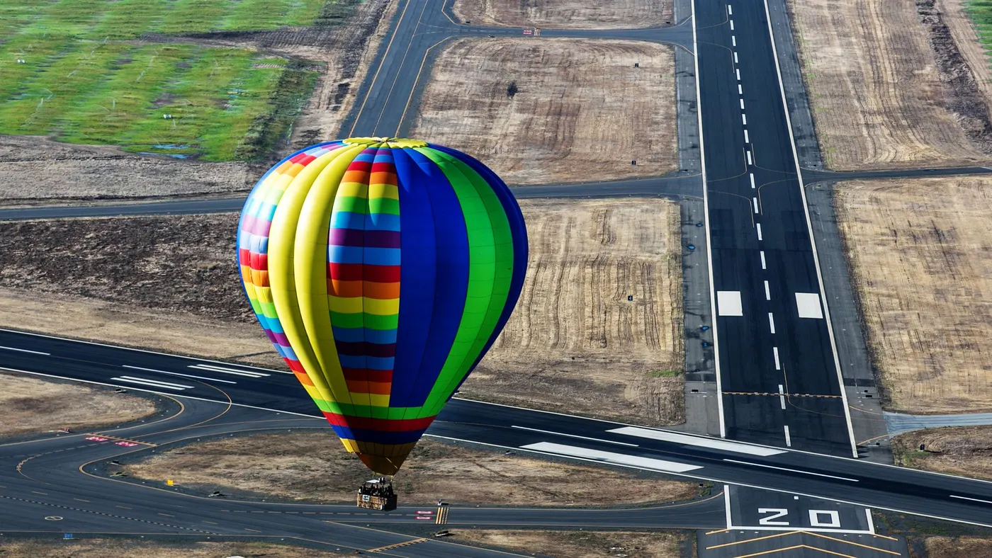
Weight of air-ballons can vary from 400kg to 850kg with any passenger and fuel.
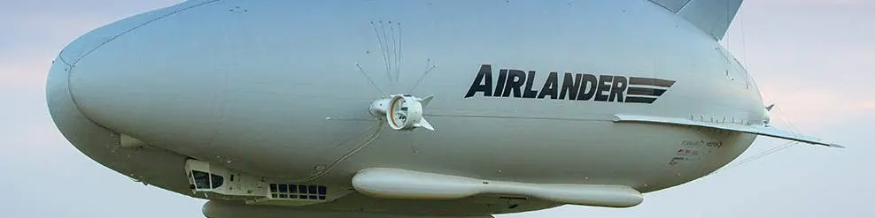
Gross weight of 20,000 kg and maxmum wieght of 33,285kg.
b) Powered Parachutes – land or sea
- A powered parachute is a type of aircraft that consists of a parafoil with a motor and wheels.It is also called as motorized parachute or paraplane.
- Powered parachute as a powered aircraft comprised of a flexible or semi-rigid wing connected to a fuselage so that the wing is not in position for flight until the aircraft is in motion.
- The fuselage of a powered parachute contains the aircraft engine, a seat for each occupant and is attached to the aircraft's landing gear.
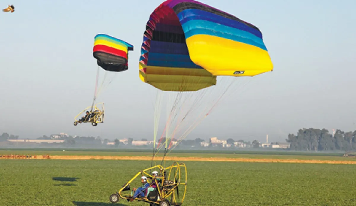
The empty weight of a PPC can range from 90–225 kg and payload can be upwards of 225 kg.
c) Weight-Shift-Control – land or sea:
- A weight-shift control is a flexible wing type aircraft consists of a fabric-covered wing attached to a tubular structure that has wheels, seats, and an engine and propeller.
- The wing structure is tubular with the fabric covering creating the airfoil shape.
- The shape of the wing varies among the different models of weight-shift control aircraft being produced, but a delta shaped wing is a very popular design.
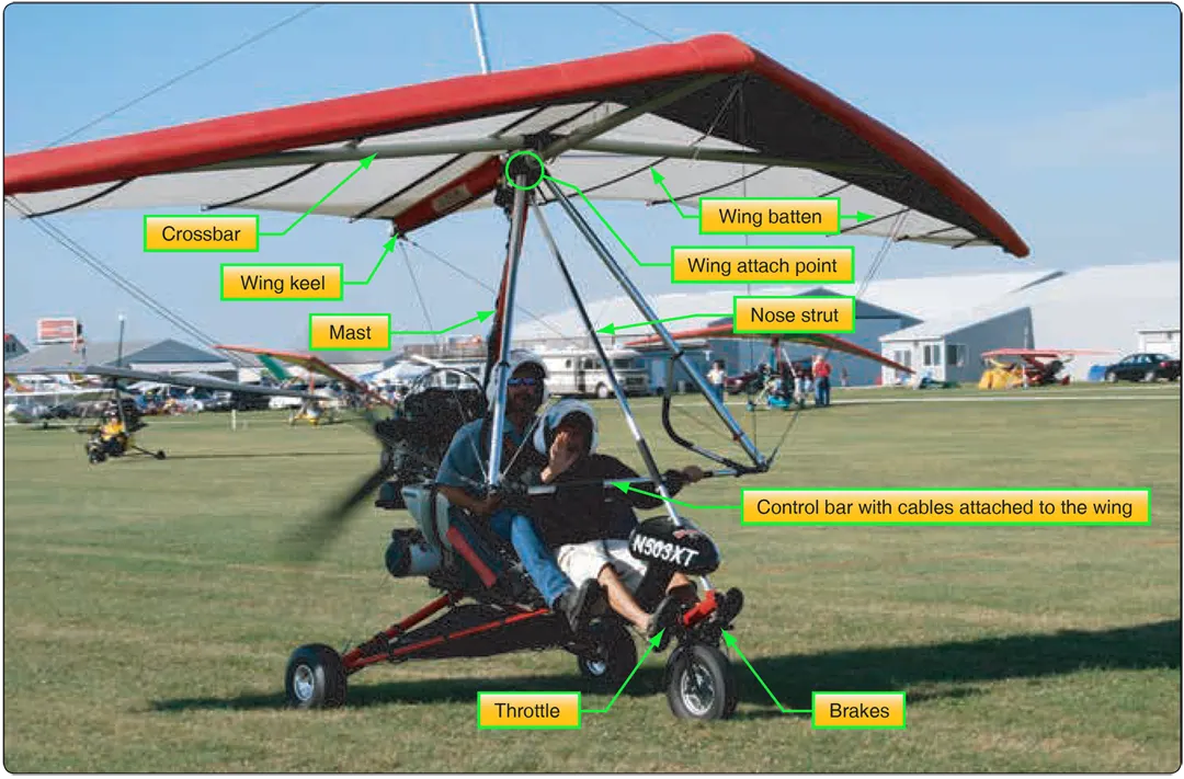
The weight of the aircraft can be 3,900kgs without a passenger.
d) Rotorcraft – helicopter or gyroplane:
- Helicopter is the most common rotorcraft. These are aircraft that feature engine-driven rotor that spins during flight with their spinning rotor and they can fly forwards, backwards, upwards and downwards.
- They have a spinning rotor that produces lift while simultaneously allowing pilots to control the helicopter.
- Gyroplanes considered as a vertical takeoff and landing vehicle having an engine-powered rotor.
- With the engine-powered rotor they operate much like helicopters.
- Gyrodynes don’t require a long runway to take off or land. The main difference between gyrodynes and helicopters is that the former features an auto-adjusting rotor that reduces the risk of stalling and other problems associated with helicopters.
Helicopters weigh from 135kg to 15,500kg without any payload.
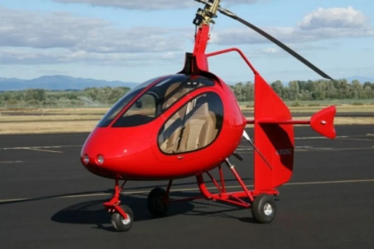
Weight of Gyroplane weight of 245kgs as empty and 450kgs gross weight.
e) Airplane – Single-engine land or sea or multi-engine land or sea:
- M28 Twin Turboprop: empty weight of 4,354kg and gross weight of 7,500kg.
- Bonanza A/G36: empty weight of 1,150kg and payload weight of 450kgs.
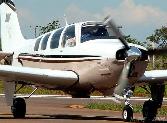
- MIG-25: 20,000kgs.
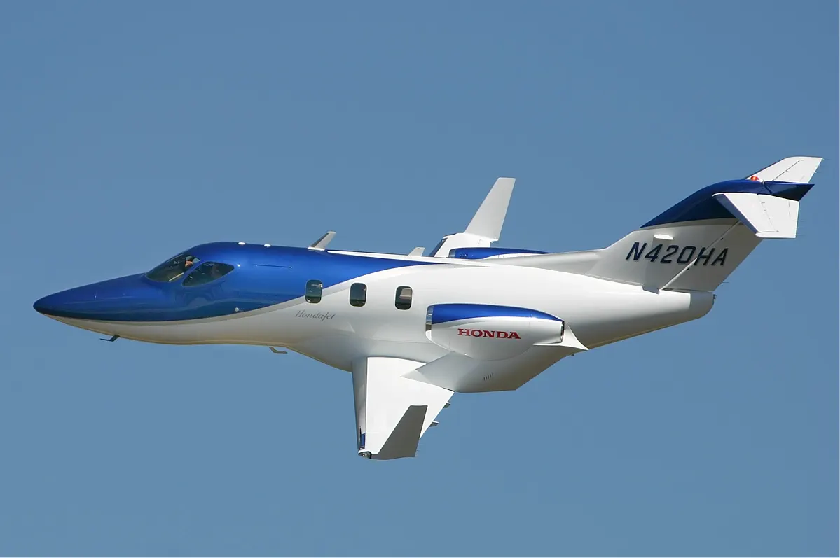
- Honda HA-420: 3,267kgs
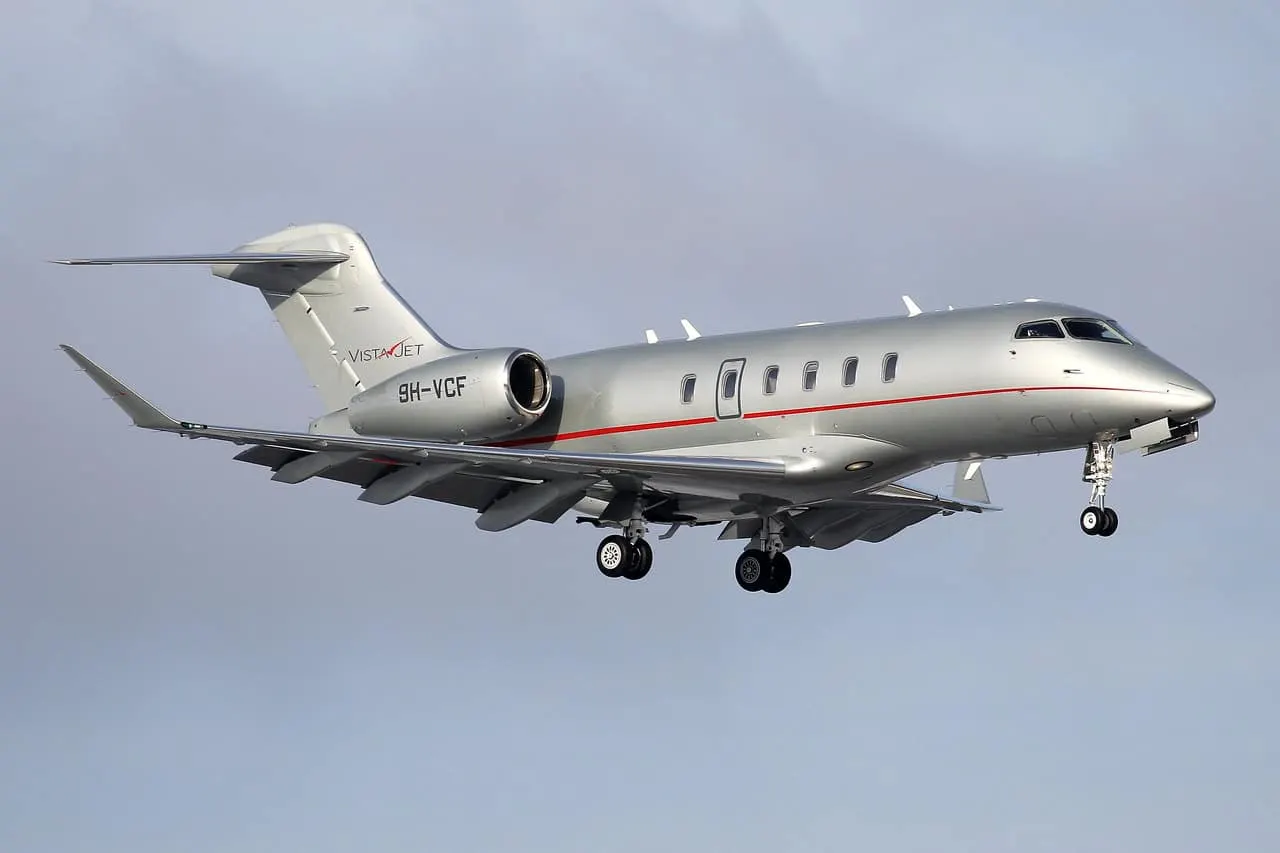
- Bombardier Challenger 350: 11,250kg
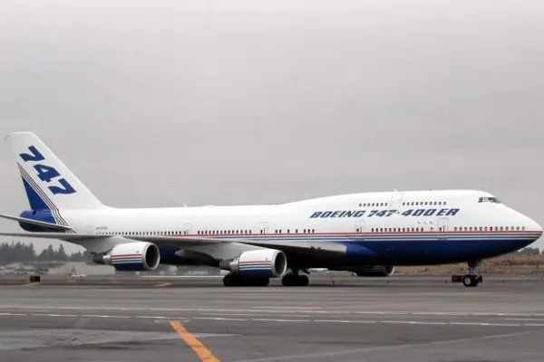
- Boeing 747-400: 1,83,500kg.
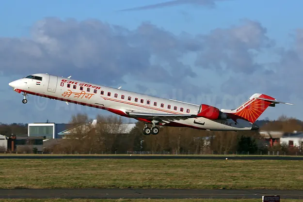
- VTR-RJB Bombardier CRJ 700: 70,00kg including payload and fuel.
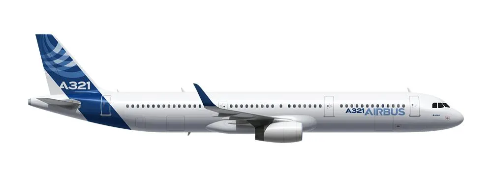
- Airbus A321: 48,500kgs.
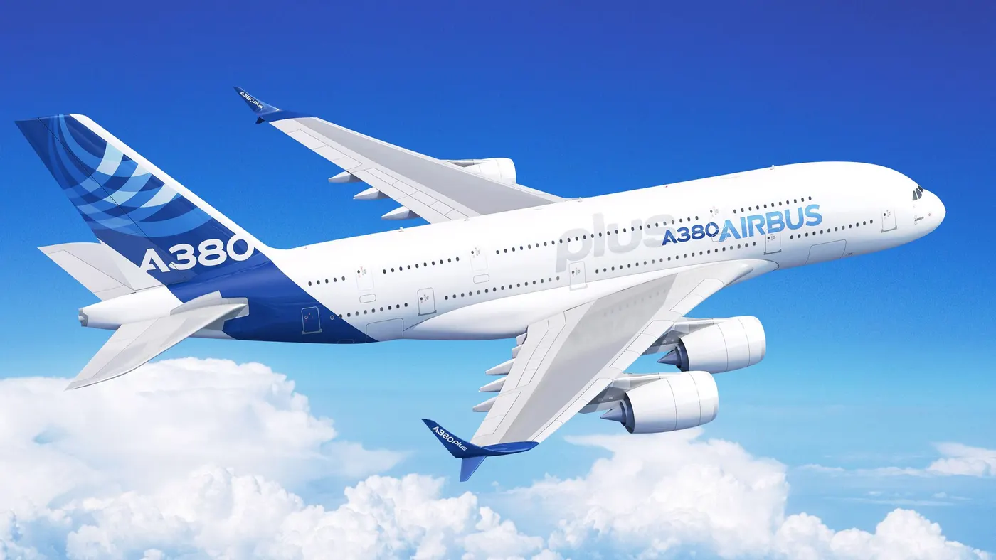
- Airbus A380: 2,77,000kgs.
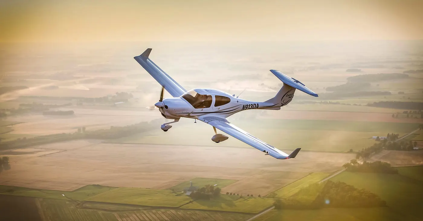
- Diamond DA40: empty weight of 900kg.
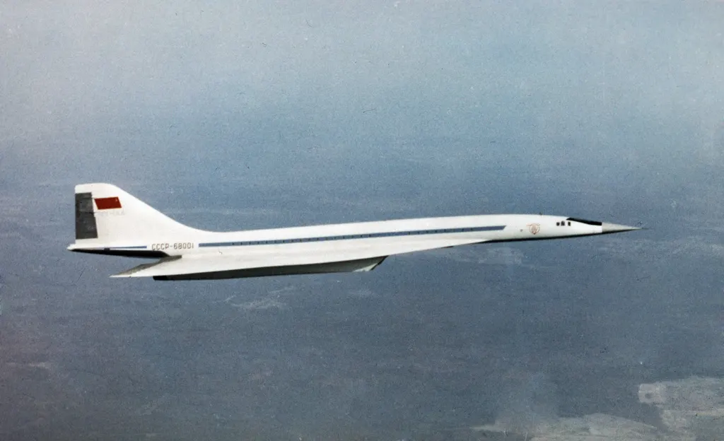
- Concorde: 78,700kgs.
- Tupolev TV-144: 85,00kgs.
References: https://stylesatlife.com/articles/types-of-aircrafts/
https://mediawiki.ivao.aero/index.php?title=Standard_aircraft_weight
2) To know about ground speed and air speed and conclude the difference if any.
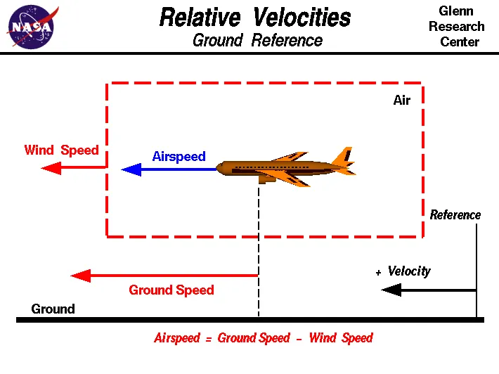
Ground Speed:
- Ground speed is the speed at which an aircraft is moving relative to the air it is flying. Aircraft heading vertically would have a zero ground speed.
- Ground speed can be determined by vector sum of aircraft's true speed and the current speed and direction; a a headwind subtracts from ground speed whereas tailwind adds.
- Winds flowing in other direction will have either headwind or tailwind along with the crosswinds.
Air Speed:
- Airspeed is the relative speed difference of of an aircraft and air.
- Airspeed cannot be directly measured from ground position, but must computed from vector difference of ground speed and wind speed.
- There are three different types of airspeeds:
a) Indicated airspeed: This is a simple airspeed indicator which is used as reference by the pilots in the cockpit for speed changes.
b) Calibrated airspeed:
- Calibrated airspeed is indicated airspeed corrected for instrument and positional errors.
- At certain airspeeds and with certain flap settings, the installation and instrument errors may total several knots.
- When flying at sea level under International Standard Atmosphere (ISA) conditions calibrated airspeed is the same as true airspeed. If there is no wind it is also the same as ground speed.

c) True speed:
- True airspeed is the speed of an aircraft relative to the air it's flying through.
- As we climb, true airspeed is higher than your indicated airspeed because at higher altitudes the pressure decreases, so for any given true airspeed as we climb, slowly air molecules will enter the pitot tube by which indicated airspeed will be less than true airspeed.
- So at 10,000 feet, true airspeed is roughly 20% faster than what you read off your airspeed indicator.
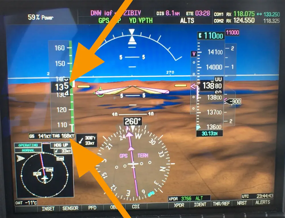
Airspeed and Windspeed comparision: Since aircraft operates on land as well as air we need to study the speed difference on ground and in air.
- The ground speed and airspeed usually change based on the wind speed.
- If the aircraft is flying in the same direction as the wind is blowing, the aircraft experiences tailwind, and its ground speed is higher than its airspeed.
- On the other hand, if the wind is blowing against the direction the aircraft is traveling in, the aircraft experiences headwind, and its ground speed is lower than its airspeed.
- Gravity plays a major role in increasing the aircraft's speed while descending.
- The relationship between airspeed and ground speed is fairly simple. Ground speed is simply the sum of airspeed and wind speed.
- For pilots, both airspeed and ground speed are very important. SInce it helps them make sure they are flying fast enough to take off, the second one helps them figure out how long it will take them to get from one place to another.
- On the other hand, if you are a passenger, you will only need to be concerned about the ground speed as that will tell you how fast are you flying from your origin to your destination.
Reference: https://www.grc.nasa.gov/www/k-12/airplane/Animation/airrel/anrela.html
3) To study why is it not recommended to use aircraft engine power to move it on the ground at Airport.
- For the movement on ground the aircraft can use it's own engine power which is knowing as taxing.
- Though many aircrafts are capable of moving in backward using reverse thrust which result in jest blast or prop wash which cause damage to the termial building or equipment.
- Engine close to the ground may inhail sand and derbis which causes damage to the engine.
- To avoid these circumstances a pushback truck is used to move the aircraft from one place to another in the airport by lifting the front wheel of the aircraft, this process is known as towing
Uncircumstances are caused due to unintended movement of aircraft which may damage to the engine.
- Loss of control can happen, during high power engine running. It not only effects the aircraft engine itself but also the aircrafts nearby.
- There is a chance of injury to the ground support personnel who may be work closely to the aircraft.
- It is easier for a truck driver to see the surrounding than th pilot who is sitting in the cockpit and also pushback driver has better knowledge about airport than the pilot.
- Towing will save the fuel of the aircraft and also reduces the impact on environment.
- Since the plsne engines make very loud sounds. When more than one plane will move simulatneously then that sound will not be pleasant for passengers and others near by the airport.
4) To understand how an aircraft is pushed to runway when its ready to take off.
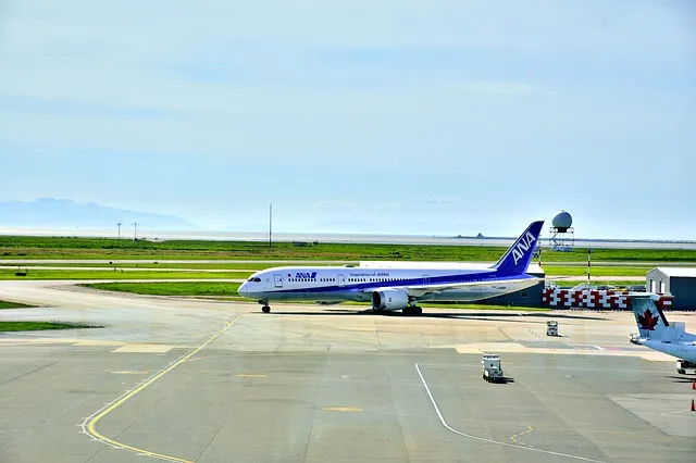
- Taxing and Towimg are the two ways to reach the runway.
Taxing:
- Taxiing is the movement of an aircraft on the ground by utilizing its own power.
- An airplane uses taxings to taxi from one place to another in the airport. For example when moving from a hangar to the runway.
- Taxing is recommended for the planes whcih has engines of low power since when high power engines taxied there may be chances of getting damaged.
Towing:
- The forward movement of an aircraft, usually with engines off, using the power of a specialised ground vehicle attached to or supporting the nose landing gear. It may occur for the movement of both in service and out of service aircraft. This is known as towing.
- Once the person in charge on the flight deck of the aircraft has given their confirmation of ‘brakes released’ to the person in charge of the ground crew vehicle who are to carry out the tow, the ground crew become responsible for the safe manoeuvring of the aircraft in accordance with any ATC clearence which may be required.
- The traditional method of allowing the ground vehicle to move an aircraft is to attach it to the aircraft nose landing gear by means of a towbar. These must be approved for use with a particular aircraft type and clearly marked as such since there is no universal towbar specification.
- An alternative method which is becoming more common for towing is the use of a specialised vehicle called a towbarless tug. This positions two low level ‘arms’ either side of the aircraft nose landing gear and these are used to engage with the aircraft gear leg and raise it slightly off the ground.
- All towing is subject to the observance of any AFM limits for maximum nose landing gear steering angle.
- The responsibilities of a ground crew team carrying out an aircraft tow include ensuring that no part of the aircraft structure will impact any fixed object, vehicle, or other aircraft.
- The ground crew should have intercom communication with the personnel on the flight deck and both parties should be able to listen to communications with ATC.
- In the absence from the flight deck of a pilot qualified on the aircraft type, The person in charge of the ground vehicle carrying out the tow will usually be responsible for obtaining any necessary ATC aircraft movement clearances.
- The key threat to aircraft towing operations is collision between the aircraft under tow and another aircraft. Two types of collision with potentially high risk outcomes exist
- A collision with a moving aircraft taking off or landing on an active runway whether or not the aircraft under tow has a valid ATC runway occupancy clearance.
- Impact damage to another stationary and unoccupied aircraft caused by undetected minor impact which not detected prior to either damaged aircraft departing on a flight.
- Ground Crews must be specifically made aware of both these risks and must be fully trained on both ATC practices and the towing of the particular aircraft type involved.
Aircraft towed by a tug
A Towbarless Tug
An article referred to : https://www.skybrary.aero/index.php/File:Towbarless_tug.jpg
5) To learn about take off power, tyre design, rolling resistance, tyre pressure, brake forces when landing.
Take off power:
- The pilot squeezes the thrust levers slightly forwards, advancing the engines to around 20% of their maximum power. All pilots scan the engine instruments for any anomalies and satisfied, the pilot uses their index finger to press the Take Off/Go Around (TOGA) button.
- With a whir of an electric motor, the auto throttle advances the thrust levers forward and sets the takeoff power. With a reassuring whine, the two massive engines under the wings are now set to work.
- As the aircraft reaches its critical speed, the pilot pulls gently back on the control column. The tail of the aircraft sinks down raising the nose into the air.
- For a moment, the aircraft seems to crouch, nose pointed up, poised, ready to launch skywards. Then the wings bite the air rushing over them and the aircraft eases into the sky.
Take-Off Run Available (TORA):
- The TORA is the distance from the point at which the aircraft can start its takeoff run to the point at which the the surface can no longer bear its weight. In most cases, this is equivalent to the length of the runway.
The Clearway:
- This is an area at the end of the TORA that is free from any obstructions exceeding 0.9 meters in height like buildings or trees. The aircraft can use this area in order to achieve the 35 feet screen height.
- The clearway may not be immediately obvious, as it is not defined by a paved surface. It can include an area of open ground or even water, so long as it is under the control of the airport. When you add the clearway to the TORA, this gives you the…
Takeoff Distance Available (TODA):
- The TODA is the total distance that the aircraft has to start its takeoff run and climb to the 35 feet screen height. On a runway without a Clearway, the TODA will equal the TORA.
Accelerate-Stop Distance Available (ASDA)
- The final distance that must be considered for takeoff performance is the ASDA. This is the distance of weight bearing surface available to the aircraft to accelerate and then come to a safe stop in the case of a rejected takeoff.
Take-Off performance:
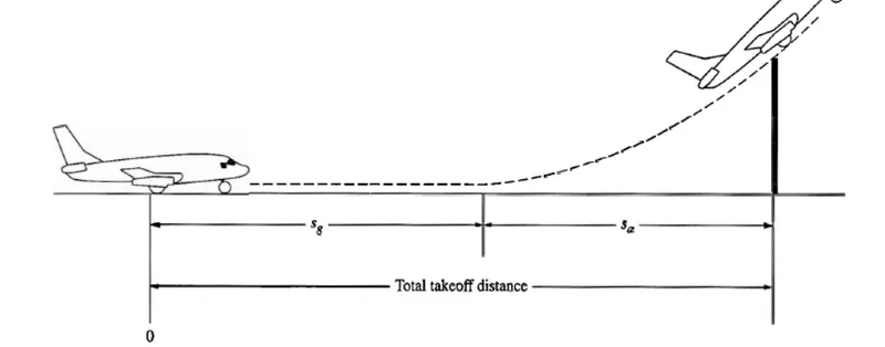
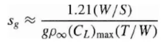
- An airplane is motionless at the runway is at 'O'. The pilot releases the brakes and pushes the throttle
to maximum takeoff power, and the airplane accelerates down therunway. At some distance from its starting point, the airplane liftsinto the air. The distance the airplane cover along the runwaybefore it lifts into the air is called the ground roll (sg). - The total takeoff distance also includes the extra distance covered over the ground after the airplane is airborne but before it clears an obstacle of 50 ft for military aircraft and 35 ft for commercial aircraft. This is denoted by sa. The sum of sg and sa is the total takeoff distance.
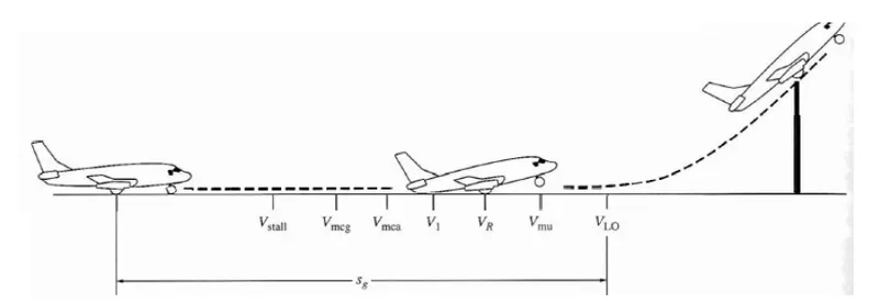
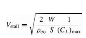
- As the airplane accelerates from zero velocity, at some point it will reach the stalling velocity VStall.
- The airplane continues to accelerate until it reaches the minimum control speed on the ground, Vmcg. This is the minimum velocity at which enough aerodynamic force can be generated on the vertical fin with rudder deflection.
- While the airplane is still rolling along the ground to produce a yawing moment sufficient to counteract that produced when there is an engine failure for a multiengine aircraft.
- If the airplane were in the air the minimum speed required for yaw control in case of engine failure is
slightly greater than Vmcg this velocity is called the minirnum control speed in the air, Vmca. - The airplane continues to accelerate until it reaches the decision speed, V1. This is the speed at which the pilot can successfully continue takeoff even though an engine failure would occur at this point.
- If an engine fails before V1 is achieved, the takeoff must be stopped. If an engine fail after V1 is reached, the takeoff has to be completed.
- The airplane continues to accelerate until the takeoff rotational speed, VR is achieved. At this velocity, the pilot initiates for elevator deflection a rotation of the airplane in order to increase the angle of attack and to overcome the weight.
- The angle of attack necessary to overcome the weight may not be achievable because the tail may drag the ground. If the rotation of the airplane is limited by ground clearance for the tail, the airplane must continue to accelerate while rolling along the ground after rotation is achieved. This speed is called the minimum unstick speed, denoted by Vus.
- The angle of attack after rotation is slightly less than the maximum allowable by tail clearance, and the airplane continues to accelerate to a slightly higher velocity, called the lift off speed, denoted by VLO. This is the point at which the airplane actually lifts off the ground. The total distance covered along the ground to this point is the ground roll sg.
- Generally VLO=1.1 Vstall.
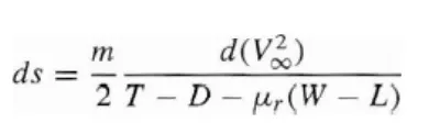
Tire Design:
- When it comes to safety, tyres are one of the most important components of aircraft. They help to absorb the shock of landing and provide cushioning, necessary traction for braking and stopping of an aircraft.
- An aircraft tyre is designed to withstand extremely heavy loads while landing, take off, taxing, and parking.
- The number of wheels required for aircraft increases with the weight of the aircraft, as the weight of the aeroplane needs to be distributed more evenly.
- A Boeing 737NG & 737MAX uses 6 wheels, Boeing 787 uses 10 wheels, Boeing 777 uses 14 wheels and Airbus A380 uses 22 wheels.
- The main purpose of the tires are:
- They support the weight of an aircraft while it is on the ground.
- It also provides the necessary traction for braking and stopping of an aeroplane.
- Tyre also helps to absorb the shock of landing and provide cushioning the roughness of takeoff, roll-out, and taxi operations.
Design and Construction of tire:
- Unlike an automobile or truck tyre, it does not have to carry a load for a long period. An aircraft tyre absorbs the high impact loads of landing and it’s operating at high speeds for a short time when required.
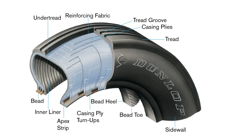
- Two types of tires are used in aircraft applications — bias-ply tires and radial tires.
Bias-ply construction:
- Bias-ply tires are popular choices for aircraft tires because of their durability and retreadability.
- Tread: The tread is made of rubber mixed with other additives to obtain the desired level of toughness, durability, and resistance to wear. The tread pattern is designed to aircraft operational requirements, with the ribbed tread design used widely due to its good traction under varying runway conditions.
- Sidewall: The sidewall is a protective layer of rubber that covers the outer casing ply. It extends from the tread edge to the bead area.
- Tread Reinforcing Ply: One or more layers of fabric that strengthens and stabilizes the tread area for high-speed operation and for buffing purpose while tires are retreaded.
- Buff Line Cushion: The buff line cushion is made of rubber compound to enhance the adhesion between the tread reinforcing ply and the breakers or casing plies.
- Breakers: Integral part of casing which reinforcing plies of rubber-coated fabric placed under the buff line cushion to protect casing plies and strengthen and stabilize the tread area.
- Casing Plies: Alternate layers of rubber-coated fabric provide the strength of the tire.
- Apex Strip: A wedge of rubber affixed to the top of the bead bundle.
- Flippers: Layers of rubberized fabric that help anchor the bead wires to the casing and improve the durability of the tire.
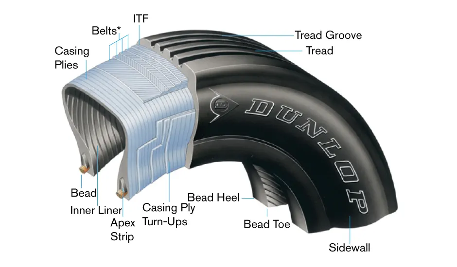
Radial-ply tire:
- They have few components similar to same sized and small size bias ply tires. Components that differ from bias-ply construction as follows:
- Overlay: A layer of reinforcing rubber coated fabric placed on top of the belts to aid in high speed operation.
- Belt Plies: A composite structure that stiffens the tread area for increased landings. The belt plies increase the tire strength in the tread area.
- Casing Plies: As in bias-ply tires, the casing plies are layers of rubber-coated fabric. However, unlike those in bias plies that run at opposite angles to one another, radial plies run radially from bead to bead.
- Chippers: The chippers are layers of rubber-coated fabric applied at diagonal angles that improve the durability of the tire in the bead area.
Imporatnt parameter considerations of tire:
- Retreading – It is method of restoring a worn tyre by renewing the tread area or by renewing the tread area plus one or both sidewalls. Repairs are included in the tyre retreading process.
- Load Rating – Load rating is the maximum permissible load at a specified inflation pressure.
- Ply Rating – Ply Rating is used to identify the maximum recommended load rating and inflation pressure for a specified tyre. Main rating for tyre strength.
- Speed Rating – The speed rating is the maximum takeoff speed to which the tyre has been tested.
- Skid Depth – Skid depth is the distance between the tread surface and the deepest groove as measured in the mould.
- Tyre growth is the increase in the size of the tyre due to centrifugal forces at high speed.
- Chines are also called deflectors. Chine tyre used on the nose wheel of aircraft, specially fuselage-mounted jet engines. It diverts runway water away from the engine inlets.Chines are circumferential protrusions that are moulded into the sidewall of nose tyres that deflect water sideways to help reduce excess water ingestion into the engines.
- All commercial aircraft tyres approved under FAA Requirement Technical Standard Order (TSO) C62. A TSO is a minimum performance standard for specified materials, parts, and appliances used on civil aircraft.
Rolling Resistance:
-
The force that resists the motion of a body rolling on a surface is called the rolling resistance or the rolling friction.
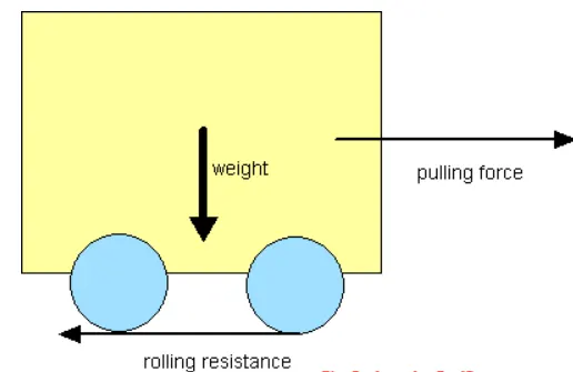
- The rolling resistance can be expressed by the generic equation:
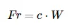
where, Fr = rolling resistance or rolling friction (N, lbf),c = rolling resistance coefficient - dimensionless
W = m ag = normal force - or weight - of the body (N), m = mass of body (kg, lb),
ag = acceleration of gravity (9.81 m/s^2).
- The rolling resistance can alternatively be expressed as
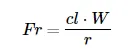
where, cl = rolling resistance coefficient - dimension length, r = radius of wheel (mm).
| Rolling Resistance Coefficient | ||
|---|---|---|
| c | cl (mm) | |
| 0.001 - 0.002 | 0.5 | railroad steel wheels on steel rails |
| 0.001 | bicycle tire on wooden track | |
| 0.002 - 0.005 | low resistance tubeless tires | |
| 0.002 | bicycle tire on concrete | |
| 0.004 | bicycle tire on asphalt road | |
| 0.005 | dirty tram rails | |
| 0.006 - 0.01 | truck tire on asphalt | |
| 0.008 | bicycle tire on rough paved road | |
| 0.01 - 0.015 | ordinary car tires on concrete, new asphalt, cobbles small new | |
| 0.02 | car tires on tar or asphalt | |
| 0.02 | car tires on gravel - rolled new | |
| 0.03 | car tires on cobbles - large worn | |
| 0.04 - 0.08 | car tire on solid sand, gravel loose worn, soil medium hard | |
| 0.2 - 0.4 | car tire on loose sand | |
Tire pressure:
- Aircraft tires are designed to withstand extremely heavy loads for short durations, with number of tires increasing with the weight of plane in order to better distribute the weight.
- Many tests being carryied out of airliner aircraft tires have shown that they are able to withstand pressures of maximum 800psi before bursting.
There are 2 hazarss associated with tires:
- Deflation: the tire deflates in a controlled manner with minimal direct consequence to other systems.
- Explosive break-up: the tire deflates or breaks-up in an uncontrolled manner with signifiacnt probability of secondary damage to the other unrelated systems.
The hazards are based on 4-distinct periods of aircraft operations.
- Ground operation.
- Take-off
- Post take-off
- Landing.
Landing:
- A number of issues may arise during the landing with deflated tire.
- Handling issues may arise during the landing roll-out phase and in severe cases may cause the aircraft to depart the prepared surface.
- Landing with a deflated tire will put additional strain on remaining tires, with an increases potential for one or more subsequently suffer an explosive deflation due to over stress.
- The implication of secondary damage will high and potential for rapid aircraft arrest and evacuation is important.
Brake forces when landing:
- Typically aircraft lands at a speed of 250kmph, so it is necesary to reduce the speed to a minimum stipulation time to bring to the rest.The breaking devices used are:
- Wheel brakes(Including Anti-skid system and Anti-brake system)
- Spoilers.
- Reverse Thrust.
Wheel brakes:
- Aircraft brakes stop a moving aircraft by converting its kinetic energy to heat energy by means of friction between rotating and stationary discs located in brake assemblies in the wheels.
- Brakes provide this critical stopping function during landings to enable airplanes to stop within the length of the runway.
- They also stop aircraft during rejected takeoff events the airplane is rolling down the runway before it lifts off from the ground due to engine failure, tire blowout, other system failure or direction from air traffic control.
- The most common type of brake used on aircraft is the disc brake which functions by exploiting friction between rotating and stationary discs inside the brake.
- Upon receiving a command signal to brake from the pilot foot pedal or from the autobrake system, actuators in the brake move a piston to squeeze the discs together, generating a frictional force that slows the rotation of the wheel.
- The friction between the discs generates heat as the aircraft’s kinetic energy is converted to heat energy which act as heat sink tremendous amounts of heat as the aircraft sheds kinetic energy.
- The discs are mounted on a carrier assembly consisting of a torque tube, which resists and transmits brake torque to the landing gear structure.
- Sandwiched together between the carrier assembly housing and a backing plate, the discs are arranged in an alternating pattern of rotors and stators.
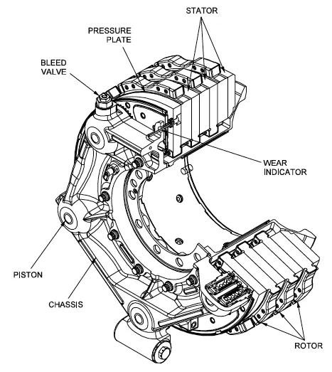
- The stators are keyed to the torque tube and are thus held stationary since the torque tube is connected to the axle and landing gear structure.
- Cylindrical spaces within the carrier assembly hold actuator pistons. Braking occurs as piston force squeezes the discs together.
- During each application of the brakes, disc material is worn away by frictional forces. A wear indicator in the form of a pin that protrudes out of the carrier assembly indicates the thickness of the stack of discs.
- A major design point around which aircraft brakes are designed is the worst-case scenario of rejected takeoff (RTO) at the maximum rolling speed V1, known as the decision speed.
- The most common aircraft brake disc material until around 1963 was steel.Carbon brakes became widely available for commercial airplanes starting in the 1980s.
- Brake actuators perform the critical task of squeezing discs together to generate the frictional forces that convert the aircraft’s kinetic energy of motion into heat to stop the aircraft. Most brake actuators on commercial aircraft are hydrallic.
- The large amount of heat generated during aircraft braking is dissipated by means of passive or active cooling.
- Passive cooling occurs due to natural conduction of heat through the disc material and to surrounding components, radiation of heat off the brake and wheel assembly, and convection as air flows past and through the brake assembly.Active cooling is achieved by using fans that force air through the brakes.
- Modern commercial aircraft are equipped with an autobrake system that controls the deceleration of the aircraft by automatically optimizing the application of brake force independent of pilot operation of the brake pedals to minimize stopping distance, reduce pilot workload and smooth braking action.
- Similar to anti-lock brakes on an automobile, skid control systems prevent wheel lockup. They minimize stopping distance and prevent the negative effects of skidding on tires such as unnecessary tire wear and blowout.
References:
https://webstor.srmist.edu.in/web_assets/srm_mainsite/files/downloads/class17-2012.pdf
https://www.aviationhunt.com/aircraft-tyre-construction/
https://www.engineeringtoolbox.com/rolling-friction-resistance-d_1303.html
https://insights.globalspec.com/article/12903/how-do-aircraft-brakes-work
6) A. With necessary assumptions to calculate the force and power required to push / pull an aircraft by a towing vehicle.
B. To develop the model for the calculated force and power using Simulink.
- Assuming average parameters of the plane Force and Power requirements by towing vehicle are calculated.
- Mass considerations:
Mass of the aircraft(including payload) = 2,27,000kgs.
Mass of push back = 25,000kgs.
Rolling resistance Force:
Co-efficient of rolling resistance 
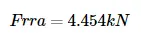
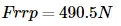
Force of rolling resistance 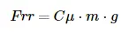
Aircraft Frra: 
Pushback Frrp: 
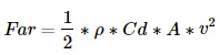
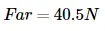
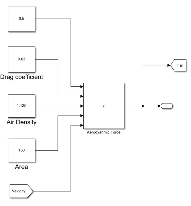
Aerodynamic Drag Force:
Drag Co-efficient(Cd) = 0.03
Air density(rho) = 1.125 (kg/m^3)
Frontal Area(A) = 150 m^2
Velocity of towing vehicle(v) = 14.4kmph=4(m/s)

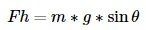
Hill Climbing Force:
Assumptions made are:
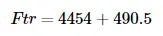
- The high climbing force is zero since the runway of the aircraft will be flat so we can neglect it.
- We can also neglect the areodynamic force since the speed is very less.
Total Tractive Force:


Total Power required:

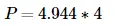
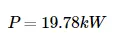
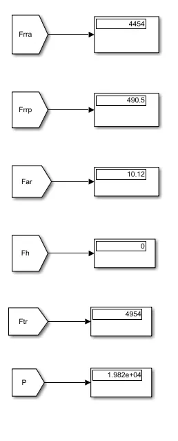
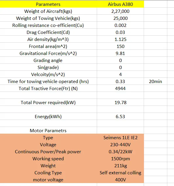
- The minimum power reqiured by the towing vehicle to push/pull the aircraft is 19.78kW at 4m/sec.
B) To make a simulink model for the above calculated Force and Power.
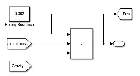
Rolling Resistance Force of Aircraft subsystem:
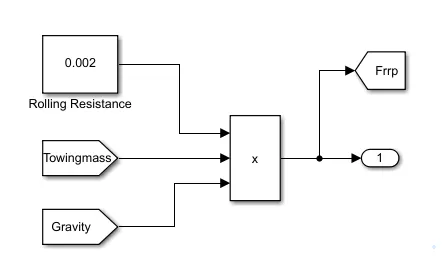
Rolling Resistance Force of Towing subsystem:
Aerodynamic Force subsystem:
Uphill Force subsystem:
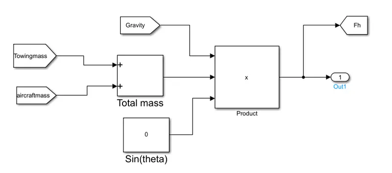
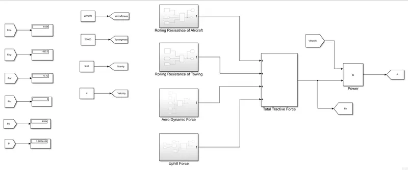
- By use of the different Simulink blocks we have created a power and force calculation model of the above calculate values.
Results of Simulink:
Excel sheet calculations link: https://docs.google.com/spreadsheets/d/11bZRV7OA0BQiqX2F4DEJRYRLxK-1Bdqf/edit?usp=sharing&ouid=103079569181236821437&rtpof=true&sd=true
Simulink model link: https://drive.google.com/file/d/1RsHUDre734mkHA-Dc5ZLkxfhrHGdi1FQ/view?usp=sharing
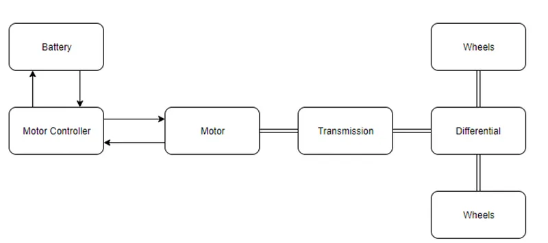
7) A. To design an electric powertrain with type of motor, it’s power rating, and energy requirement to fulfill aircraft towing application in Simulink. Estimate the duty cycle range to control the aircraft speed from zero to highest by Making all required assumptions and prepare a table of assumed parameters by also drawing a block diagram of powertrain.
B. To design above the parameters in excel sheet.
Estimation of duty cycle:
- Based on the calculations made in the 6(A) we require a Power of 19.82kW to the towing vehicle to tow the aircraft.
- Motor considered for drive train is Siemens 1LE7 IE2
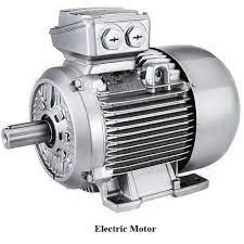
- Voltage : 230-440V, Working speed: 1500 rpm, Continuous/Peak power: 0.34kW/25kW.
- Considering 22kW as continuous power, the voltage is 400V.
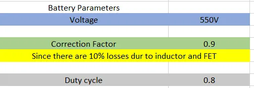
- Battery voltage to be considered as 550V.
- Duty cycle is given as Vo/Vb.
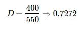
- Due to losses in the inductor and FET we need to consider 10% extra voltage to compensate.

- So the voltage demand from battery should be around 440V.
Assumed parameters for the model:
| Mass of the aircraft | 227000kgs |
| Mass of the pushback truck | 25000kgs |
| Rolling resistance coefficent | 0.002 |
| Drag coefficient | 0.03 |
| Air density | 1.125kg/m^3 |
| Frontal Area | 150m^2 |
| Uphill Gradient | 0 |
| Velocity | 4m/s |
| Battery Voltage | 550V |
| Loss due to inductor and FET | 10% |
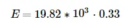
| Time for which vheicle towed | 20min = 0.33hr |
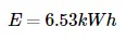
Energy of the Towing vehicle 
Block diagram of the powertrain:
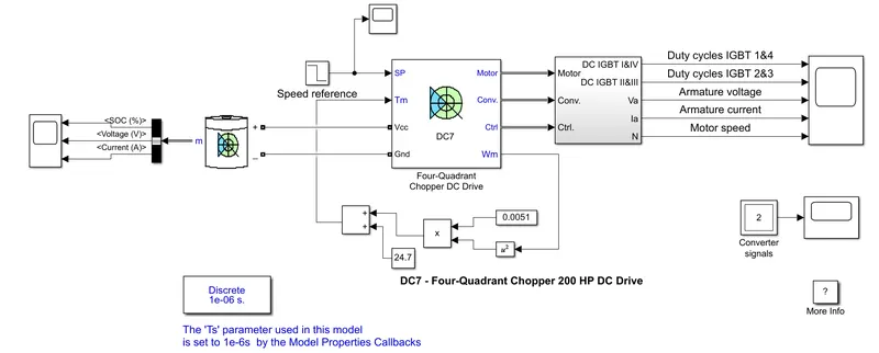
Simulink model:
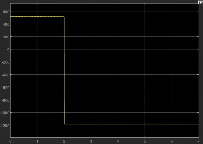
Input singal:
Output Signals:
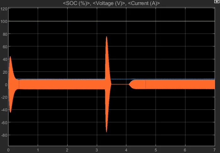
- Open DC7 block before starting change the initial bus voltage value to 515V.
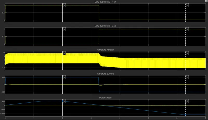
- When we run the model we can see that motor armature and voltage and current, four IGBt pulses, and motor speed in scope.
- The motor is coupled with other linear loads whcih means mechanical torque of load is proportional to speed.
- The speed reference is set at 500rpm at t=0sec. Observed that motor speed follows the reference and reaches steady state at 1.3sec.
- At t=2sec speed reference starts to drop to -1184rpm. The current reference decreses as reducethe elctromagnet torque. This cause the motor to decelrate with load torque.
- At t=2.2 sec the current reverses to produce a breaking electromagnetic torque Thid causes the DC bus voltage to increase.
- At t=3.35sec , the motor reaches 0 rpm and load torque negative.
- The negative current now produces accelerating electromagnetic torque to allow the motor to follow the negative speed.
- At t=6.3sec, the speed reaches to -1184rpm and stabilizes at reference.
b) Parameters in Excel sheet:
Google drive: https://drive.google.com/drive/folders/1hN41pvvMYq2Rewmqa4FXICCOgVw_EGcm?usp=sharing
Conclusions:
- Hence searched and listed out the total weight of various types of aircrafts.
- Studied about the ground speed and air speed and diffrence is that due to wind speed they bothe vary.
- Hence studied that running the aircraft by engine in airport will may lead to damage of engine and personnal working around their.
- Hence we stuidied about taxiing and towing which are the two methods by which aircraft can move on road.
- Hence studied about the take off power, tyre design, rolling resistance, tyre pressure, brake forces when landing.
- A. With necessary assumptions to we have calculated the force and power required to push / pull an aircraft by a towing vehicle.
B. Hence developed a Simulink model for above calculations.
- A. Hence designed an electric powertrain with motor typw, power rating, and energy requirement to fulfill aircraft towing application in Simulink and estimated the duty cycle range to control the aircraft speed from zero to highest and prepared a table of assumed parameters by also drawing a block diagram of powertrain.
B. Hence designed the parameters in excel sheet for above assumptions.