Week-6 Challenge: EV Drivetrain
1) Aim: To understand the types of power electronic circuits used in the electric and hybrid electric vehicles.
|
|
|
|
|
|
Conclusion: Hence the different types of power convereters circuits employed in the Electric and Hybrid electric vehicle are discussed.
2) Aim: To calculate the steady state speed of the Electric vehicle for the given input conditions.
Input conditions:
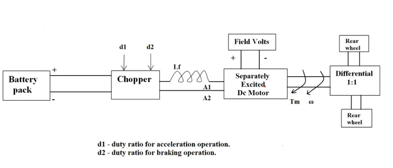
Battery pack volatge = 72V
Rated armature voltage = 72V
Rated armature current = 400A
Ra= 0.5Ω, KΦ= 0.7 Volt second
Chopper Switching frequency= 400 Hz
 => Vehicle speed-torque characteristics are given. => (1)
Duty ratio = 70%
Operating Volatge Vt = 72*0.7 = 50.4V
Speed-Torque characteristics of Motor:
ω = (Vt/KΦ) – (Ra/KΦ^2)*T
Tm = (Vt*KΦ/Ra) - (KΦ^2/Ra)*ω
Tm = (50.4*0.7/0.5) - (0.7^2/0.5)*ω
Tm = 70.56 - 0.98ω => (2)
%Calculate steady state speed of the vehcile
clear
close all
clc

%Inputs given
Vrated = 72; %rated armature voltage
Vt = 72*0.7;
Irated = 400; %rated armature current
k = 0.7; %motor constant
Ra = 0.5; %armature resistance
f = 400; %in Hz - switching Frequency
w = linspace(1,100,100);

% vehicle speed-torque characteristics
Tv = 24.7 + 0.0051.*w.^2;

% motor speed-torque characteristics
%Tm = (Vt*k/Ra) - (k^2/Ra)*w
Tm = 70.56 - 0.98.*w;

plot(w,Tv,'color','r');
hold on
plot(w,Tm,'color','b');
xlabel('Speed(rad/sec)');
ylabel('Torque(Nm)');
title('steady state speed of vehicle');
legend('vehicle Speed-Torque','motor Speed-Torque');
grid on 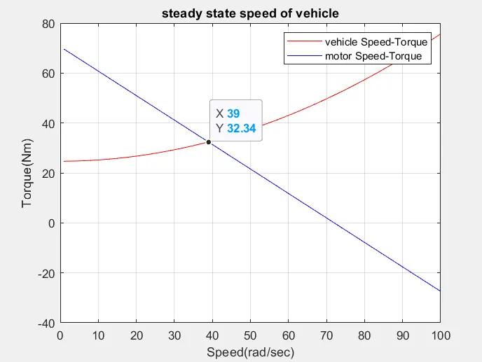
Conlusion: Hence the steady state speed of the vehicle is 39rad/s.
3) Aim: To develop a mathematical model of the DC Motor for the equation using Simulink
ω = (Vt/KΦ) – (Ra/KΦ^2)*T
Tm = (Vt*KΦ/Ra) - (KΦ^2/Ra)*ω
Mathematical Model:
Procedure:
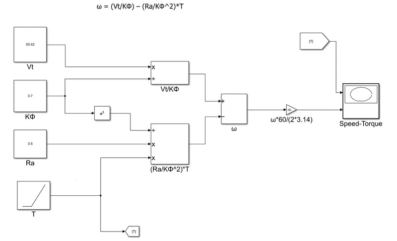
- The mathematical model of the DC motor equation ω = (Vt/KΦ) – (Ra/KΦ^2)*T.
- In this Ra is constant which are pre-defined while construction.
- The motor constant and voltage are also constants blocks for the motor input.
- The terminal voltage block is divided by motor constant block.
- The square block is added in order to obtain the square of the motor cnstant.
- A ramp block signal is selected as a torque to the motor.
- The Ra is multiplied with Torque and divided with square of motor constant.
- We get the speed of the vehicle in rad/sec in order to convert to rpm have a gain block of parameter 60/(2*3.14).
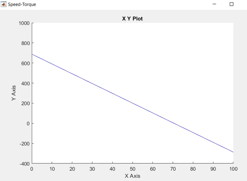
- The XY scope block is used in order to view the speed torque charcteristics.
- The X-axis is connected to the Torque and Y-axis is connected to the Speed.
- As per the question the values have be taken Vt = 50.4V, KΦ = 0.7, Ra = 0.5ohms.
Conclusion: Hence the mathematicla model of the DC Motor Characteristic equation ω = (Vt/KΦ) – (Ra/KΦ^2)*T is model using the Simulink and the outputs are plotted.
4) Aim: To refer the "INDUCTION VERSUS DC BRUSHLESS MOTORS BY WALLY RIPPEL, TESLA" blog and briefly explain the author's prespective.
- is a long-time proponent of electric vehicles. Prior to joining Tesla Motors, he was an engineer at Aero Vironment, where he helped develop the EV1 for General Motors and was featured in the documentary movie, Who Kiddel Eletcric Car? Wally has also worked for the Jet Propulsion Laboratory on electric vehicle battery research, among other projects. In 1968, as a Caltech undergraduate student, he built an electric car (a converted 1958 Volkswagen microbus) and won the Great Transcontinnetal Car Race against MIT.
- Way back there were lead acid batteries, DC brush motors, and contactor controllers. Today, none of these remain (including my hair). Lead has been replaced by Lithium and DC by either DC Brushless or Induction. Contactors, meanwhile, have given way to modulating inverters. However, is that we will see both induction and brushless machines “duke it out” for many years to come. Each will have its loyal proponents and religious detractors.
Brushless DC Motor & Drive:
- Rotor has two or more permanent magnets that will produdce the magnetic field.
- The generated magnetic field will go to the stator core and interacts with the current flowing in the stator windings to produce the inetraction between the stator and rotor.
- The torque produced will rotate the rotor and while rotating it is necessary that magnitude and polarity of stator currents should be continuoulsy varied in order to maintain the Power conversion efficiency.
- This should be provided by current control device known as "INVERTER".
- Brushless DC motor cannot produce starting Torque when directly connected to fixed frequency utility power. They need the aid of an inverter whose “phase” is maintained in step with the angular position of the rotor.
- Less rotor heat is generated with the DC brushless drive. Rotor cooling is easier and peak point efficiency is generally higher for this drive.
- The drive can operate at Unity power factor. So, Peak point energy efficiency for a DC brushless drive will be higher than Induction motor drive.
- In an ideal brushless drive, the strength of the magnetic field is produced by the adjusment of permanent magnets.
- DC brushless drives require an absolute position sensor.
- For maximum torque, especially at low speeds, the magnetic field strength (B) should be maximum – so that inverter and motor currents are maintained at their lowest possible values, that minimises the I² R losses and thereby optimizing efficiency.
- For low torque levels, the B field should be reduced such that eddy current and hystersis losses due to B are also reduced. So, B should be adjusted such that the sum of the eddy, hysteresis, and I² losses is minimized. Unfortunately, there is no easy way of changing B with permanent magnets.
- Permanent magnets are expensive – something like $50 per kilogram. Permanent magnet (PM) rotors are also difficult to handle due to very large forces that come into play when anything ferromagnetic gets close to them.
- DC brushless drives will likely continue to dominate in the hybrid and coming plug-in hybrid markets.
Induction Motor and Drives:
- The induction rotor has no magnets – but has stacked steel laminations with buried peripheral conductors that form a “shorted structure.”
- Currents flowing in the stator windings produce a rotating magnetic field that enters the rotor. In turn, the frequency of this magnetic field of rotor is equal to the difference between the applied electrical frequency and the rotational frequency of the rotor itself.
- Accordingly, an induced voltage exists across the shorted structure that is proportionate to this speed difference between the rotor and electrical frequency.
- As a result voltage, currents are produced within the rotor conductors that are approximately proportionate to the voltage, which in turn proportional to the speed difference.
- These currents interact with the original magnetic field to produce forces – a component of which is the desired rotor torque.
- When a 3-phase induction motor is connected to utility type 3-phase power, torque is produced at the outset and motor has the ability to start under load. No inverter is needed.
- While 3-phase induction motors have great utility, but cannot operate from DC; AC is a must. Also have limited starting torque and limited running peak torque capabilities, when compared to DC type machines.
- Add an inverter without any feedback control which can be operated on battery or other DC source; variable speed also becomes simple by adjusting the inverter frequency and torque performance is low compared with DC machines.
- Add some feedback loops such that the inverter produces the exact frequency that the motor desires and the induction motor is now capable of competing with DC and DC brushless for vehicle applications.
- induction drives require only a speed sensor.
- Induction machines have no magnets and B fields are adjustable, since B is proportionate to V/f.
- At light loads the inverter can reduce voltage such that magnetic losses are reduced and efficiency is maximized. Thus, the induction machine when operated with a smart inverter has an advantage over a DC brushless machine – magnetic and conduction losses can be traded such that efficiency is optimized.
- Induction drives may be the favored approach where high-performance is desired; peak efficiency will be a little less than with DC brushless, but average efficiency may be better.
- Induction motors will likely retain a cost advantage over PM machines. Due to the field weakening capabilities of induction machines, inverter ratings and costs appear to be lower, especially for high performance drives. Since spinning induction machines produce little or no voltage when de-excited, they are easier to protect.
- Induction machines are more difficult to control. Achieving stability over the entire torque-speed range and over temperature is more difficult with induction than with DC brushless. This means added development costs, but likely little or no recurring costs.
Conclusion:
- DC brushless drives will likely continue to dominate in the hybrid and coming plug-in hybrid markets.
- Induction drives will likely maintain dominance for the high-performance pure electrics.
- Induction and DC brushless live and work side by side during the coming golden era of hybrid and electric vehicles.