Week - 4
1) Aim: To implement the control logic of a washing machine using state flow as per given inputs.
Input conditions:
- If power supply available, system gets activated.
- if water supply not available, stop the process and indicate LED.
- Time for Soaking is 200sec, Washing time of 100sec
- Rinsing timeof 20sec then 50sec for Drying and finally after all process TURN ON the finish LED.
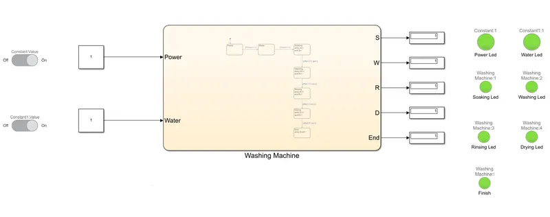
Model:
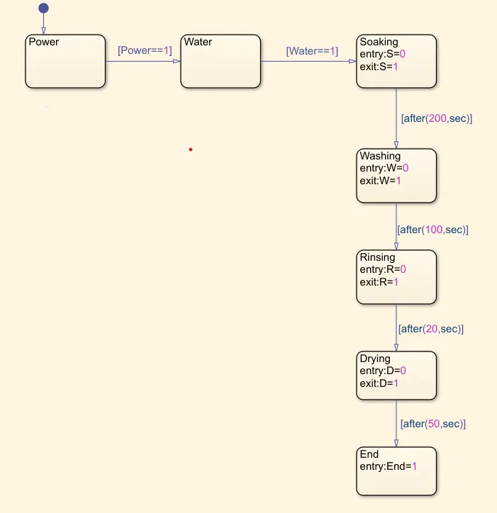
Stateflow:
Procedure:
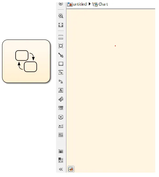
- The Stateflow is created by Chart block created where the conditions are given according to our inputs. The chart block will open up a different block other than the simulink block.
- The Stateflow is created as per the given input conditions as power supply ,water supply, soaking, washing, rinsing,drying and finish.The LED ON and OFF conditions is controlled by these conditions.
- The LED's are connected to the respective output display so that the LED glows whenever output gives high.
- The Soaking enters when S has value of 0 and exits when S has value of 1.
- Similarly all the other conditioins are created. Now the inputs and outputs should be mentioned for the chart configuration from symbols pane.
- Now the Lamp block is connected to the output of the S to sense and give the glow of LED.
- Similarly for the other blocks connected to their respective Led's.
- The inputs are given through the Power and Water to the chart block.
- The inputs are given through a switch controlled by the constant block and connected to each other.
- The diplays blocks are connected in order to connected the outputs of the chart block to the lamp led's.
- Now run the model for atleast 400sec (since we have 200sec of soaking, 100sec of washing, 20sec of rinsing and 50sec of drying = 370sec total) and for each block we have some delay to execute. In this case we have kept our delay as 5sec.
- To view the intermediate stages after runnig the model click on step forward so the intemdiate stages can be viewed as shown below in outputs.
Different stages of output:
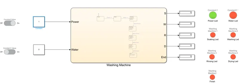
- The input condition when both power supply and water supply are OFF.
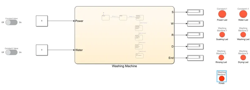
- When the Power supply is ON and Water supply is OFF.
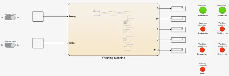
- When the Power supply ON and Water supply is ON.
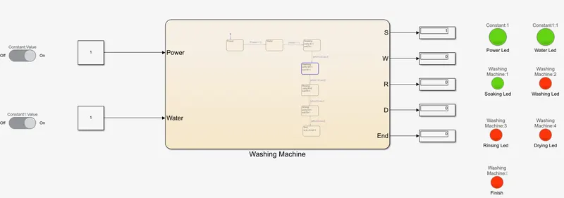
- The system condition after the prcoess of Soaking after 200sec.
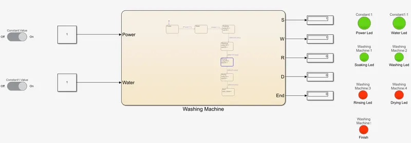
- System condition after the Washing process of 100sec.
- The Led's of the system after 20sec of Rinsing.
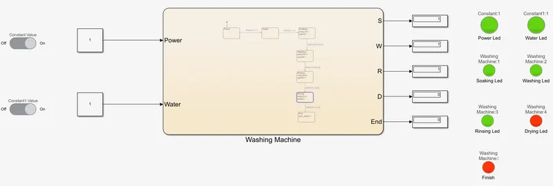
- The final section after the 50sec of drying and finish Led's.
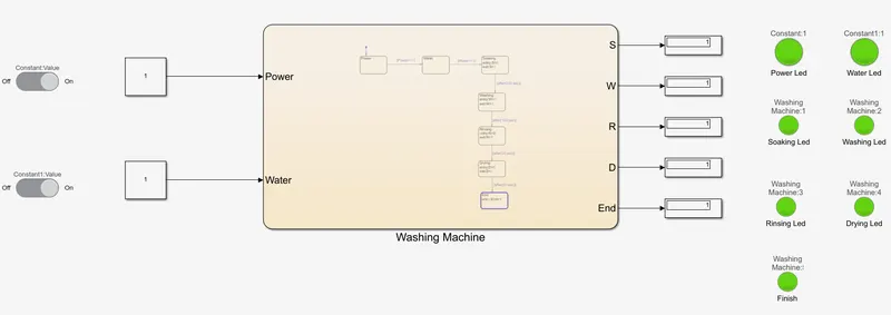
Conclusion:
Hence the implementation of the Washing machine using the stateflow is created, operated according to the inputs and
all the outputs are viewed.
2) Aim: To implement the simulink chart of "Gear shift" logic as per input conditions and also varing the input in running
and displaying the gear number according to the speed.
Input conditions:
| Speed Range(kmph) | Gear |
| 0-15 | 1 |
| 16-25 | 2 |
| 26-40 | 3 |
| 41-60 | 4 |
| Above 60 | 5 |
Model:
Stateflow Chart:
Procedure:
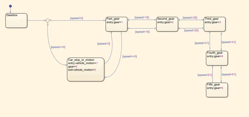
- The gear system block is created in order to vary the gears according to the speed variations.
- So when the speed is between 0-15kmph then the system should be in gear1. If the speed is zero then the gear shifts to zero and vehicle comes to stop.
- When the speed is 16-25kmph then system should be in gear2, 26-40kmph gear3 , 41-60kmph gear4 and for speeds above 60kmph the gear will be gear5.
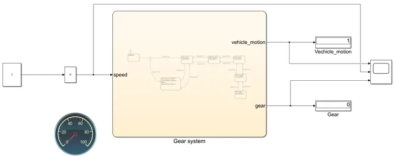
- Now a input is created by the slider gain by which we can create a real time simulation varying the inputs in real time.
- A constant block is connected to the slider gain block with a gain of 1.
- The chart block is created input as speed and output as vehicle motion and gear from the symbols panel.
- The output is given to the display blocks one display block is to shown the vehicle motion i.e., when output is 0 vehicle is in motion and if the output is 1 then vehicle is in rest.
- Another output display is given to the view the state of the gear.
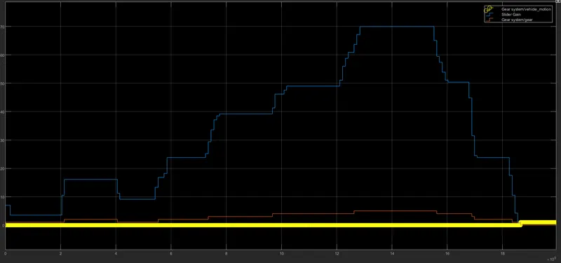
- All the graphs are view through the scope block.
- A circular gauge block is created and connected to the input variation to view the speed variation.
- Now run the system for infinte time and run the input speed in real time and view the output according to the input.
Outputs:
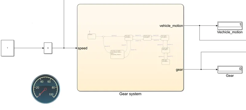
When the speed is 0kmph and its gear and vehicle motion.
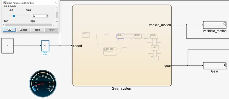
When the speed is 12kmph and view the gear.
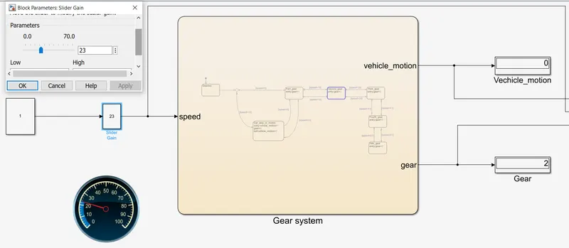
When the speed is 23kmph and view the gear.
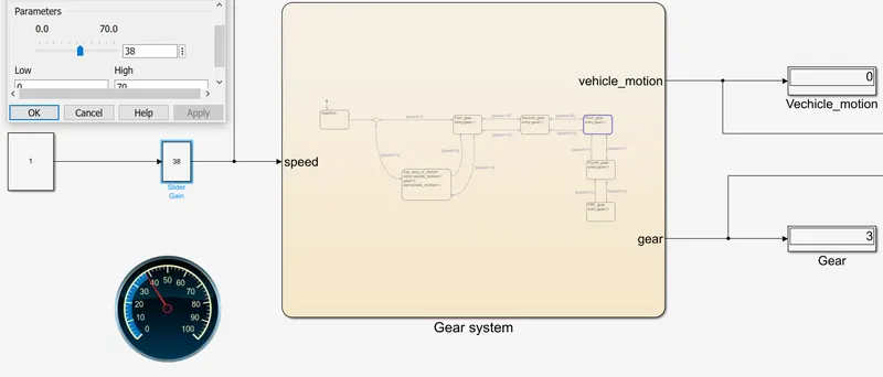
When the speed is 38kmph and view the gear.
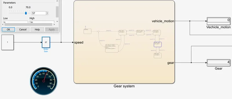
When the speed is 57kmph and view the gear.
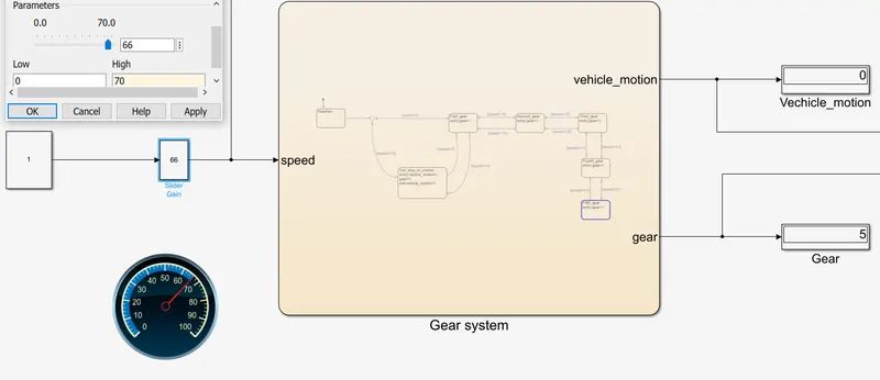
When the speed is 66kmph and view the gear.
Variation of input speed, vehicle motion and gear in the scope block.
Conclusion:
Hence the simulation chart for the "Gear shift" logic as per input conditions by varying the inputs in the real time and
displaying the gear number.