Week -2
1) Aim: To make a simulink model of doorbell using a solenoid when the switch is closed for 2 seconds ans observering
the results from the graph.
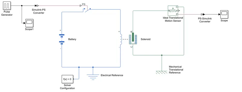
Model:
Procedure:
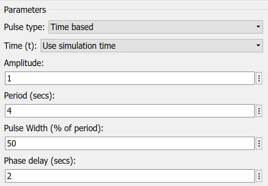
- The pulse generator block is used to generate the pulse since we need switch to be closed for 2 seconds so pulse is set to on for 2 seconds.
- Now we need to connect a switch block by which we need to control the parameters of the solenoid. Since switch is a simscape model we need to convert the input signal by connecting with a Simulink-PS converter block. The input signal is connected to physical signal port of the switch.
- The threshold value of the input signal is set 1 and the threshold value of the switch is set to 0.8. Whenever the input is greater than 0.8 the switch will be operated.
- A battery block is given to the switch to operate and the pulse generator block is used for the condition to get the switch closed.
- Now the switch block is connected to the solenoid whcih converts the electrical input to the mechanical work as output.
- To view the change in the mechanical postion of the piston of the soleniod we connect a ideal translational motion sensor block.
- The P port the sensor block is singnal so we need to convert this into simulink model we use a PS-Simulink converter block.
- Now to view the change in the position we connet the scope block to view graph.
- All the references are given to their respective blocks(i.e., electrical refernce to electrical block and mechanical reference to mechanical block).
- Connect a solver configuration so that it solve all the equtions in the background.
- Now run the system to view the change in the ouput when the pulse generated is above the threshold of the switch.
Pulse genterated input:
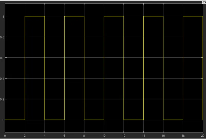
- In this we have run the simulation for 20sec with 2 seconds for every period.
Ouput:
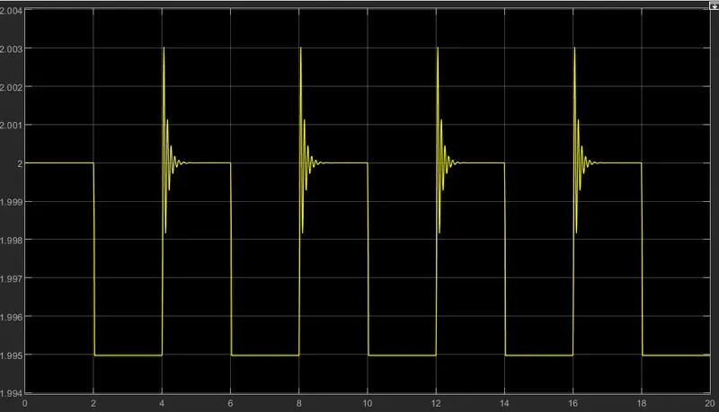
- In the ouput we have a value of high till 2 when the switch is open (i.e., when there is no input the solenoid dones't have any effect R will be away from the C of solenoid).
- When the switch gets closed the R of the solenoid moves towards C as shown in graph (2 to 1.995) at the end of the we can see a spike in the output which shows the dampnig of the signal.
Conclusion:
The simulation model of the doorbell using a solenoid is created and the output is verified.
2) Aim: To turn on or off the fan by sensing the temperature of the thermistor as per below conditions:
Temperature source: 20°C from 0 to 10 seconds, 27°C from 10 to 30 seconds and 23°C from 30 to 50 seconds.
Fan on conditions: If temperature is above 25°C on the fan otherwise off the fan.
Model:
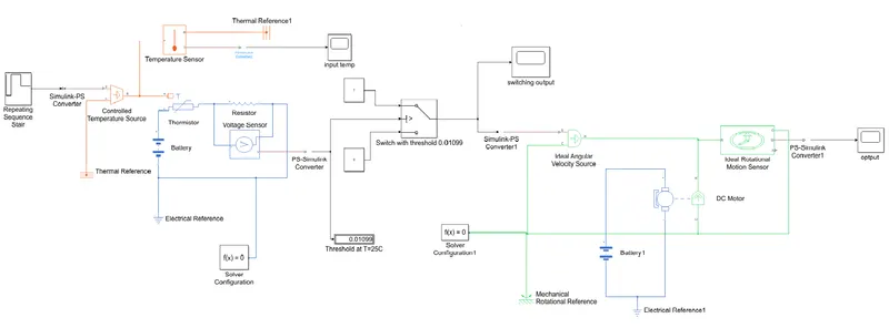
Procedure:
- A thermistor block which is supplied with battery for electrical input.
- The A terminal of the thermistor is connencted to the controlled temperature source block which gives the temperature input to the thermistor.
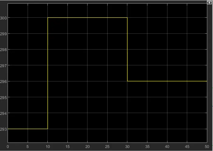
- The input values for the controlled temperature source is given through a repeating sequence stair block as input values of [293 300 300 296 296] with a time sample of 10 seconds through a "Simulink to PS converter" and this forms the input for the system.
- The input can be viewed through a temperature sensor connected from output of temperature source block to the A terminal of temparture sensor block and output of sensor is taken from T terminal and connected to the scope through "PS to Simulink converter" to view the input temperature graph.
- A resistor is connected in series with the thermistor in order to sense the heat flow and a voltage source is connected in parallel to the resistor to view the value of the voltage across the resistor.
- The Electrical reference block is connected to negative of battery and thermal refernce block given to the A terminal of the controlled temperature source block and to port B of thermal sensor block
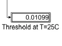
- The thermistor is set with a threshold value of 298K i.e., 25°C and based on that thresold temperature the heat in the thermistor is same in the resistor and the value of voltage across the resistor at the thresold temperature is taken to note.
- Now a switch is connected in order to control the variations in the fan. The output from the voltage source is connected to the control port of switch.
- The other two ports of the switch act as on and off situstions i.e., if the port 1 is satisfies the equation with control port then its treated as ON otherwise its OFF.
- Now we need to connect a DC motor in order to verify the rotaion of fan.
- Connect a ideal angular velocity source from the output of the switch, the input to the velocity source is given to port S through "Simulink to PS converter" the common is connected to the mechanical reference block.
- The output of the velocity source block is taken from the R and given to the R terminal of the DC motor.
- The motor is supllied with battery at the elctrical side and with velocity source at the mechanical side.
- Now another block ideal rotational montion sensor is connected to view the change in the DC motor ON and OFF.
- The output of the velocity source is connected to the input of the motion sensor to the R terminal.
- The output of the sensor is taken from the W terminal and given the scope through a coverter.
- Now all the common terminals of the velocity source, DC motor and motions sensor are connected to the mechanical reference and electrical reference to the battery.
- A solver configuartion block is connected in order to the equations under differnet conditions.
- Now run the program and calculate the value of the volatge sensor at condition of threshold of thermistor [298.15K].
- The value we got at the voltage sensor is given as condition to the switch condition as threshold value.
- Now again run the program and the output will be obtained.
Temperature Input:
Threshold value of switch:
Output:

- Hence from output we say that when Temp is 27°C from 10 to 30 seconds the fan gets ON and at the rest time its OFF as seen in graph.