Project-1: Powertrain for aircraft in runways
Project: Powertrain for aircraft in runways.
Aim: The following project has 2 parts:
Part A:
- Search and list out the total weight of various types of aircrafts.
- Is there any difference between ground speed and air speed?
- Why is it not recommended to use aircraft engine power to move it on the ground at Airport?
- How an aircraft is pushed to runway when its ready to take off?
- Learn about take off power, tyre design, rolling resistance, tyre pressure, brake forces when landing.
Part B:
- A. With necessary assumptions, calculate the force and power required to push / pull an aircraft by a towing vehicle.
- Develop the model for the calculated force and power using Simulink.
- A. Design an electric powertrain with type of motor, it’s power rating, and energy requirement to fulfill aircraft towing application in Simulink. Estimate the duty cycle range to control the aircraft speed from zero to highest. Make all required assumptions. Prepare a table of assumed parameters. Draw a block diagram of powertrain.
(Hint :DC7 Block)
- Also, Design the parameters in excel sheet.
Software Used: Simulink, MS Excel, MS Word.
Solution:
Part A:
- Search and list out the total weight of various types of aircrafts.
Types of Aircraft:
|
Commercial Airplanes |
Private Jets |
Private Propellor Planes |
|
|
|
|
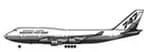
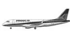
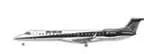
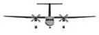 Passenger Turbo Props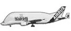
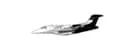
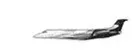
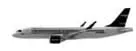
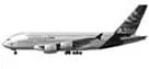
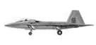
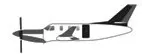
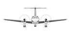
 Aerobatic
 Amphibious
 Military Turboprops
An aircraft's gross weight is limited by several weight restrictions in order to avoid overloading its structure or to avoid unacceptable performance or handling qualities while in operation.
Aircraft gross weight limits are established during an aircraft's design and certification period and are laid down in the aircraft's type certificate and manufacturer specification documents.
The absolute maximum weight capabilities of a given aircraft are referred to as the structural weight limits. The structural weight limits are based on aircraft maximum structural capability and define the envelope for the CG charts (both maximum weight and CG limits).
An aircraft's structural weight capability is typically a function of when the aircraft was manufactured, and in some cases, old aircraft can have their structural weight capability increased by structural modifications.
Maximum design taxi weight (MDTW)
The maximum design taxi weight (also known as the maximum design ramp weight (MDRW)) is the maximum weight certificated for aircraft manoeuvring on the ground (taxiing or towing) as limited by aircraft strength and airworthiness requirements.
Maximum design take-off weight (MDTOW)
Is the maximum certificated design weight when the brakes are released for take-off and is the greatest weight for which compliance with the relevant structural and engineering requirements has been demonstrated by the manufacturer.
Maximum design landing weight (MDLW)
The maximum certificated design weight at which the aircraft meets the appropriate landing certification requirements. It generally depends on the landing gear strength or the landing impact loads on certain parts of the wing structure.
MDLW must not exceed the MDTOW.
The MDL The maximum landing weight is typically designed for 10 feet per second (600 feet per minute) sink rate at touch down with no structural damage.
Maximum design zero-fuel weight (MDZFW)
The maximum certificated design weight of the aircraft less all usable fuel and other specified usable agents (engine injection fluid, and other consumable propulsion agents). It is the maximum weight permitted before usable fuel and other specified usable fluids are loaded in specified sections of the airplane. The MDZFW is limited by strength and airworthiness requirements. At this weight, the subsequent addition of fuel will not result in the aircraft design strength being exceeded. The weight difference between the MDTOW and the MDZFW may be utilised only for the addition of fuel.
Minimum flight weight (MFW)
Minimum certificated weight for flight as limited by aircraft strength and airworthiness requirements.
Types of Aircraft and its mass:
|
Aircraft |
Empty Weight |
Max Fuel Weight |
Max Cargo Weight |
Max Gross Take-off Weight |
Picture |
|
628,000 lbs |
661,400 lbs |
417,000 lbs |
1,411,000 lbs |
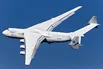 |
|
|
611,000 lbs |
560,000 lbs |
185,000 lbs |
1,268,000 lbs |
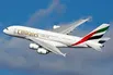 |
|
|
485,300 lbs |
427,400 lbs |
295,000 lbs |
987,000 lbs |
 |
|
|
370,000 lbs |
386,300 lbs |
119,000 lbs |
820,000 lbs |
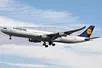 |
|
|
370,000 lbs 168,000 kg |
320,800 lbs 145,500 kg |
148,000 lbs |
776,000 lbs |
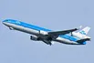 |
|
|
299,000 lbs 135,500 kg |
223,500 lbs |
126,300 lbs 57,300 kg |
560,000 lbs |
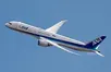 |
|
|
98,500 lbs |
53,100 lbs |
44,600 lbs |
187,000 lbs |
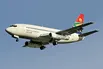 |
|
|
93,900 lbs |
48,700 lbs |
44,000 lbs |
150,000 lbs |
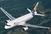 |
|
|
63,500 lbs |
28,600 lbs |
28,800 lbs |
106,000 lbs |
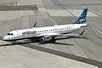 |
|
|
54,000 lbs 24,500 kg |
48,200 lbs 21,900 kg |
6,500 lbs |
100,000 lbs |
 |
|
|
48,160 lbs 21,850 kg |
19,600 lbs 8,900 kg |
6,075 lbs 2,760 kg |
80,500 lbs |
 |
|
|
39,300 lbs |
11,700 lbs |
18,700 lbs |
62,000 lbs |
 |
|
|
13,900 lbs 6,300 kg |
6,060 lbs |
2,900 lbs |
21,500 lbs |
 |
|
|
10,300 lbs 4,700 kg |
5,800 lbs |
2,200 lbs 1,000 kg |
17,200 lbs |
 |
|
|
7,100 lbs 3,200 kg |
3,200 lbs |
4,150 lbs |
12,000 lbs |
 |
|
|
3,200 lbs |
340 lbs |
1,250 lbs |
4,400 lbs |
 |
|
|
2,500 lbs 1,150 kg |
450 lbs |
850 lbs |
3,660 lbs |
 |
|
|
2,200 lbs |
520 lbs |
1,150 lbs |
3,600 lbs |
 |
|
|
2,250 lbs 1,000 kg |
485 lbs |
950 lbs |
3,600 lbs |
 |
|
|
1,700 lbs |
380 lbs |
560 lbs |
2,425 lbs |
 |
- Is there any difference between ground speed and air speed?
- Air speed: Air speed is the speed at which an aircraft is moving relative to the air it is flying in. As such, it’s also the speed at which the air is flowing around the aircraft’s wings.
- Ground speed: Ground speed is the aircraft’s speed relative to the ground. One thing that should be noted here is that it’s its horizontal rather than vertical speed – an aircraft climbing completely vertically would have a ground speed of zero.
If the aircraft is flying in the same direction as the wind is blowing, the aircraft experiences tailwind, and its ground speed is higher than its airspeed. On the other hand, if the wind is blowing against the direction the aircraft is traveling in, the aircraft experiences headwind, and its ground speed is lower than its airspeed.
If there is no wind at all, then both the aircraft’s airspeed and ground speed would be the same.
So,
Air Speed = Ground Speed – Wind Speed.
- Why is it not recommended to use aircraft engine power to move it on the ground at Airport?
As aircrafts doesn’t have a reverse gear, a pushback tug is used to move the aircraft backwards. For smaller aircraft, the pushback tug doesn’t require a massive amount of power. They utilize the weight of the tug, sometimes up to 60 tons, to ensure that the wheels don’t just spin on the tarmac.
Commercial airplanes are equipped with engines rated from 18,000 to nearly 100,000 lb of thrust. Such thrust levels provide for safe take-off, flight, and landing over a wide range of temperatures, altitudes, gross weights, and payload conditions. However, the exhaust wake from these engines can pose hazards in commercial airport environments. Operators and airport authorities must carefully consider these hazards and the resulting potential for injury to people and damage to or caused by baggage carts, service vehicles, airport infrastructure, and other airplanes.
- How an aircraft is pushed to runway when its ready to take off?
Commercial aircraft are pushed and pulled away from the terminal area to a position using pushback tugs where they can continue on using their engines. A commercial aircraft must be pushed backwards off the ramp, and onto a taxi way. Then the engines can start, the aircraft can proceed forward under its own power. A twin-engine jet might not start the second engine until it is close to take-off runway, clearance is certain.
- Learn about take off power, tyre design, rolling resistance, tyre pressure, brake forces when landing.
Take-off Power:
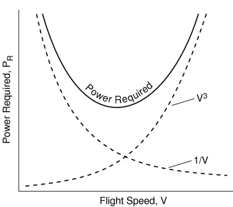
Typical power required curve for an aircraft
As seen in the above plot, an aircraft requires more power when it is in steady level flight position.
This is because at runway, the speed and take-off of the aircraft is totally dependent on the engine power because of the various forces acting on the aircraft (i.e., aircraft weight, aerodynamic resistance, ground resistance, etc.). When reaching the steady level, the wings and tail of the aircraft glides the aircraft through the air which reduces the required engine power of the aircraft.
On take-off, in order to position the aircraft to a safe height away from terrain and obstacles (i.e., a flight path of maximum height and minimum ground distance desired), the engine thrust is set to a high ‘take-off power’ setting and the aircraft attitude is pitched up to maintain a specific speed. Once the ‘safe height’ is reached the engine thrust can therefore be reduced to a more appropriate (i.e., efficient) setting and the aircraft flight path can be changed to a more appropriate (i.e., efficient) flight path.
Tyre Design:
Aircraft tires may be tube-type or tubeless. They support the weight of the aircraft while it is on the ground and provide the necessary traction for braking and stopping. The tires also help absorb the shock of landing and cushion the roughness of take-off, rollout, and taxi operations. Aircraft tires must be carefully maintained to perform as required. They accept a variety of static and dynamic stresses and must do so dependably in a wide range of operating conditions.
Types of Aircraft Tires:
A common classification of aircraft tires is by type as classified by the United States Tire and Rim Association. While there are nine types of tires, only Types I, III, VII, and VIII, also known as a Three-Part Nomenclature tire, are still in production.
Type I tires are manufactured, but their design is no longer active. They are used on fixed gear aircraft and are designated only by their nominal overall diameter in inches. These are smooth profile tires that are obsolete for use in the modern aviation fleet. They may be found on older aircraft.
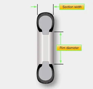
Type III tires are common general aviation tires. They are typically used on light aircraft with landing speeds of 160 miles per hour (mph) or less. Type III tires are relatively low-pressure tires that have small rim diameters when compared to the overall width of the tire. They are designed to cushion and provide flotation from a relatively large footprint. Type III tires are designated with a two number system. The first number is the nominal section width of the tire, and the second number is the diameter of the rim the tire is designed to mount upon.
 |
|
Type III tires |
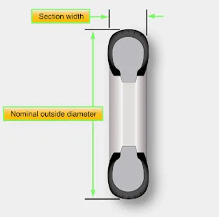
Type VII tires are high performance tires found on jet aircraft. They are inflated to high-pressure and have exceptional high load carrying capability. The section width of Type VII tires is typically narrower than Type III tires. Identification of Type VII aircraft tires involves a two-number system. An X is used between the two numbers. The first number designates the nominal overall diameter of the tire. The second number designates the section width. [Figure 2]
 |
|
Type VII tires |
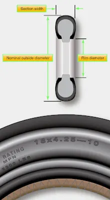
Type VIII aircraft tires are also known as three-part nomenclature tires. [Figure 3] They are inflated to very high-pressure and are used on high-performance jet aircraft. The typical Type VIII tire has relatively low profile and is capable of operating at very high speeds and very high loads. It is the most modern design of all tire types. The three-part nomenclature is a combination of Type III and Type VII nomenclature where the overall tire diameter, section width, and rim diameter are used to identify the tire. The X and “–” symbols are used in the same respective positions in the designator.
 |
Types VIII tires
Rolling Resistance:
Rolling resistance is the resistance offered by the ground to rolling of the wheel of the vehicle. For an aircraft, rolling resistance is mainly offered when the aircraft is moving on the runway for take-off and when moving after landing. The formula for rolling resistance is:
RR = μc *m*g,
Where,
μc = Coefficient of rolling resistance,
m = mass of aircraft,
g = gravitational acceleration.
If the mass of the aircraft is higher than usual, the aircraft might not reach the sufficient speed for take off due to higher rolling resistance offered by the ground due to higher aircraft mass, also for landing, if the mass of the aircraft is too low, the aircraft might not stop before the runway ends due to low value of rolling resistance offered by the ground due to lower aircraft mass.
Brake Forces when Landing:
We need to find the force required to stop the aircraft before the runway ends:
Suppose an aircraft – Boeing 747-10 is approaching the runway for landing with a speed of 170 MPH and the length of the runway is 3 Km and mass of the aircraft is 237 tons.
Here,
Landing Velocity(V) = 170 MPH = 76 m/s,
Runway length(l) = 3 Km = 3000m,
Aircraft mass(m) = 237 tons = 237000 Kg,
First, we need to find the required deceleration of the aircraft to stop before the runway ends which can be calculated using the formula below:
Deceleration(a) = V2/l,
a = 762/3000,
a = 1.925 m/s2.
Now, the required force can be calculated by,
Force(F) = m*a,
F = 237000 * 1.925,
Force required(F) = 456.3 kN.
Rolling resistance and Aerodynamic resistance also contributes to stop the aircraft after landing,
Rolling Resistance (RR) = μc *m*g,
Coefficient of RR(μc) of runway = 0.004,
RR = 0.004*237000*9.81,
RR = 9.3 kN.
Aerodynamic Resistance (AR) = ½*Cd*ρ*A*V2,
Where, Cd = Air drag coefficient for Boeing 747-10 = 0.031,
ρ = Air density at 250C = 1.168 kg/m3,
A = Frontal area of Boeing 747-10 = 40 m2(approx.).
AR = ½*0.031*1.168*40*762,
AR = 4.18 kN.
Braking Force required (BF) = F - RR - AR,
BF = 456.3 – 9.3 – 4.18,
BF = 442.82 kN.
Airplanes rely on a braking system to safely land on runways. At cruising altitude, most commercial airplanes fly at a speed of roughly 500 to 600 mph. When landing, however, they must reduce their speed. A typical 747, for instance, has a landing speed of about 160 to 170 mph. And upon touching the runway, airplanes must quickly brake until they come to a complete stop.
Wing Spoilers
Many airplanes use wing spoilers to assist with braking when landing. Not to be confused with ailerons, spoilers are extendable flaps on the ends of an airplane’s wings. Pilots can raise the spoilers to decelerate the airplane as it approaches the runway. And even while on the runway, pilots will typically leave the wing spoilers raised. Raised wing spoilers create drag, which essentially slows down the airplane so that it’s able to brake more quickly.
Disc Brakes
In addition to wing spoilers, airplanes use disc brakes. Airplane disc brakes are similar to the braking system in automobiles. They consist of a pair of callipers that, when engaged, squeeze pads against the rotors of an airplane’s landing gear.
Disc brakes are designed to remain static at all times. In other words, they don’t rotate with the wheels of an airplane’s landing gear. As the wheels turn, the disc brakes will remain static and stationary. They are a vital component of an airplane’s braking system because they are designed to apply pressure to the airplane’s wheels. Disc brakes will squeeze the wheels, thereby slowing down the speed at which they spin. In turn, this reduces the speed of the airplane so that it can come to a complete stop on the runway.
Reverse Thrust
Finally, many jet airplanes use reverse thrust to assist with braking during landings. Reverse thrust is a feature in jet engine airplanes that, as the name suggests, involves the reversal of the engines’ thrust. When flying, the thrust is projected out the rear of an airplane’s engines. When landing, however, pilots may use the reverse thrust feature. Reverse thrust changes the direction of the engines’ thrust. Rather than projecting out the rear, the thrust will be projected out the front. This reversal of thrust provides deceleration that allows airplanes to slow down more quickly when landing.
Part B:
- With necessary assumptions, calculate the force and power required to push / pull an aircraft by a towing vehicle.
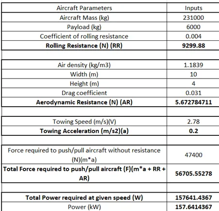
The force and power required to push / pull an aircraft by a towing vehicle is dependent on the mass of the aircraft, acceleration and the velocity of the aircraft when it is towed by the towing vehicle.
Rolling resistance (RR) also comes into play as it resists the push/pull of the aircraft, Aerodynamic resistance (AR) is almost negligible in this case as it is dependent on the value of velocity of the aircraft as it does not exceeds more than 10 kmph.
If m, a and V are the mass, acceleration and velocity of the aircraft, then:
Force to push/pull (F) = m*a + RR + AR,
Power to push/pull (P) = F*V.
Considering aircraft Boeing 747-10 is to be towed from its parking area with a velocity of 10 kmph and acceleration of 0.2m/s2 and having mass of 237 tons,
Aircraft mass (m) = 237 tons = 237000 Kg,
Towing speed (V) = 10 kmph = 2.78 m/s,
Acceleration (a) = 0.2 m/s2,
Force required to tow the aircraft without resistance = m*a = 237000*0.2 = 47.4 kN,
Rolling Resistance (RR) = μc *m*g,
Coefficient of RR(μc) of runway = 0.004,
RR = 0.004*237000*9.81,
RR = 9.3 kN.
Aerodynamic Resistance (AR) = ½*Cd*ρ*A*V2,
Where, Cd = Air drag coefficient for Boeing 747-10 = 0.031,
ρ = Air density at 250C = 1.168 kg/m3,
A = Frontal area of Boeing 747-10 = 40 m2(approx.).
AR = ½*0.031*1.168*40*2.782,
AR = 0.0056 kN.
Force required to tow the aircraft (F) = m*a + RR + AR,
F = 47.4 + 9.3 + 0.0056,
F = 56.71 kN.
Power required to tow the aircraft (P) = F*V = 56710*2.78 = 157.65 kW.
B. Develop the model for the calculated force and power using Simulink.
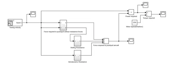
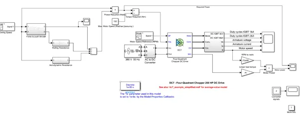
-The following Simulink model calculates the force, power and torque required (for motor rotating at 150 rad/sec) to push/pull aircraft Boeing 747-10:
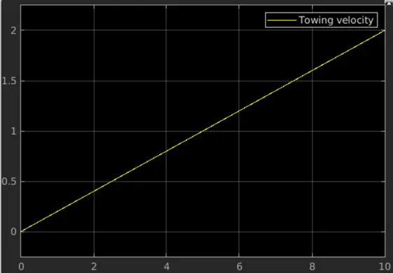
A signal builder block is used for towing speed input:
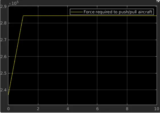
Plot for Force required to push/pull aircraft (N):
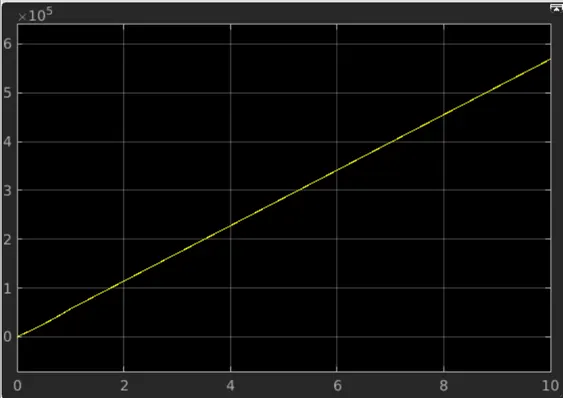
Power required to push/pull aircraft (Watts):
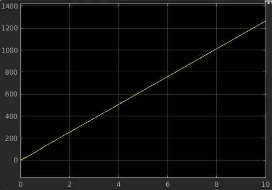
Torque required to push/pull aircraft for a motor with max speed of 150 rad/sec (Nm):
- A. Design an electric powertrain with type of motor, it’s power rating, and energy requirement to fulfill aircraft towing application in Simulink. Estimate the duty cycle range to control the aircraft speed from zero to highest. Make all required assumptions. Prepare a table of assumed parameters. Draw a block diagram of powertrain.
(Hint :DC7 Block)
The model used in Q.6b is used in DC7 model for load torque input:
Motor speed reference plot:
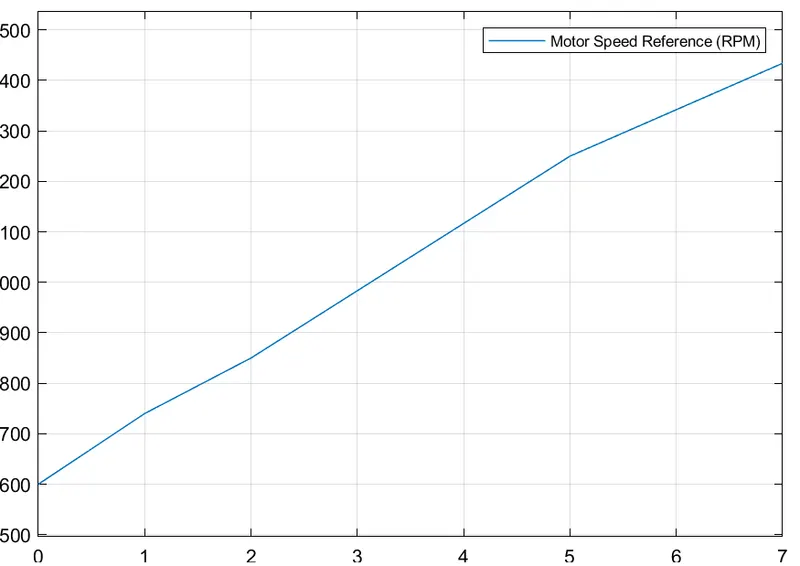
X-axis = Time (in seconds),
Y-axis = Speed (in RPM) (0-1434).
It plots the motor power and power required plots:
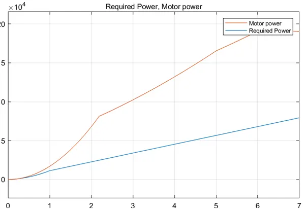
X-axis = Time (in seconds),
Y-axis = Power (in Watts) (0-200000).
B. Also, Design the parameters in excel sheet.