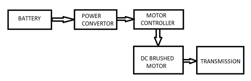
Project-1: Powertrain for aircraft in runways
PART A
Q1. Weight of various aircrafts are as follows:
| Aircraft | Weight (kg) |
| Airbus A380-800 | 575000 |
| Boeing 747-800 | 447700 |
| Airbus A340-500 | 372000 |
| Boeing 777-300ER | 352000 |
| Boeing 787-10 | 254000 |
| Boeing 737-900 | 85000 |
| Airbus A320-100 | 68000 |
| Gulfstream G650 | 45200 |
| Bombardier CRJ900 | 36500 |
| Cessna 206H | 1630 |
Q2.
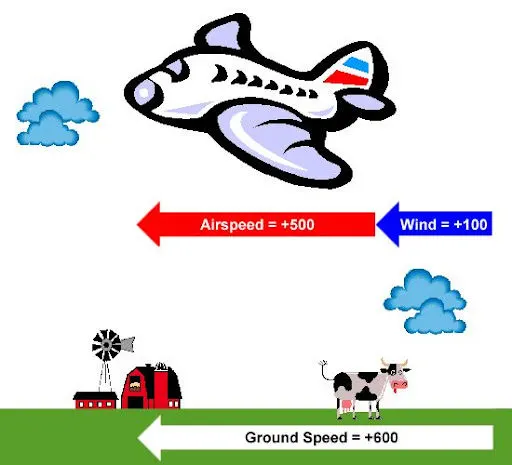
Wind Speed:
For a reference point picked on the ground, the air moves relative to the reference point at the wind speed. Notice that the wind speed is a vector quantity and has both a magnitude and a direction. Direction is important. A 20 mph wind from the west is different from a 20 mph wind from the east. The wind has components in all three primary directions (north-south, east-west, and up-down). In this figure, we are considering only velocities along the aircraft's flight path. A positive velocity is defined to be in the direction of the aircraft's motion. We are neglecting cross winds, which occur perpendicular to the flight path but parallel to the ground, and updrafts and downdrafts, which occur perpendicular to the ground.
Ground Speed:
For a reference point picked on the ground, the aircraft moves relative to the reference point at the ground speed. Ground speed is also a vector quantity so a comparison of the ground speed to the wind speed must be done according to rules for vector comparisons.
Airspeed:
The important quantity in the generation of lift is the relative velocity between the object and the air, which is called the airspeed. Airspeed cannot be directly measured from a ground position, but must be computed from the ground speed and the wind speed. Airspeed is the vector difference between the ground speed and the wind speed.
Airspeed = Ground Speed - Wind Speed
On a perfectly still day, the airspeed is equal to the ground speed. But if the wind is blowing in the same direction that the aircraft is moving, the airspeed will be less than the ground speed.
Q3.Why is it not recommended to use aircraft engine power to move it on the ground at Airport?
Commercial airplanes are equipped with engines rated from 18,000 to nearly 100,000 lb of thrust. Such thrust levels provide for safe takeoff, flight, and landing over a wide range of temperatures, altitudes, gross weights, and payload conditions. However, the exhaust wake from these engines can pose hazards in commercial airport environments. Operators and airport authorities must carefully consider these hazards and the resulting potential for injury to people and damage to or caused by baggage carts, service vehicles, airport infrastructure, and other airplanes.
Q4. How an aircraft is pushed to runway when its ready to take off?
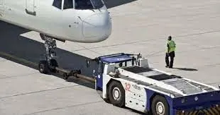
When the aircraft is eady to take off, a pushback truck reverses the aircraft into taxiing position, pushing it with a towbar attached to the nose-wheel strut. Or, in the most modern versions, by actually lifting the wheel. That speeds up coupling and decoupling.
Q5.Learn about take off power, tyre design, rolling resistance, tyre pressure, brake forces when landing.
Take Off Power:
Takeoff is the phase of flight in which an aerospace vehicle leaves the ground and becomes airborne.
For light aircraft, usually full power is used during takeoff. Large transport category (airliner) aircraft may use a reduced power for takeoff, where less than full power is applied in order to prolong engine life, reduce maintenance costs and reduce noise emissions. In some emergency cases, the power used can then be increased to increase the aircraft's performance. Before takeoff, the engines, particularly piston engines, are routinely run up at high power to check for engine-related problems.
Tyre Design:
When one considers the forces that aircraft tires endure, it seems amazing that engineers were ever able to develop these special products. Some tires are subjected to speeds as fast as a race car while at the same time supporting more weight than the largest land moving machines. They go through cyclic exposure to varying temperatures and pressures. These factors make aircraft tire design a critical process and tire maintenance an ever important step in safe aircraft operation.
Two types of tires are used in aircraft applications — bias-ply tires and radial tires. Although both types of tires share some similarities in design, there are differences that need to be noted.
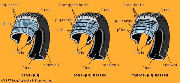
Bias-ply tire construction
Tread:
The tread is made of rubber mixed with other additives to obtain the desired level of toughness, durability, and resistance to wear. The tread pattern is designed to aircraft operational requirements, with the ribbed tread design used widely due to its good traction under varying runway conditions.
Sidewall:
The sidewall is a protective layer of rubber that covers the outer casing ply. It extends from the tread edge to the bead area.
Tread Reinforcing Ply:
One or more layers of fabric that strengthens and stabilizes the tread area for high-speed operation. It also serves as a reference for the buffing process when tires are retreaded.
Buff Line Cushion:
The buff line cushion is made of rubber compound to enhance the adhesion between the tread reinforcing ply and the breakers or casing plies. It is of sufficient thickness to allow for the removal of the old tread when the tire is retreaded.
Breakers:
Breakers are reinforcing plies of rubber-coated fabric placed under the buff line cushion to protect casing plies and strengthen and stabilize the tread area. They are considered an integral part of the casing construction.
Casing Plies:
Alternate layers of rubber-coated fabric (running at opposite angles to one another) provide the strength of the tire.
Wire Beads:
Hoops of high tensile strength steel wire that anchor the casing plies and provide a firm mounting surface on the wheel. The outer edge of the bead that fits against the wheel flange is called the bead heel. The inner bead edge is called the bead toe.
Apex Strip:
A wedge of rubber affixed to the top of the bead bundle.
Flippers:
Layers of rubberized fabric that help anchor the bead wires to the casing and improve the durability of the tire.
Ply Turnups:
The casing plies are anchored by wrapping them around the wire beads, thus forming the ply turnups.
Chafer:
A protective layer of rubber and/or fabric located between the casing plies and wheel to minimize chafing.
Liner:
In tubeless tires, the liner is a layer of low permeability rubber that acts as a built-in tube and restricts gas from diffusing into the casing plies. In tube-type tires, a thinner liner is used to prevent tube chafing against the inside ply.
Radial-ply tire construction
Overlay:
A layer of reinforcing rubber coated fabric placed on top of the belts to aid in high speed operation.
Belt Plies:
A composite structure that stiffens the tread area for increased landings. The belt plies increase the tire strength in the tread area.
Casing Plies:
As in bias-ply tires, the casing plies are layers of rubber-coated fabric. However, unlike those in bias plies that run at opposite angles to one another, radial plies run radially from bead to bead.
Chippers:
The chippers are layers of rubber-coated fabric applied at diagonal angles that improve the durability of the tire in the bead area.
Rolling Resistance:
Rolling resistance happens because the force pushing backwards against the tyre as it comes into contact with the road is bigger than the force pushing forwards as it leaves.
Tyre Pressure:
An aircraft tire or tyre is designed to withstand extremely heavy loads for short durations. The number of tires required for aircraft increases with the weight of the aircraft, as the weight of the airplane needs to be distributed more evenly. Aircraft tire tread patterns are designed to facilitate stability in high crosswind conditions, to channel water away to prevent hydroplaning, and for braking effect.Aircraft tires generally operate at high pressures, up to 200 psi (14 bar; 1,400 kPa) for airliners, and even higher for business jets. The main landing gear on the Concorde was typically inflated to 232 psi (16.0 bar), whilst its tail bumper gear tires were as high as 294 psi (20.3 bar).
Brake force on landing:
Stopping a 200-tonne aircraft landing at 180 mph requires a lot of braking force. To do this, the 787 has one brake unit on each of the eight wheels on the main gear assembly. On other aircraft types, the brake units are powered by the hydraulics system. An electrical signal is sent from the flight deck to hydraulic actuators near the main landing gear. Here, hydraulic fluid at 3,000 pound per square inch is used to force the brake unit against the wheel, thus slowing it down.
This system works fine, but the pipes and actuators that form this part of the hydraulic system come at a considerable weight cost. Extra weight means more fuel burn, which in turn increases costs and carbon emissions. What if the brakes could be powered a different way?
That’s the case on the 787 Dreamliner. Designers did away with the use of the hydraulic system and all its associated architecture and instead used electricity to power the brakes. When the pilots press on the brake pedals, an electrical signal is sent to the brake unit on the wheel. Here, electrically powered actuators are used to press the carbon brake disc against the wheel, slowing it down.
By changing to electric brakes, a 787-8 saves 141 pounds per aircraft and a 787-9 saves 245 pounds. The brakes are also known as “plug and play” because electrical wiring replaces the traditional hydraulics and it’s much easier and quicker to change the brake units when needed. Smart features also allow engineers to monitor the brake performance more closely, giving a real-time measurement of wear on the carbon disks.
Part B.
6. With necessary assumptions, calculate the force and power required to push / pull an aircraft by a towing vehicle.
The force required for push /pull can be calculated as follows:
`F=F_(rr)+F_(ad)` eq1
where `F_(rr)=mu_(rr)mg` is Rolling resistance eq2
and `F_(ad)=0.5rhoAC_dV^2` is the Aerodynamic drag eq3
Let us assume the different values as follows considering Boeing 747-100:
`mu_(rr)`=0.02
m=162400 kg
g=9.81m/s
A=L*W=70.6m*19.3m
`C_d`=0.03
V=20kmph=5.56m/s
`rho=1.225`kg/m
Putting the following values in equations 2 and 3 we get
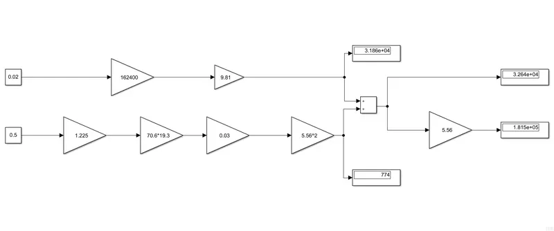
`F_(rr)=0.02*162400*9.81=31862.88N`
`_(ad)=0.5*1.225*70.6*19.3*0.03*5.56^2=733.99N`
`herefore total force for push/pull is approximately 32637N`
Power=F*V
= 32637*5.56
=181.46 KW
The simulink model of the same was developed as below and the results were matching.
---------------------------------------------------------------------------------------------------------------------------------
Q7.
From the previous calculation we know the power requirement which will be
Output power=181.46W
Considering it undergoes losses, and finding a suitable motor to meet the power requirement, I've selected Brushed DC electric motor (Z4-280-21)
It has the following specifications:
Rated Power=200kW
Rated Voltage= 440V
Rated Current= 498A
Now the Energy required by such a motor to run for 15min(0.25 Hr) would be as follows:
E= 200*0.25=50kWh
Now to calculate the duty cycle in order to get top speed,
D=`(P_o)/P_i`
=181.46/200=0.9073
So to change speed from 0 to top speed, We have to change the duty cycle from 0 to 0.9073
| Aircraft weight | 162400kg |
| Aircraft Length | 70.6m |
| Aircraft width | 19.3m |
| Co-eff of rolling friction | 0.02 |
| Co-eff of drag | 0.03 |
| Air pressure | 1.225kg/m |
| Motor Rated Power | 200kW |
| Motor Rated Voltage | 440V |
| Motor Rated Current | 498A |
| Motor Efficiency | 90.1% |