Project-1: Powertrain for aircraft in runways
Project-1: Powertrain for aircraft in runways
1.Search and list out the total weight of various types of aircraft.
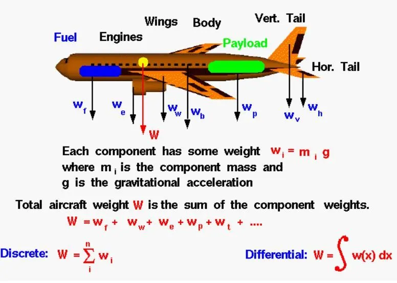
ANS: Aircraft gross weight is the total weight of any aircraft during ground or flight operations. The gross weight will decrease during the flight option as the jet fuel gets consumed. At the moment of releasing its brakes, the gross weight of an aircraft is equal to its takeoff weight. During the flight, an aircraft's gross weight is referred to as the en-route weight or in-flight weight.
Aircraft are mainly divided into aerostat and aerodyne.
The former is lighter than air and the latter is heavier than air.
1. AEROPLANES:
An airplane or airplane (informally plane) is a fixed-wing aircraft that is propelled forward by thrust from a jet engine, propeller, or rocket engine. Airplanes come in a variety of sizes, shapes, and wing configurations. The broad spectrum of uses for airplanes includes recreation, transportation of goods and people, military, and research.
a) Boeing 747
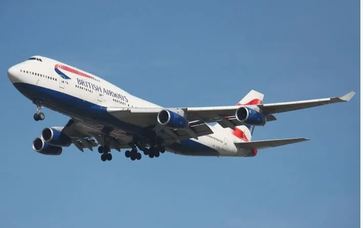
447,700 Kg
b) Antonov An-225 Mriya
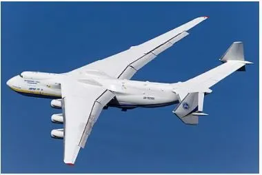
640,000 Kg
c)KLM Mc-Donnell Douglas MD-11
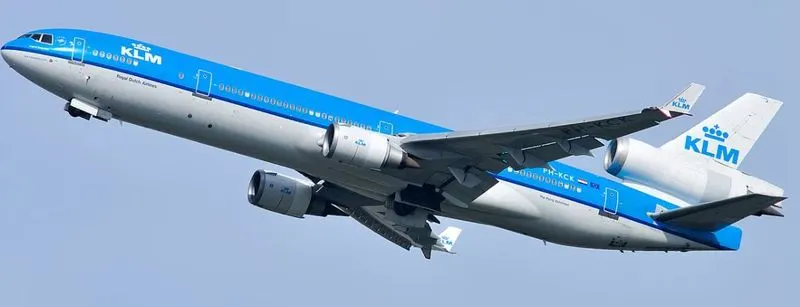
273,300 Kg
d) Bombardier Q400
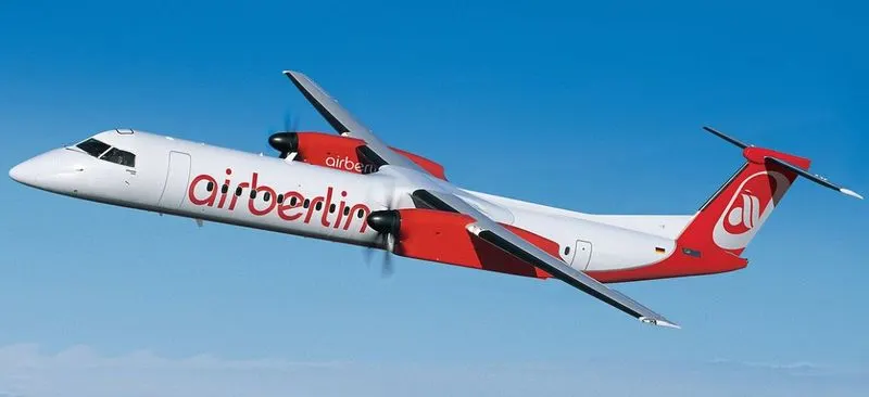
28,000 Kg
e) Embraer EMB-500 Phenom
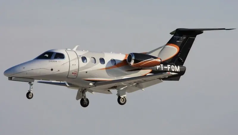
4800 kg
2.HELICOPTERS
A helicopter is a type of aircraft. It uses rotating, or spinning, wings called blades to fly. Rotating blades, or a rotor, let helicopters do things airplanes cannot.In order to fly, an object must have "lift." Lift is what pushes something up. Lift is made by wings. Wings have a curved shape on top and are flatter on the bottom. That shape makes airflow over the top faster than under the bottom. The faster air on top of the wing makes suction on the top of the wing and the wing moves up. Airplanes get lift from their wings. A helicopter's rotor blades are spinning wings. A helicopter moves air over its rotor by spinning the blades. The rotor makes the lift that carries the helicopter up.
a) Mil Mi- 12
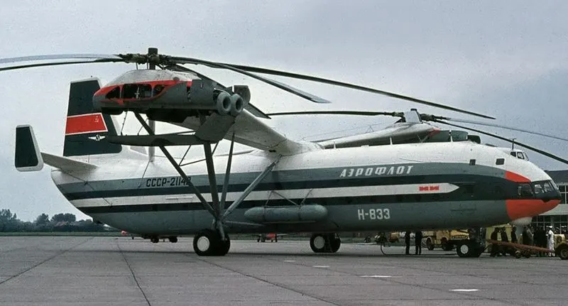
the largest helicopter ever built.
105000 kg
b) Sikorsky S-92
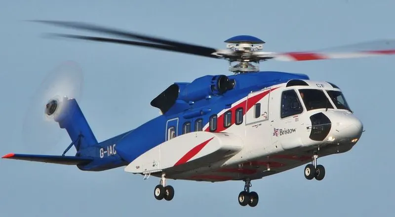
26500 Kg
c) AeroVelo Atlas

282 Kg
d) Bell 412
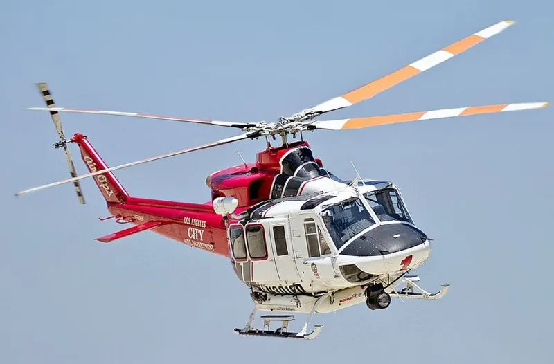
11900 Kg
3) Convertiplanes
a) Bell Boeing V-22 osprey
27445 kg
b) Augusta Westland AW609
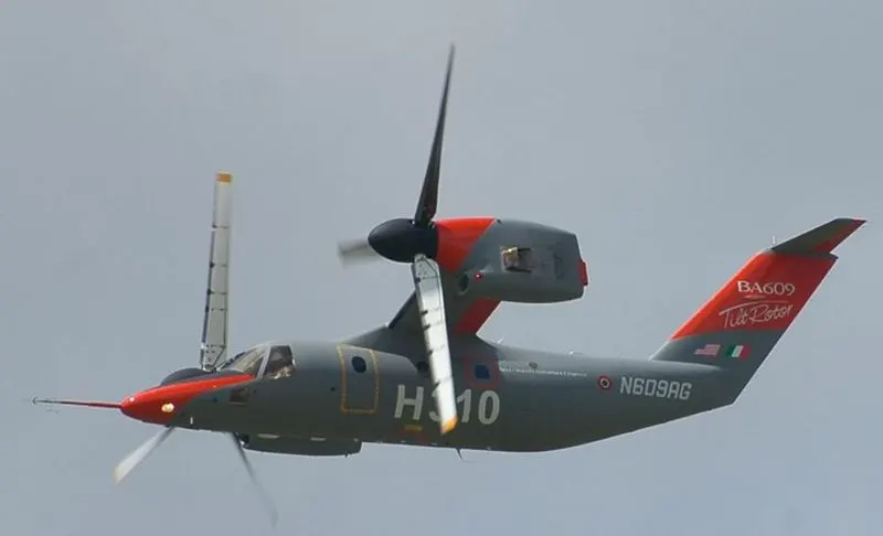
7600Kg
3) AIRSHIPS
airship, also called dirigible or dirigible balloon, a self-propelled lighter-than-air craft. Three main types of airships, or dirigibles (from French diriger, “to steer”), have been built: nonrigid (blimps), semigrids, and rigids. All three types have four principal parts: a cigar-shaped bag, or balloon, that is filled with a lighter-than-air gas; a car or gondola that is slung beneath the balloon and holds the crew and passengers; engines that drive propellers; and horizontal and vertical rudders to steer the craft.
a) Zepplin NT amk
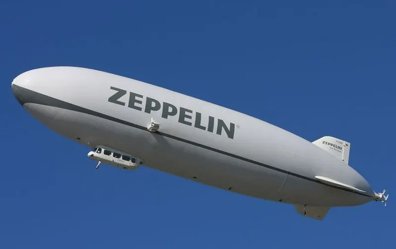
6622 kg
b) R 101
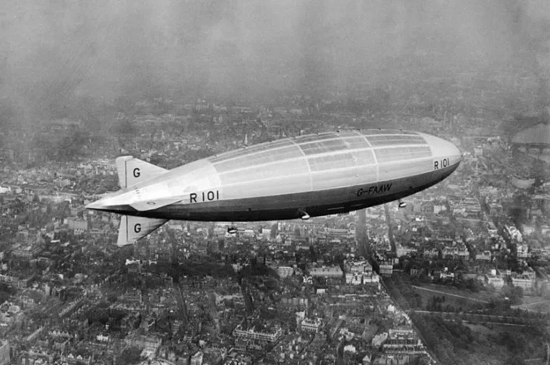
133229 kg
4) GLIDER
A glider or sailplane is a type of glider aircraft used in the leisure activity and sport of gliding (also called soaring). This unpowered aircraft can use naturally occurring currents of rising air in the atmosphere to gain altitude. Sailplanes are aerodynamically streamlined and so can fly a significant distance forward for a small decrease in altitude.
a)Arsenal Air 100
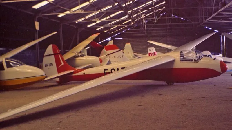
284 Kg
b) Schempp-Hirth Acrus
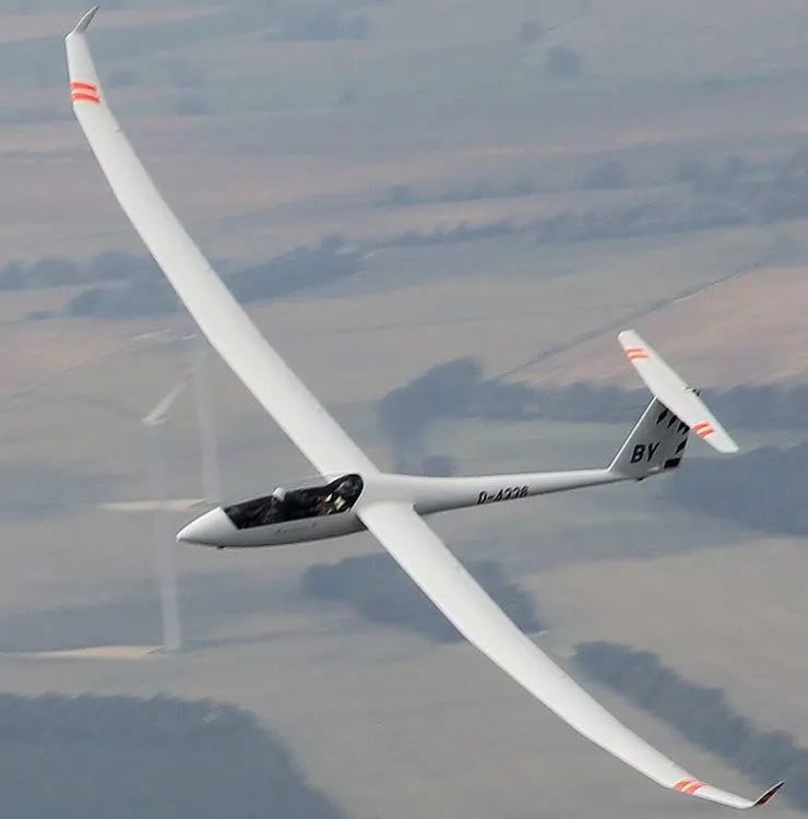
430 Kg
c)PH-1274 Rolladen Schneider
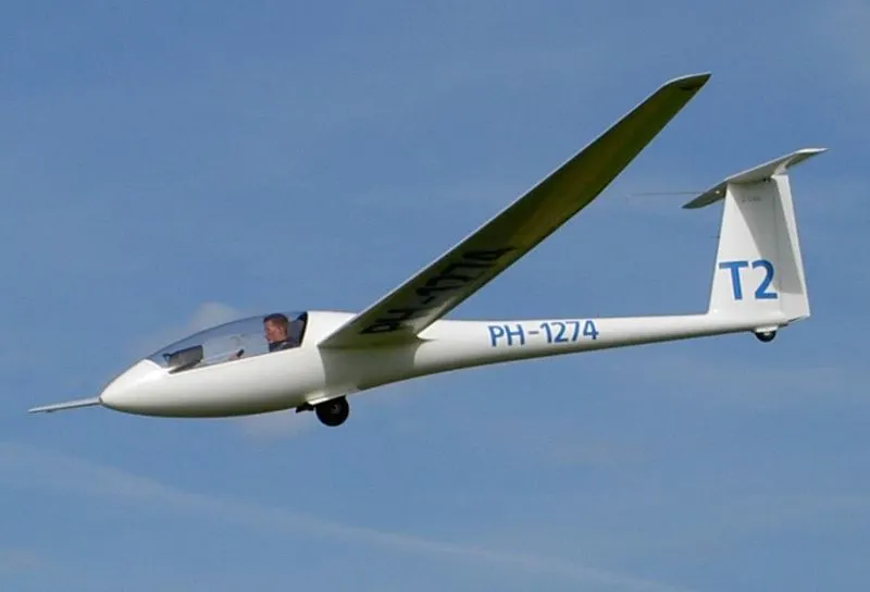
500 Kg
5)HOT AIR BALLOONS
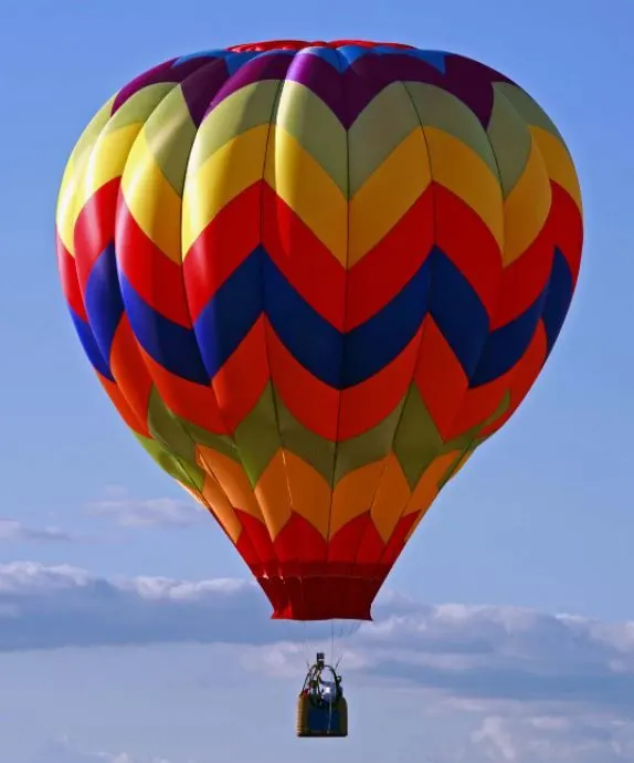
400 Kg
-------------------------------------------------------------------------------------------------------------------------------------------
2. Is there any difference between ground speed and airspeed?
ANS: There are mainly 5 kinds of speeds a pilot needs to measure:
- Indicated Air Speed
- True Air Speed
- Ground Speed
- Calibrated Air Speed
- Equivalent airspeed
TRUE AIRSPEED(TAS)
- It is the speed of the air relative to the air mass it is flying through.
- In still air, the true airspeed is the same as the ground speed.
- Consider if there is a headwind of 20 kts, the TAS will be 20 more than GS as the relative velocity increase. If there is a tailwind, TAS will be 20 less than the GS.
- True airspeed is calculated by taking the indicated airspeed and adjusting for pressure and temperature variables
- True airspeed is also impacted by altitude. At higher altitudes, with less dense air, the aerodynamic drag on the plane decreases, and the true airspeed increases. The rate of increase is 2% per thousand feet.
INDICATED AIRSPEED:
- Measure the speed of the airplane/aircraft as it moves through the air.
- It is the speed of the aircraft relative to the air mass it is flying through indicated by the pitot tube. Pitot tube measures airspeed using the pressure of the air. As the altitude increases, the pressure decreases.
- As the altitude increases, for a particular TAS, IAS would become lesser. This is because lesser air molecules will enter the pitot tube.
- In order to keep a constant IAS, TAS should be increased during the climb/take-off.
- This is the speed indicated on ASI.
- It is indicated in MPH or KNOTS
- Sometimes there can be errors caused due to instrument faults or the position of the pitot tube. This can lead to some inaccuracy in measurement.
- so we use the CAS.
CALIBRATED AIRSPEED:
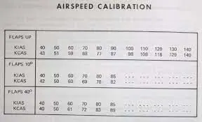
- Calibrated airspeed is the indicated airspeed corrected for errors.
- The manufacturer will publish a calibration table in the aircraft manual that will determine the CAS based on certain configurations and indicated airspeed.
EQUIVALENT AIRSPEED:
- Calibrated airspeed correct for compressibility error
- Compressibility errors occur when flying more than 300 knots.
- Since this calculation is complex, it is calculated using real-time avionics.
GROUND SPEED(GS)
- it is the speed of the airplane/aircraft moving over the ground.
- It has got nothing to do with any atmospheric conditions.
- used by pilots when making ground and distance calculations.
A device that is used to measure airspeed is the Airspeed Indicator(ASI). It is one of the 6 basic flight instruments. This is linked to the pitot-static system which means that its measurement depends on the air pressure.
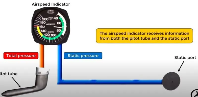
The pitot tube provides the total pressure and the static port provides the static pressure.
The airspeed indicator is a dynamic pressure gauge that is calibrated to indicate airspeed. Since dynamic pressure is proportional to speed, if the dynamic pressure is high, it would be interpreted as high speed and the ASI will give that value.
The diagram below shows the inside of the ASI
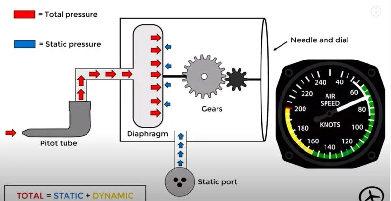
- TOTAL PRESSURE=STATIC PRESSURE + DYNAMIC PRESSURE
- The pitot tube is connected to a diaphragm. The tube measures total pressure. The static port is directly connected to the vessel. There is a needle that connects the gears(which indicates the air speed).
- The total pressure causes the diaphragm to expand but the static pressure opposes it. This gives us dynamic pressure.
- That pressure is exerted on the gear and it is indicated in meter.
SINCE THIS MEASUREMENT IS NOT COMPLETLY ACCURATE, WE USE THE PARAMETERS LIKE GS, TAS, IAS, and CAS
------------------------------------------------------------------------------------------------------------------------------------
3. Why is it not recommended to use aircraft engine power to move it on the ground at the Airport?
ANS: For movement on the ground the aircraft uses its own engines, however since the aircraft cannot move backward on its own, there are pushback trucks on the airport
A pushback truck lifts the front wheel of the aircraft, their role in most airports is to move the aircraft away from the parking spot onto the taxiways. Here the truck is removed and when all platform staff is out of the way the engines are started one by one. From here on the aircraft moves on its own power to the runway. In the aircraft, you will hear the engine spinning up when power is demanded acceleration.
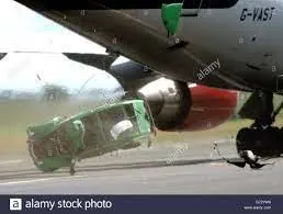
But it is not recommended to use the aircraft engine power to move on the ground. The exhaust wake(jet blasts) from these engines can pose hazards in commercial airport environments. Operators and airport authorities must carefully consider these hazards and the resulting potential for injury to people and damage to or caused by baggage carts, service vehicles, airport infrastructure, and other airplanes. It is recommended to maintain a safe distance of 400 feet.
Another reason engine power is not recommended is because the noise produced from it can cause permanent ear damage.
-------------------------------------------------------------------------------------------------------------------------------------------
4. How an aircraft is pushed to the runway when it is ready to take off?
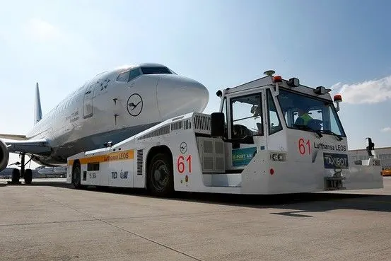
ANS: A so-called pushback truck reverses the aircraft into taxiing position, pushing it with a towbar attached to the nose-wheel strut. Or, in the most modern versions, by actually lifting the wheel. That speeds up coupling and decoupling.
-----------------------------------------------------------------------------------------------------------------------------------------
5. Learn about take-off power, tire design, rolling resistance, tire pressure, brake forces when landing.
ANS(a) Take off power:
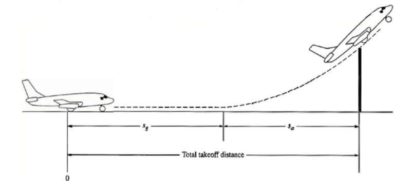
Take off is the phase of the flight where the airplane leaves the ground and becomes airborne. For aircrafts travelling vertically, this is known as liftoff. For light weight aircraft, usually full power is used for take off. For heavies aircrafts like passenger planes, full engine power is not used for take off, This will inccrease the life of engine, reduce maintanence cost and decreases the noise. In some emergency cases, the power used can then be increased to increase the aircraft's performance.
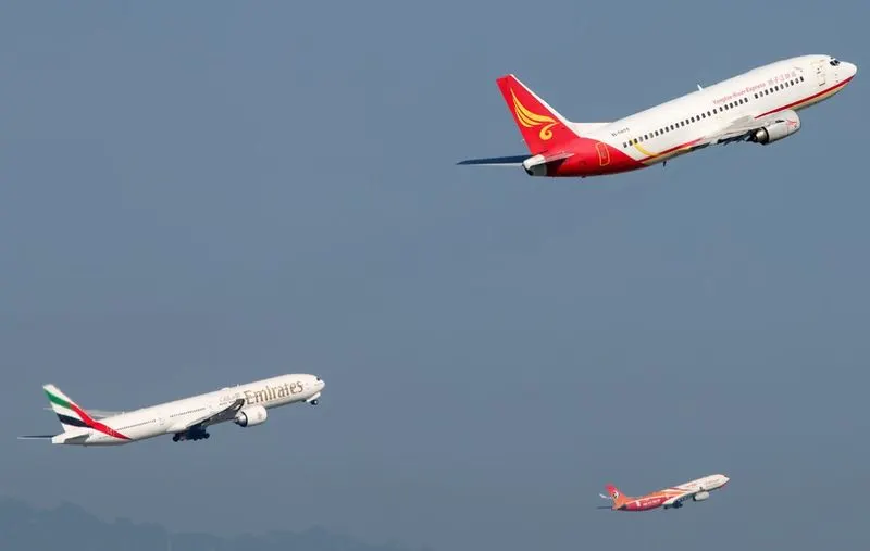
The takeoff speed required varies with aircraft weight and aircraft configuration (flap or slat position, as applicable), and is provided to the flight crew as indicated airspeed.
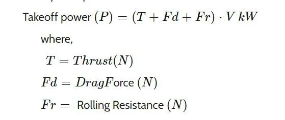
The formula is given by:
(b) Tire Design:
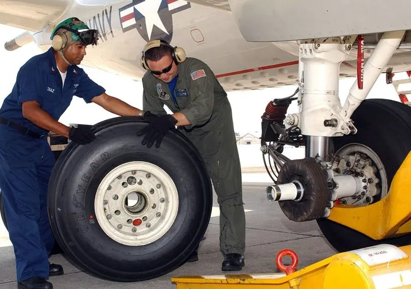
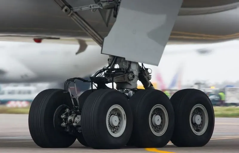
An aircraft tire or tyre is designed to withstand extremely heavy loads for short durations.The number of tires required for aircraft increases with the weight of the aircraft, as the weight of the airplane needs to be distributed more evenly. Aircraft tire tread patterns are designed to facilitate stability in high cross winds conditions, to channel water away to prevent hydroplaning, and for braking effect.
Aircraft tires also include fusible plugs (which are assembled on the inside of the wheels), designed to melt at a certain temperature. Tires often overheat if maximum braking is applied during an aborted takeoff or an emergency landing. The fuses provide a safer failure mode that prevents tire explosions by deflating in a controlled manner, thus minimizing damage to aircraft and objects in the surrounding environment.
Each of the twelve Boeing 777 main tires is inflated to 220 psi (15 bar; 1,500 kPa), weighs 120 kg (260 lb), has a diameter of 134 cm (53 in) and is changed every 300 cycles while the brakes are changed every 2000 cycles. Each tire is worth about $5,000. Aircraft tires generally operate at high pressures, up to 200 psi (14 bar; 1,400 kPa) for airliners, and even higher for business jets
tire construction
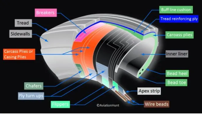
An aircraft tire is constructed for the purpose it serves. Unlike an automobile or truck tire, it does not have to carry a load for a long period of continuous operation. However, an aircraft tire must absorb the high impact loads of landing and be able to operate at high speeds even if only for a short time. The deflection built into an aircraft tire is more than twice that of an automobile tire. This enables it to handle the forces during landings without being damaged. Only tires designed for an aircraft as specified by the manufacturer should be used.
It is useful to the understanding of tire construction to identify the various components of a tire and the functions contributed to the overall characteristics of a tire
Bead
The tire bead is an important part of an aircraft tire. It anchors the tire carcass and provides a dimensioned, firm mounting surface for the tire on the wheel rim. Tire beads are strong. They are typically made from high-strength carbon steel wire bundles encased in rubber. One, two, or three bead bundles may be found on each side of the tire depending on its size and the load it is designed to handle.
Carcass Plies
Carcass plies, or casing plies as they are sometimes called, are used to form the tire. Each ply consists of fabric, usually nylon, sandwiched between two layers of rubber. The plies are applied in layers to give the tire strength and form the carcass body of the tire. The ends of each ply are anchored by wrapping them around the bead on both sides of the tire to form the ply turn-ups. As mentioned, the angle of the fiber in the ply is manipulated to create a bias tire or radial tire as desired. Typically, radial tires require fewer plies than bias tires.
Tread
he tread is the crown area of the tire designed to come in contact with the ground. It is a rubber compound formulated to resist wear, abrasion, cutting, and cracking. It also is made to resist heat build-up. Most modern aircraft tire tread is formed with circumferential grooves that create tire ribs. The grooves provide cooling and help channel water from under the tire in wet conditions to increase adhesion to the ground surface. Tires designed for aircraft frequently operated from unpaved surfaces may have some type of cross-tread pattern
Sidewall
Chine
(c)rolling resistance
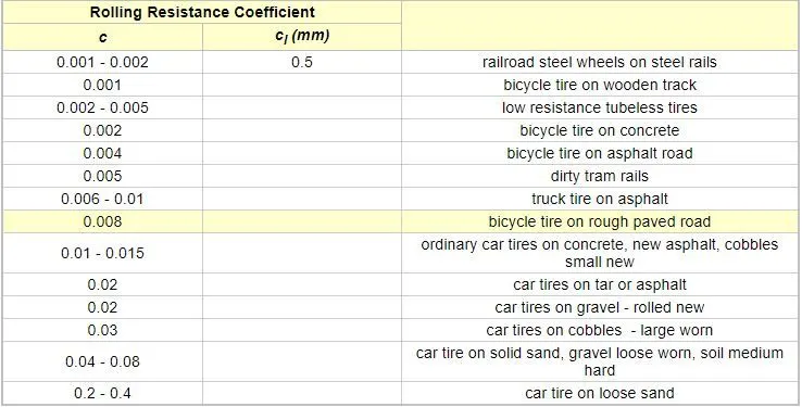
The force that resists the motion of a body rolling on a surface is called the rolling resistance or the rolling friction.
The rolling resistance can be expressed by the generic equation
Fr = c W (1)
where
Fr = rolling resistance or rolling friction (N, lbf)
c = rolling resistance coefficient - dimensionless (coefficient of rolling friction - CRF)
W = m ag
= normal force - or weight - of the body (N, lbf)
m = mass of body (kg, lb)
ag = acceleration due to gravity (9.81 m/s2, 32.174 ft/s2)
Note that the rolling resistance coefficient - c - is influenced by different variables like wheel design, rolling surface, wheel dimensions and more.
The rolling resistance can alternatively be expressed as
Fr = cl W / r (2)
where
cl = rolling resistance coefficient - dimension length (coefficient of rolling friction) (mm, in)
r = radius of wheel (mm, in)
(d) Tire Pressure
The typical airliner tire can handle a 38-ton load. It can meet the ground 500 times before needing a re-tread, a refresh it can take on seven times in its life.The key to their remarkable durability is maximizing the air pressure. The high-flying rubber is typically inflated to 200 psi, roughly six times what you put in an automobile tire, and the tires on an F-16 fighter are pumped to 320 psi. “It's really pressurized air that's so strong.
The sidewalls aren't terribly thick, and the strength of the tire lies in the cords embedded below the tread,They're typically nylon, and more recently a variety known as aramid. Each layer of the casing contributes to its load bearing and air pressure resisting capabilities. Of course, tires can fail, especially when under-inflated or overloaded. Treads can come off and casings can blow out.
In the first moments after a plane touches down, the tires are skidding, not rolling. The airplane essentially drags them down the runway until their rotational velocity matches the velocity of the plane. That's why they smoke upon landing, and why Michelin uses grooves instead of the block patterns seen on your car's rubber---blocks would simply break off. (Most tire wear comes from this moment of contact---where the rubber meets the runway.) The stoutest tires are rated for speeds of up to 288 mph.
(e) brake forces when landing
topping a 200-tonne aircraft landing at 180 mph requires a lot of braking force. To do this, the 787 has one brake unit on each of the eight wheels on the main gear assembly. On other aircraft types, the brake units are powered by the hydraulics system. An electrical signal is sent from the flight deck to hydraulic actuators near the main landing gear. Here, hydraulic fluid at 3,000 pound per square inch is used to force the brake unit against the wheel, thus slowing it down.
This system works fine, but the pipes and actuators that form this part of the hydraulic system come at a considerable weight cost. Extra weight means more fuel burn, which in turn increases costs and carbon emissions. What if the brakes could be powered a different way? When the pilots press on the brake pedals, an electrical signal is sent to the brake unit on the wheel. Here, electrically powered actuators are used to press the carbon brake disc against the wheel, slowing it down.
By changing to electric brakes, a 787-8 saves 141 pounds per aircraft and a 787-9 saves 245 pounds. The brakes are also known as “plug and play” because electrical wiring replaces the traditional hydraulics and it’s much easier and quicker to change the brake units when needed. Smart features also allow engineers to monitor the brake performance more closely, giving a real-time measurement of wear on the carbon disks.
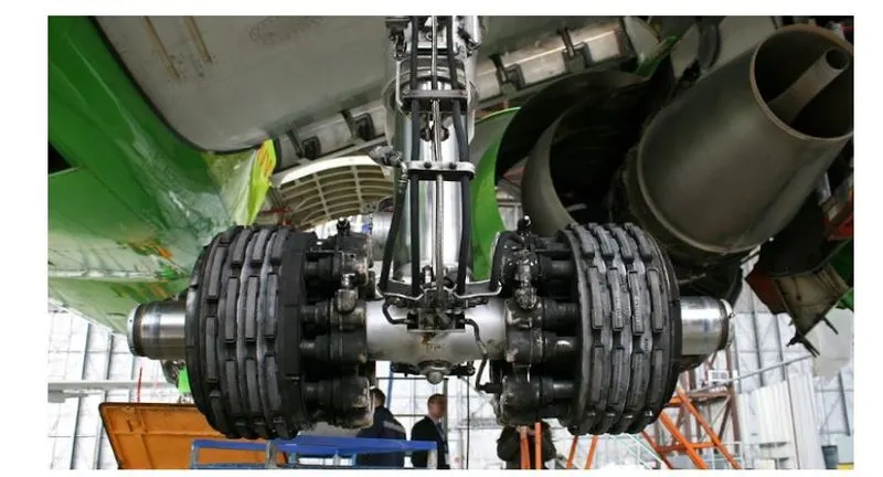
The following may be used to take the aircraft to a complete stop:
Anti-skid protection:
When landing on slippery runways, there’s a chance that the wheels may start to skid as the brakes are applied. To stop this from happening and to maintain maximum effective braking, each wheel has anti-skid protection.Using a variety of sources to determine the aircraft speed, the brake units know how fast the wheels should be spinning. If that speed drops significantly, it’s because the current brake pressure on that wheel is too great and the wheel is just skidding over the surface.
In this situation, the anti-skid system automatically reduces the braking on that wheel to a point where the skid stops before reapplying the pressure. All this is done in a fraction of a second.
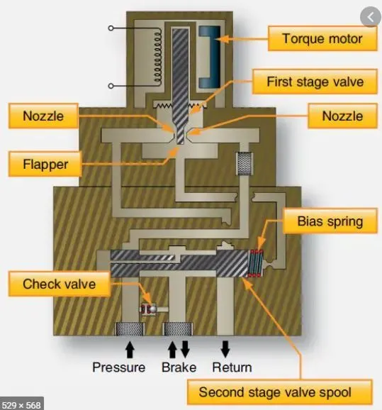
Autobrake
To help us get the braking underway as soon as we touch down, we have the autobrake system.This provides automatic braking at a preselected rate as soon as the aircraft senses that it is on the ground. It also provides full braking pressure in the case of a rejected takeoff if the speed is above 85 knots (98 mph).
Reverse Thrust
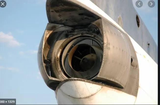
The final part of the braking process comes from reverse thrust. Just after we have touched down, we pull two levers on top of the thrust levers to engage the reverse thrust, a sort of “reverse gear” for jet engines. this causes blockers inside the engine to deploy and a door in the side of the engine to slide backward. The air which normally leaves the engine out the back is deflected forward by the blockers and out through the door.
This forward directed airflow helps slow the aircraft down but is most efficient at high speeds. If using max reverse, we drop this down to idle reverse at 60 knots (70 mph) and then back to normal thrust as we vacate the runway at around 20 knots (25 mph).
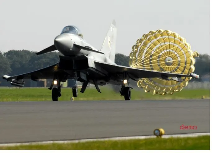
Drogue Parachutes
----------------------------------------------------------------------------------------------------------------------------------
PART B:
1. A. With necessary assumptions, calculate the force and power required to push/pull an aircraft by a towing vehicle.
B. Develop the model for the calculated force and power using Simulink.
ANS (A): The assumptions taken into consideration are :
- The runway is absolutely flat.
- The wind is zero.
- The speed of the aircraft is very minimum and constant throughout
The force to move the airplane is the rolling resistance between the airplane wheels and the tarmac.
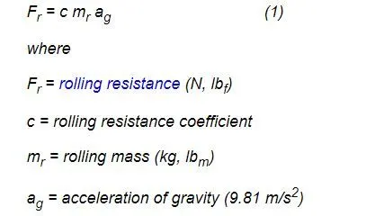
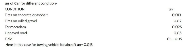
There are really two types of friction that come into play when pulling a plane. There is the frictional force between wheel and the axle as they rub together and then there is rolling friction. If you look at a tire closely, you will get a good sense of how rolling friction works. Although it looks round, it's not. The bottom of the tire is flatter than the rest of the tire because it's pushed against the ground. As the wheel rolls over, a new part of the tire has to be flatter—and it takes a force to deform this tire. That's the basic idea of rolling friction.
consider an example:
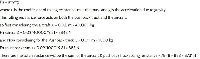
- In this, the hill climbing and aerodynamic factors are taken to be 0 since the values are negligible.
ANS (B):
The model is given below:
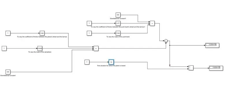
- The model is used to calculate the force which is to be overcome by the push-back vehicle in order to move the aircraft
- The blocks I have used are 1)the slider gain 2)product 3)sum 4)scope 5)constant
- The slider gain block was applied to vary the mass of the aircraft and push-back vehicle
- The same slider gain was used to vary the value of the coefficient of friction
- The constant block is used to give the value of g as 9.8
--------------------------------------------------------------------------------------------------------------------------------------
7. A. Design an electric powertrain with the type of motor, its power rating, and energy required to fulfill aircraft towing application in Simulink. Estimate the duty cycle range to control the aircraft speed from zero to highest. Make all required assumptions. Prepare a table of assumed parameters. Draw a block diagram of the powertrain.
(Hint: DC7 Block)
B. Also, Design the parameters in an excel sheet.
ANS (A): The details of the tow and aircraft is given below:
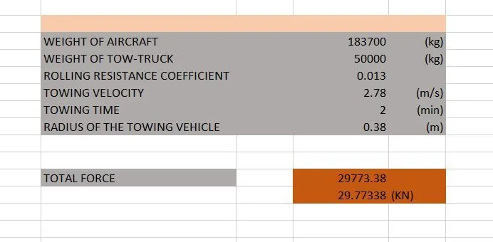
Now we calculate the required torque, power and energy required:
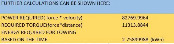
It can be seen that the total power required is 82.7 KW for the whole application. Since the motor details are given in HP, we make a conversion from KW to HP and determine the
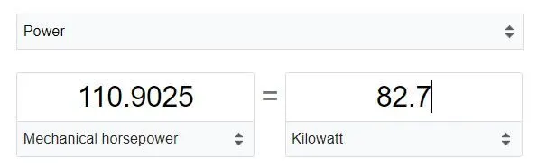
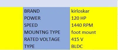
Therefore, the motor should be selected that can produce a HP a little greater than 110 HP.
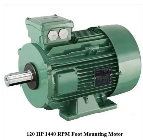
A motor that can be used is given above.
The duty cycle should be varied from:
(110/120 )*100
=91.6%
so it is from 0-0.916
This model can be made in Simulink. It is given below:
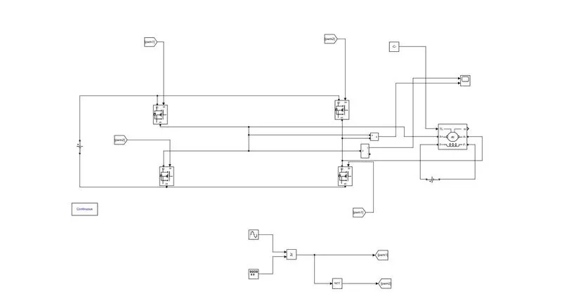
- The model takes the input from the SPWM and it is given into the 4 MOSFETs
- The power Gui block is implemented
- Goto and from blocks are used to take the signal and give it to the MOSFETS
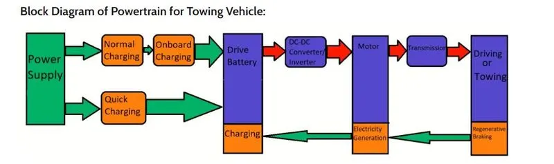
BLOCK DIAGRAM:
MOTOR PARAMETERS IN EXCEL SHEET
-------------------------------------------------------------------------------------------------------------------------------------------