Powertrain design for aircraft tow truck in runways
Project-1: Powertrain for aircraft towing tractor with Electric Powertrain in runways
AIM:
To study about the aircraft towing mechanism.
To study the load, speed and motor operating conditions for the tractor.
To design the electric drivetrain for estimated load requirements.
DESIGN PROCEDURE:
Reverse Engineering is used for design of any powertrain. The following steps are followed:
- The basic opwerating conditions, the road terrain, and speed variation (drive cycle).
- The input drive cycle then calculates the speed-torque characterstic of motor and hence rated power required.
- And comparing various types of motors which can deliver such power requirement.
Part A:
1. Search and list out the total weight of various types of aircrafts.
A. The basic powertrain load is distributed by the tractors payload and kerb load. The Kerb Load includes the aircraft load. The total aircraft load is a sum of Empty Aircraft Load, Fuel Load, Passenges and Luggage Load.
Following is a list of few aircrafts and their Maximum Takeoff and Landing weights:
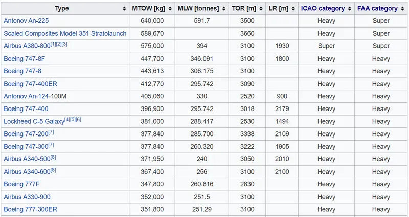
Where, `MTOW` is Maximum Takeoff Weight, `MLW` is Maximum Landing Weight, and `TOR` is TakeOff Run.
2. Is there any difference between ground speed and air speed?
A. Airspeed is the vector difference between the ground speed and the wind speed. On a perfectly still day, the airspeed is equal to the ground speed. But if the wind is blowing in the same direction that the aircraft is moving, the airspeed will be less than the ground speed. Therefore, it can be concluded that the Airspeed is as relative quantity and is dependent on the Wind Speed.
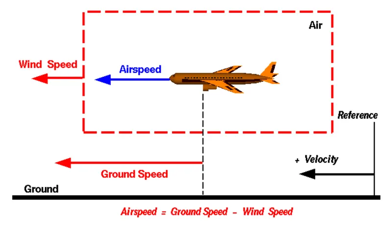
Based on the vecot notation of the wind and air speeds, the equation can deduce the required quantities.
3. Why is it not recommended to use aircraft engine power to move it on the ground at Airport?
A.
We are assuming passenger commuter aircraft and large airliners. Aircraft move using their own engine power all the time on the airport apron and taxiways under their own power to go towards runways and after landing taxi to their assigned gate.
The only time they use external assistance is to pushback from the gate. Large turbofan aircraft need help to reverse via a pushback tractor. The engines are turned on after the pushback is complete and the aircraft can move forward under It’s own power.
To be accurate, some aircraft can reverse using a variable pitch prop or thrust reversing on turbofans but generally reversing is done via pushback tractors. Blasting jet reversers blows debris In the crowded gate area creating foreign object damage hazard for adjacent aircraft, gate equipment or terminal waiting area glass windows.
4. How an aircraft is pushed to runway when its ready to take off?
A.
Pushbacks at busy aerodomes are usually subject to ground control clearance to facilitate ground movement on taxiways. Once clearance is obtained, the pilot will communicate with the tractor driver (or a ground handler walking alongside the aircraft in some cases) to start the pushback. To communicate, a headset may be connected near the nose gear.
Since the pilots cannot see what is behind the aircraft, steering is done by the pushback tractor driver and not by the pilots. Depending on the aircraft type and airline procedure, a bypass pin may be temporarily installed into the nose gear to disconnect it from the aircraft's normal steering mechanism.
Once the pushback is completed, the towbar is disconnected, and any bypass pin removed. The ground handler will show the bypass pin to the pilots to make it clear that it has been removed. The pushback is then complete, and the aircraft can taxi forward under its own power.
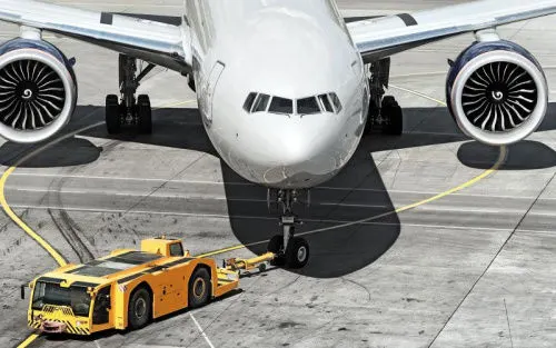
Large aircraft cannot be moved by hand and must have a tractor or tug. Pushback tractors use a low profile design to fit under the aircraft nose. For sufficient traction the tractor must be heavy, and most models can have extra ballast added. A typical tractor for large aircraft weighs up to 54 tonnes (59.5 short tons; 53.1 long tons; 119,000 pounds) and has a drawbar pull of 334 kN (75,000 lbf). Often the driver's cabin can be raised for increased visibility when reversing and lowered to fit under aircraft. There are two types of pushback tractors: conventional and towbarless (TBL).
5. Learn about take off power, tyre design, rolling resistance, tyre pressure, brake forces when landing.
A.
Take Off Power:
For light aircrafts, usually full power is used during takeoff. Large transport category (airliner) aircraft may use a reduced power for takeoff, where less than full power is applied in order to prolong engine life, reduce maintenance costs and reduce noise emissions. In some emergency cases, the power used can then be increased to increase the aircraft's performance. Before takeoff, the engines, particularly piston engines, are routinely run up at high power to check for engine-related problems. The aircraft is permitted to accelerate to rotation speed (often referred to as Vr). The term rotation is used because the aircraft pivots around the axis of its main landing gear while still on the ground, usually because of gentle manipulation of the flight controls to make or facilitate this change in aircraft attitude (once proper air displacement occurs under / over the wings, an aircraft will lift off on its own; controls are to ease that in).
The nose is raised to a nominal 5°–15° nose up pitch attitude to increase lift from the wings and effect liftoff. For most aircraft, attempting a takeoff without a pitch-up would require cruise speeds while still on the runway.
Tyre Design and Pressure:
Designing aircraft tires is a very intense undertaking. Once an aircraft manufacturer goes to the tire manufacturer with the size and weight requirements, the tire manufacturer begins the process of designing a tire that meets the needs of the aircraft manufacturer as well as all regulatory requirements — including foreign regulations in many cases.
Engineers are challenged with designing tires with cool running, heat-resistant materials while simultaneously exceeding tire service requirements. Tire prototypes are put through rigorous tests that simulate cycles of landings, take-offs, and taxi operations. It is only after the tires pass all mandatory tests and meet the requirements of the aircraft manufacturer and airworthiness authorities that the tires are put into production.
Two types of tires are used in aircraft applications — bias-ply tires and radial tires. Although both types of tires share some similarities in design, there are differences that need to be noted.
Bias-ply tire construction
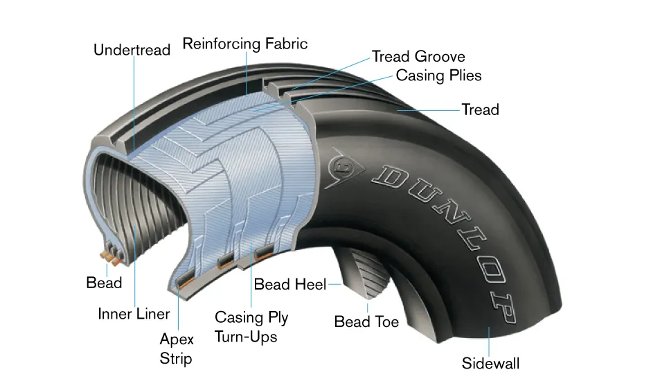
A cutaway of a typical bias-ply tire is shown in Figure 1. Bias-ply tires are popular choices for aircraft tires because of their durability and retreadability. The tire construction consists of the following components:
Tread: The tread is made of rubber mixed with other additives to obtain the desired level of toughness, durability, and resistance to wear. The tread pattern is designed to aircraft operational requirements, with the ribbed tread design used widely due to its good traction under varying runway conditions.
Sidewall: The sidewall is a protective layer of rubber that covers the outer casing ply. It extends from the tread edge to the bead area.
Tread Reinforcing Ply: One or more layers of fabric that strengthens and stabilizes the tread area for high-speed operation. It also serves as a reference for the buffing process when tires are retreaded.
Buff Line Cushion: The buff line cushion is made of rubber compound to enhance the adhesion between the tread reinforcing ply and the breakers or casing plies. It is of sufficient thickness to allow for the removal of the old tread when the tire is retreaded.
Breakers: Breakers are reinforcing plies of rubber-coated fabric placed under the buff line cushion to protect casing plies and strengthen and stabilize the tread area. They are considered an integral part of the casing construction.
Casing Plies: Alternate layers of rubber-coated fabric (running at opposite angles to one another) provide the strength of the tire.
Wire Beads: Hoops of high tensile strength steel wire that anchor the casing plies and provide a firm mounting surface on the wheel. The outer edge of the bead that fits against the wheel flange is called the bead heel. The inner bead edge is called the bead toe.
Apex Strip: A wedge of rubber affixed to the top of the bead bundle.
Flippers: Layers of rubberized fabric that help anchor the bead wires to the casing and improve the durability of the tire.
Ply Turnups: The casing plies are anchored by wrapping them around the wire beads, thus forming the ply turnups.
Chafer: A protective layer of rubber and/or fabric located between the casing plies and wheel to minimize chafing.
Liner: In tubeless tires, the liner is a layer of low permeability rubber that acts as a built-in tube and restricts gas from diffusing into the casing plies. In tube-type tires, a thinner liner is used to prevent tube chafing against the inside ply.
Radial-ply tire construction
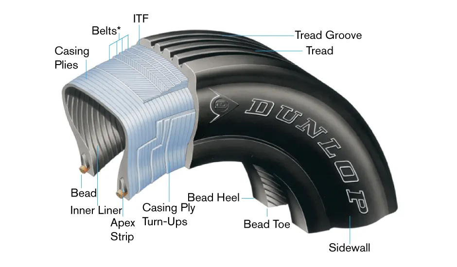
A typical radial tire is illustrated in Figure 2. With their rigid belt, they provide increased landings and reduced rolling resistance. They have fewer components in their construction and are lighter than similarly sized bias ply tires. Components that differ from bias-ply construction as follows:
Overlay: A layer of reinforcing rubber coated fabric placed on top of the belts to aid in high speed operation.
Belt Plies: A composite structure that stiffens the tread area for increased landings. The belt plies increase the tire strength in the tread area.
Casing Plies: As in bias-ply tires, the casing plies are layers of rubber-coated fabric. However, unlike those in bias plies that run at opposite angles to one another, radial plies run radially from bead to bead.
Chippers: The chippers are layers of rubber-coated fabric applied at diagonal angles that improve the durability of the tire in the bead area.
Each of the twelve Boeing 777 300ER main tires is inflated to 220 psi (15 bar; 1,500 kPa), weighs 120 kg (260 lb), has a diameter of 134 cm (53 in) and is changed every 300 cycles while the brakes are changed every 2000 cycles. Each tire is worth about $5,000. Aircraft tires generally operate at high pressures, up to 200 psi (14 bar; 1,400 kPa) for airliners, and even higher for business jets. The main landing gear on the Concorde was typically inflated to 232 psi (16.0 bar), whilst its tail bumper gear tires were as high as 294 psi (20.3 bar). The high pressure and weight load on the Concorde tyres were a significant factor in the loss of Air France Flight 4590.
Rolling Resistance:
The main difference between radial and bias ply tyres is in the belt construction. The cord materials too are different, leading to changes in the functional performance of the tyres.
Radial Ply:
In radial tyres the steel belts run at a 90-degree angle with the tread line. It allows the sidewall and the tread of the tyre to function independently. Thus, there is low sidewall flex and more contact with the ground.
Bias Ply:
In bias ply tyres the nylon belts run at 30 to 45-degree angle with the tread line. The multiple, over lapping rubber plies in these tyres connect the sidewall and tread. The stiff internal construction causes less contact with the ground and may result in overheating.
Therefore, more rolling resistance is generated in Bias Ply and is not suitable for fuel economic functioning.
Braking Force:
Aircraft braking systems include:
- Aircraft Disc Brakes in the landing gear, used to brake the wheels while touching the ground. These brakes are operated hydraulically or pneumatically. In most modern aircraft they are activated by the top section of the rudder pedals ("toe brakes"). In some older aircraft the bottom section is used instead ("heel brakes"). Levers are used in a few aircraft. Most aircraft are capable of differential braking.
- Thrust Reverser, that allow thrust from the engines to be used to slow the aircraft.
- Air Brakes, dedicated flight control surface that work by increasing drag.
- Large drogue parachutes, used by several former and current military and civilian aircraft (examples include the American B-52 and the soviet TU-134 and TU-144) and in the Space Shuttle.
6.
(a) With necessary assumptions, calculate the force and power required to push / pull an aircraft by a towing vehicle.
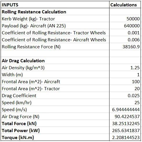
The following calculations were done for the Aerodynamic drag, Rolling Resistance Force of the tractor:
Aerodynamic Drag: `1/2rhoAv^2C_d`
Rolling Resistance Force: `mu_(rr)mg`
Force Torque Relation: `F_(te)=TG/r`
Where Radius of Motor is `25 text(in)=0.625m`
Gear Ratio is 11.
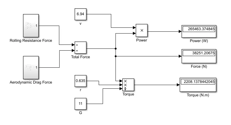
(b) Develop the model for the calculated force and power using Simulink.
7.
(a)Design an electric powertrain with type of motor, it’s power rating, and energy requirement to fulfill aircraft towing application in Simulink. Estimate the duty cycle range to control the aircraft speed from zero to highest. Make all required assumptions. Prepare a table of assumed parameters. Draw a block diagram of powertrain. (Hint :DC7 Block)
(b) Also, Design the parameters in excel sheet.
A.
DESIGN OF ELECTRIC POWERTRAIN:
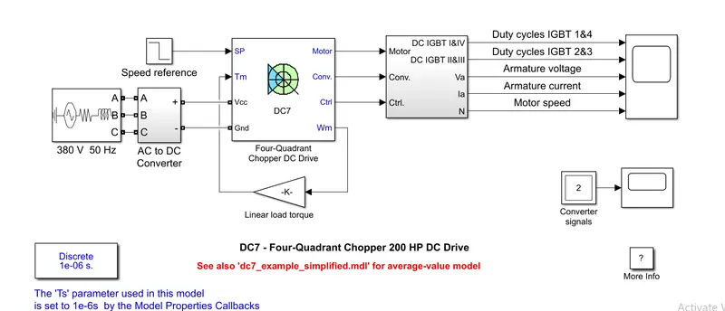
1. Energy Requirement for Vehicle
2. Motor Selection based on power requirements
3. Power Converters to step up current to armature
4. Duty Cycle Switching for Speed Control
Assuming 10 mins to tow the aircraft:
Energy= Power x Time
= 265.63 x 0.16
Energy= 42.5 kWh
Motor Selection:
Assuming BLDC Motor
The following parameters are to extracted for Motor Parameters and selection:
`n_0` No Load speed
`I_0` No Load current
`T_H` Stall Torque
`R` Terminal Resistance
Friction Torque `T_R=k_M.I_o`
where `k_M` is torque constant
`k_m=T/sqrt(P_(text(in))-P_(out))`
`k_M=k_msqrtR`
`V=I.R+V_(bf)`
Where `V` is Power Supply, `I` is current, `V_(bf)` is Back EMF
Using these equations the optimal voltage and terminal resistance for motor is found out.
Power Converter:
A DC-DC Boost converter is used to convert the DC Battery voltage to stepped up DC Motor voltage. A bidirectional DC-DC Converter is advised for regenerative braking application also.
Speed Control:
A duty cycle is used to output the required voltage based on the constant input voltage provided by battery.
Motor terminal Voltage= Armature Voltage* Duty Cycle
Based on the required acceleration/deceleration, the duty cycle is varied and the voltage is sent to control the motor.