Project-1: Powertrain for aircraft in runways
AIM :-
This project is divided into two parts A and B where,
Aim of Part-A is,
- To list out the total weight of various types of aircrafts.
- To explain the difference between air speed and ground speed.
- To explain why the aircraft's engine power is not recommended to be used when on the ground.
- To explain how an aircraft is pushed towards the runway before take off.
- To understand take off power, rolling resistance, tire design and pressure, and the braking forces during landing.
Aim of Part-B is,
- To calculate the forces and power required by a towing vehicle to push/pull the aircraft on the ground and to develop a model using Simulink.
- To design an electric powertrain for aircraft towing application on Simulink and and to design the parameters on Excel.
PART-A :-
1. LIST OF THE TOTAL WEIGHT OF VARIOUS TYPES OF AIRCRAFTS :-
In the aviation industry there are different types of aircraft weights and they are,
- Manufacturer's Empty Weight: It is the weight of the aircraft as built and includes the weight of the structure, power plant, furnishings, installations, systems and other equipment that are considered an integral part of an aircraft. It excludes baggages, passengers and fuel.
- Zero Fuel Weight: This is the total weight of the aircraft and all it's contents including unusable fuel but the useable fuel is not included here. As a flight progresses and fuel is consumed, the total weight of the airplane reduces, but the ZFW remains constant. Maximum zero fuel weight (MZFW) is the maximum weight allowed before usable fuel and other specified usable agents (engine injection fluid, and other consumable propulsion agents) are loaded.
- Operating Empty Weight: It is the basic weight of an aircraft including the crew, all fluids necessary for operation such as engine oil, engine coolant, water, unusable fuel and all operator items and equipment required for flight but excluding usable fuel and the payload.
- Payload: It is the carrying capacity of an aircraft. It includes cargo, people, extra fuel. In the case of a commercial airliner, it may refer only to revenue-generating cargo or paying passengers.
- Maximum Take Off Weight: This is the maximum weight at which the pilot of the aircraft is allowed to attempt to take off.
- Regulated Take Off Weight: Depending on different factors (e.g. flap setting, altitude, air temperature, length of runway), RTOW or maximum permissible takeoff weight varies for each takeoff. It can never be higher than MTOW.
- Maximum Landing Weight: The maximum weight at which the aircraft is permitted to land.
- Maximum Ramp Weight: Also called as the Maximum Taxi Weight. It is the maximum permissible weight authorised for manouvering the aircraft on the ground.
- Gross Aircraft Weight: It is the total aircraft weight at any moment during the flight or ground operation. This decreases during flight due to fuel and oil consumption.
There are different classifications of aircrafts in both the civil and defence industries. The aircrafts as classified by the Federal Aviation Administration (FAA) are,
- Light or small aircraft which have a gross aircraft weight of 5670 Kg or less. These aircraft are used commercially for passenger and freight transport, sightseeing, photography, and other roles, as well as personal use. Examples of this aircraft include De-havilland Canada DHC-6 twin otter and Embrear EMB-500 Phenom 100.
- Medium aircraft which have a gross weight of 7000 Kg to 125000 Kg. These aircrafts are used commercially in the civil aviation for carrying people or transporting cargo. Examples of this aricraft include Boeing 737, Airbus A319 and Douglas DC-8-51.
- Large or heavy aircraft which have a gross weight from 140000 Kg to 447700 Kg. These aircrafts are used for long distance inter continental travel as commercial airlines ferrying people or a cargo services ferrying goods. Examples of this aircraft include, Boeing 747, Airbus A340, Antonov AN-124 and Lockheed C-5 Galaxy.
- Super aircrafts are the largest transport aircraft and only two exist in the world. The Airbus A380 having a gross weight of 575000 Kg and the Antonov An-225 having a gross weight of 640000 Kg. The Airbus is used as a commercial aircraft for people and the Antonov is a cargo plane.
2. THE DIFFERENCE BETWEEN AIR SPEED AND GROUND SPEED :-
The speed of an aircraft is considered two ways, the air speed and the ground speed.
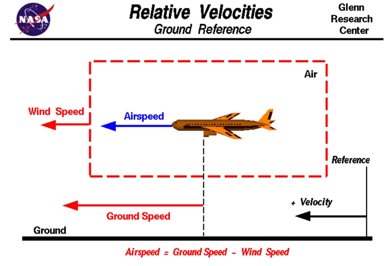
Airspeed is the speed at which the aircraft is moving relative to the air it is flying in. It is also the speed at which air flows around the wings.
Ground speed is the speed of the aircraft relative to the ground. Here the speed is considered horizontal and not vertical, where an aricraft climbing vertically is said to have zero ground speed.
Air speed determines if there is enough wind flowing around the wings to generate lift and make it fly and ground speed determines how fast the aircraft takes to reach it's destination.
The relationship between air speed and ground speed lies in the wind speed. Where the ground speed is the sum of air speed and wind speed. So if the aircraft is travelling in the same direction the wind is blowing as shown in the figure above, it experiences tailwind and the ground speed is greater than the air speed. If the wind is blowing in the opposite direction then the aircraft experiences headwind and the due to the resistance of the head wind the ground speed is lesser than the air speed.
Let us consider an example. Assume that an aircraft is travelling with an air speed of 500 Km/hr and has to cover a ground distance of 2000 Km.
If there is no wind at all then the air speed = ground speed = 500 Km/hr and the aircraft will take 4 hours to cover 2000 Km.
If the aircraft experiences headwind of 100 Km/hr while having the same speed, the ground speed decreases to 400 Km/hr which would increase the time taken to cover the distance by 1 hour which is 5 hours to cover 2000 Km.
If the aricraft experiences tailwind of the same speed 100 Km/hr having the same air speed, then the ground speed increases beacause the air resistance is significantly less and the ground speed then increases to 600 Km/hr. This will shorten the time taken to cover the distance by 1.2 hours which is 3.3 hours to cover 2000 Km.
Therefore for pilots both air speed and ground speed are very important. The former helps them know if the aircraft will not stall and the latter helps them know how long it will take to reach their destination.
3. WHY AIRCRAFT ENGINE'S POWER ARE NOT RECOMMEND TO PROPEL THE AIRCRAFT ON THE GROUND :-
Commercial aircrafts are equipped with engines rated from 18,000 to nearly 100,000 lbs of thrust. Such thrust levels provide for safe takeoff, flight, and landing over a wide range of temperatures, altitudes, gross weights, and payload conditions. However, the exhaust wake from these engines can pose hazards in commercial airport environments. Operators and airport authorities must carefully consider these hazards and the resulting potential for injury to people and damage to or caused by baggage carts, service vehicles, airport infrastructure, and other airplanes.
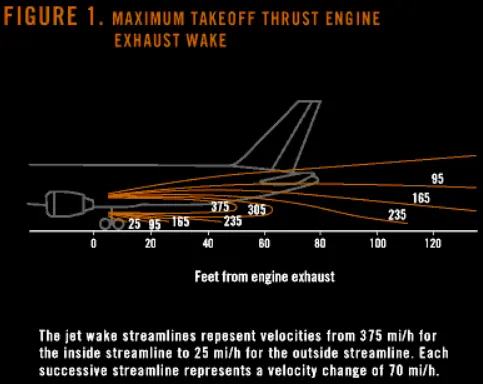
When modern jet engines are operated at rated thrust levels, the exhaust wake can exceed 603 Km/hr from the engine exhaust nozzle. This exhaust flow field extends in a rapidly expanding cone, with portions of the flow field contacting and extending along the pavement surface as shown in the figure above. Exhaust velocity components are attenuated with increasing distance from the engine exhaust nozzle. However, an airflow of 483 km/h can still be present at the empennage, and significant people and equipment hazards will persist hundreds of feet beyond this area. At full power, the exhaust wake speed can typically be 240 km/h at 200 ft beyond the airplane and 80 to 161 km/h well beyond this point.
If the power from the engine's aircraft is high when on the ground, the thrust produced can lead to Foreign Object Damage or FOD which can damage the aircraft's structure and/or equipments and personnel. Debris from the ground wether on the taxiway or runway can get sucked into the engine and can not only damage the components inside the engine but also the stabilizers, elevators or fuselage.
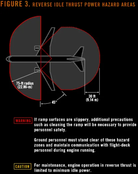
Thrust from the engine can also blow any ground equipment away if in case they are not fastened and can also harm ground personnel either from the suction force of the engine blades or from the exhaust wake or due to flying debris or equipment hitting them. The figure above shows the hazardous zones of an engine when the aircraft is on the ground and this can also include the thrust required for taxiing.
Therefore due to the high thrust produced by the engine, it is not recommended to use the engine's power when it is on the ground if it is stationary or taxiing due to the exahust wake and the force produced by the intake blades.
4. HOW ARE AIRCRAFTS PUSHED TOWARDS THE RUNWAY BEFORE TAKE OFF :-
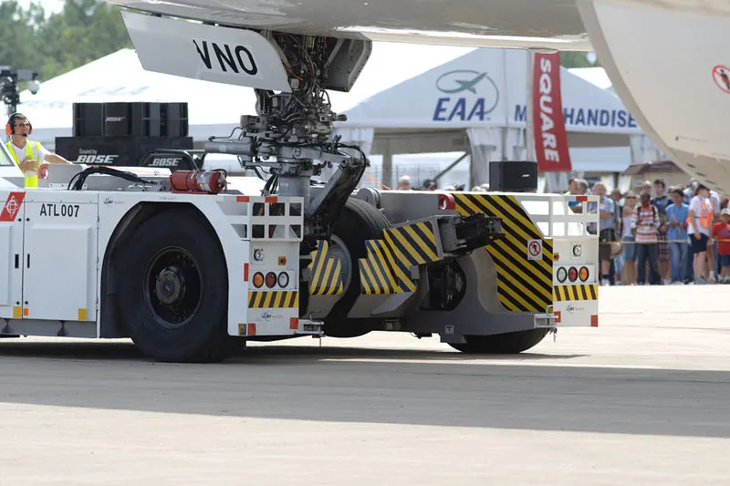
Due to the high thrust developed by jet engines it is not advisable to use the engine's power for propulsion on the ground except during taxiing but between the taxiway and the runway. During departure or if an aricraft is parked in a hangar, aircraft engines be it jet or turboprop cannot reverse. In order to push or pull the aircraft to the taxiway, a towing tug or a tow tractor is used to move the aircraft around on the ground.
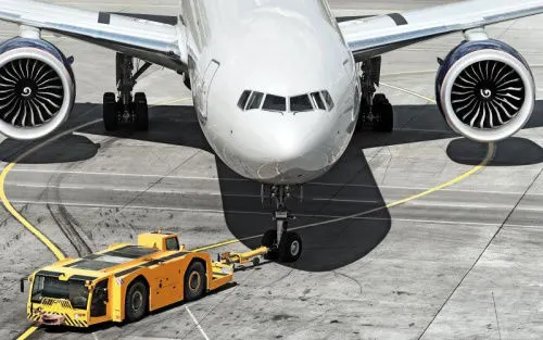
Pushback tractors use a low profile design to fit under the aircraft nose. For sufficient traction the tug must be heavy, and most models can have extra ballast added. A typical tug for large aircraft weighs up to 54 tonnes and has a drawbar pull of 334 kN. Often the driver's cabin can be raised for increased visibility when reversing and lowered to fit under aircraft. There are two types of pushback tractors: conventional and towbarless (TBL).
- Conventional Tow Tugs: Conventional tugs use a tow bar to connect the tug to the nose landing gear of the aircraft. The tow bar is fixed laterally at the nose landing gear, but may move slightly vertically for height adjustment. At the end that attaches to the tug, the tow bar may pivot freely laterally and vertically. In this manner the tow bar acts as a large lever to rotate the nose landing gear. Each aircraft type has a unique tow fitting so the towbar also acts as an adapter between the standard-sized tow pin on the tug and the type-specific fitting on the aircraft's landing gear. The tow bar must be long enough to place the tug far away enough to avoid hitting the aircraft and to provide sufficient leverage to facilitate turns. The tow bar can be connected at the front or the rear of the tractor, depending on whether the aircraft will be pushed or pulled. The towbar has a shear pin which prevents the aircraft from being mishandled by the tug, when overstressed the shear pin will snap, disconnecting the bar from the nose gear to prevent damage to the aircraft and tug.
- Towbar-Less Tugs: Towbarless (TBL) tugs do not use a towbar, they scoop up the nose landing gear and lift it off the ground. This avoids the time penalty of connecting/disconnecting a towbar, and entirely removes the cost/complexity of maintaining towbars on the ramp. The tug itself does not need to be particularly massive - the aircraft's nosewheel weight provides the necessary downward force. A TBL tug is much shorter and has one only a single pivot point instead of one at either end of the towbar, so it has much simpler and precise control of the aircraft. This is very useful in general aviation settings with a wider variety of aircraft in more confined spaces than their airline counterparts.
5. WHAT ARE TAKE OF POWER, ROLLING RESISTANCE, TIRE DESIGN, TIRE PRESSURE AND BRAKING FORCES DURING LANDING :-
Take Off Power :-
Take off is the horizontal distance covered on the ground to get an aircraft airborne. This is done by having the aircraft travel a certain distance known as the ground run upon which the control stick is pulled to lift the aircraft's nose. This creates an angle of attack to attain the lift co-efficient and the air acting on the wings generates lift and the aircraft then gets airborne. In light aricrafts 100% of the power is used for take off where as for heavier aircrafts about 85% engine power is used for take off in order to prolong the engine life. The equation to calculate the take off power is,
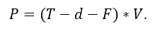
Where,
T = Thrust devloped by the engine.
d = Aerodynamic drag.
F = Rolling resistance of the aircraft.
Rolling Resistance :-
Also known as rolling friction, it is the resistance force of a spherical or round object when subjected to motion on a surface.With respect to aircrafts rolling resistance is the friction produced at the wheels during take off and landing. The equation of rolling resistance is given as,
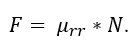
Where,
Urr = Co-efficient of friction
N = Normal force which is the force perpendicular to the surface on which the wheel is rolling.
Aircraft Tire Design :-
Aircraft tires may be tube-type or tubeless. They support the weight of the aircraft while it is on the ground and provide the necessary traction for braking and stopping. The tires also help absorb the shock of landing and cushion the roughness of takeoff, rollout, and taxi operations. Aircraft tires must be carefully maintained to perform as required. They accept a variety of static and dynamic stresses and must do so dependably in a wide range of operating conditions. Aircraft tires are classified in various ways by type, ply rating, whether they are tube-type or tubeless, and whether they are bias ply tires or radials. Identifying a tire by its dimensions is also used. The various types of tires are,
Type I tires which are used on fixed gear aircraft and are designated only by their nominal overall diameter in inches. These are smooth profile tires that are obsolete for use in the modern aviation fleet. They may be found on older aircraft.
Type III tires are common general aviation tires. They are typically used on light aircraft with landing speeds of 160 miles per hour or less. Type III tires are relatively low-pressure tires that have small rim diameters when compared to the overall width of the tire. They are designed to cushion and provide flotation from a relatively large footprint.
Type VII tires are high performance tires found on jet aircraft. They are inflated to high-pressure and have exceptional high load carrying capability. The section width of Type VII tires is typically narrower than Type III tires.
Type VIII aircraft tires are also known as three-part nomenclature tires. They are inflated to very high-pressure and are used on high-performance jet aircraft. The typical Type VIII tire has relatively low profile and is capable of operating at very high speeds and very high loads. It is the most modern design of all tire types. The three-part nomenclature is a combination of Type III and Type VII nomenclature where the overall tire diameter, section width, and rim diameter are used to identify the tire.
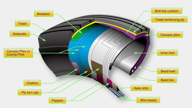
An aircraft tire is constructed for the purpose it serves. Unlike an automobile or truck tire, it does not have to carry a load for a long period of continuous operation. However, an aircraft tire must absorb the high impact loads of landing and be able to operate at high speeds even if only for a short time. The deflection built into an aircraft tire is more than twice that of an automobile tire. This enables it to handle the forces during landings without being damaged. The construction of an aircraft tire is shown above.
- Tire Bead: The tire bead is an important part of an aircraft tire. It anchors the tire carcass and provides a dimensioned, firm mounting surface for the tire on the wheel rim. Tire beads are strong. They are typically made from high-strength carbon steel wire bundles encased in rubber. One, two, or three bead bundles may be found on each side of the tire depending on its size and the load it is designed to handle. Radial tires have a single bead bundle on each side of the tire. The bead transfers the impact loads and deflection forces to the wheel rim.
- Carcass plies: Carcass plies, or casing plies as they are sometimes called, are used to form the tire. Each ply consists of fabric, usually nylon, sandwiched between two layers of rubber. The plies are applied in layers to give the tire strength and form the carcass body of the tire. The ends of each ply are anchored by wrapping them around the bead on both sides of the tire to form the ply turn-ups. As mentioned, the angle of the fiber in the ply is manipulated to create a bias tire or radial tire as desired. Typically, radial tires require fewer plies than bias tires.
- Tread: The tread is the crown area of the tire designed to come in contact with the ground. It is a rubber compound formulated to resist wear, abrasion, cutting, and cracking. It also is made to resist heat build-up. Most modern aircraft tire tread is formed with circumferential grooves that create tire ribs. The grooves provide cooling and help channel water from under the tire in wet conditions to increase adhesion to the ground surface. Tires designed for aircraft frequently operated from unpaved surfaces may have some type of cross-tread pattern. The tread is designed to stabilize the aircraft on the operating surface and wears with use.
- Sidewall: The sidewall of an aircraft tire is a layer of rubber designed to protect the carcass plies. It may contain compounds designed to resist the negative effects of ozone on the tire. It also is the area where information about the tire is contained. The tire sidewall imparts little strength to the cord body. Its main function is protection.
Aircraft Tire Pressure :-
Aircraft tires are not the same as passenger car or truck tires. Unlike car tire, aircraft tires are not on the ground at all times and are only in contact with the ground during take off, landing and taxing. Particularly during take off and landing, the tires must be able to withstand extremely heavy impact loads for short durations. The figure below is a comparison between a car tire and aircraft tires.
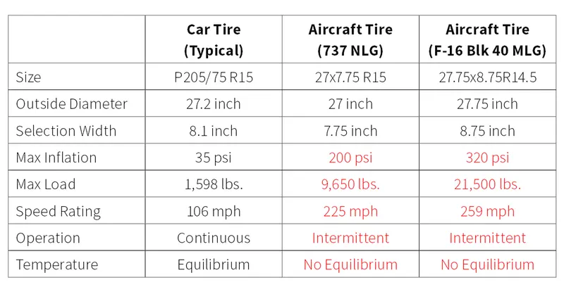
Because aircraft tires operate at such high extremes of pressure, load, and speed, their care and service is critically important. The most important action an operator can take to prevent tire-related events is to maintain proper tire inflation pressure. Failure to keep aircraft tires properly inflated can lead to very serious consequences. The most serious of these is the structural failure of the tire. If the tire operates underinflated or overdeflected/overloaded, the nylon cords which form the structure of the tire go in and out of compression as the tire rotates. This weakens the cords – much like a paperclip which is bent back and forth – until eventually the cords break. If enough cords break, the entire structure will eventually fail.
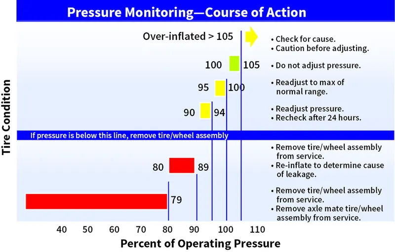
It is important to check the tire pressure everyday because of the high pressures and extreme temperatures at which aircraft tires operate, they do not hold air perfectly. An aircraft tire can lose up to 5 percent of its pressure in 24 hours and still be perfectly serviceable.
Braking Forces During Landing :-
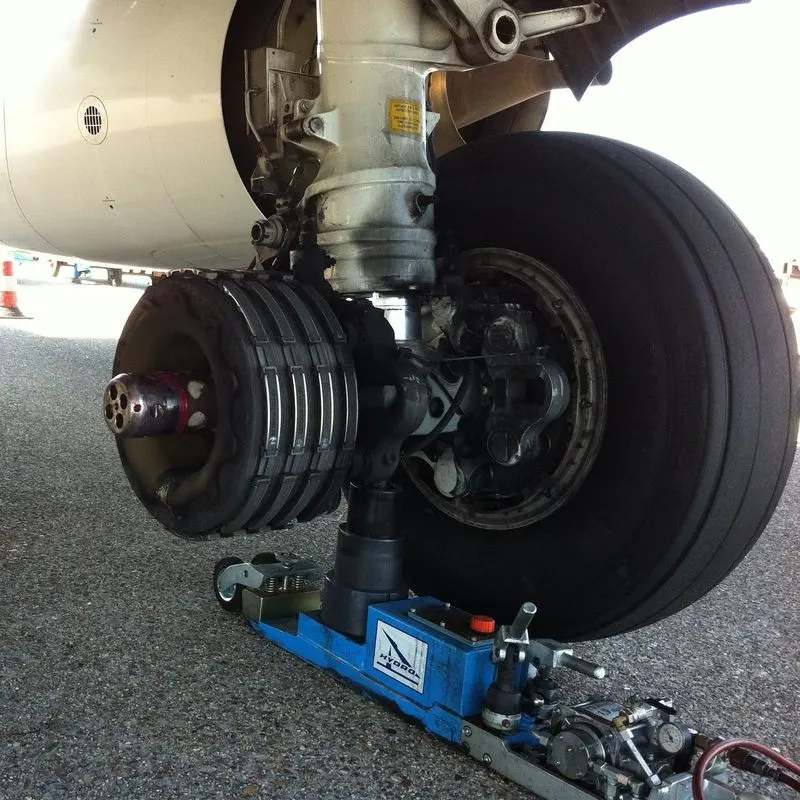
Like a car aircrafts have disc brakes at the wheels to slow down the aircraft when it touches down, but the disc brakes alone are not sufficient for the plane to decelerate quickly and safely. Therefore air brakes and in some aircrafts reverse thrusters are used along with the disc brakes to safely bring the aircraft to a halt after landing. The braking process exerts a torque on the wheels due to which friction is produced. As a result, friction is produced with the ground, and it loses kinetic energy, and hence, the vehicle stops.
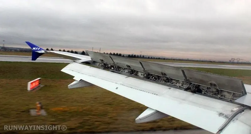
Friction, however, is massively dependent on the weight that rests on the wheels. In case of landing an airplane, the aerodynamic lift basically nullifies the weight of the plane and therefore makes braking while using the wheels extremely inefficient. As a result, the plane needs other ways to slow down until the aerodynamic lift and speed is sufficiently reduced. In modern aviation, this is done by two different braking systems: The Spoilers and the Reversers, that both are usually operated by a computer, which tries to reach a constant deceleration of convenient magnitude.
As soon as the wheels get in contact with the ground, the Spoilers are fully activated. These are flaps located on the back-end of the wings and can significantly reduce the aerodynamic lift as well as increase the drag. These flaps are extremely important for the braking process because without them the friction of the wheels is not sufficient for efficient braking. Basically, wheel brakes and Spoilers together can already be sufficient for slowing down an airplane.
However, to reduce the amount of stress the wheel brakes have to withstand, there is an additional system reversers. These are mechanisms located at the engines that can be activated to redirect the engine’s exhaust forward, rather than backwards (commonly referred to as thrust reversal). All three systems together can be used by a computer to reach an extremely smooth braking process without putting too much stress on the single components.
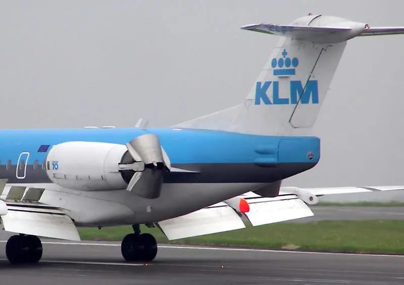
These 3 systems the disc brake, air brake or spoilers and the reverse thrusters together help bring the aircraft to a stop safely.
PART-B :-
6. CALCULATE THE FORCE AND POWER REQUIRED TO PUSH/PULL AND AIRCRAFT USING A TOWING TUG :-
In order to calculate the power required by the towing tug to push/pull an aircraft, we must first calculate the forces that act on the vehicle. Since aircrafts operate on flat surfaces on the ground, the hill climbing force is not taken into consideration. Therefore the two forces acting on the towing tug during operation are aerodynamic drag force and rolling resistance force.
Calculation of rolling resistance,
The equation of rolling resistance is,
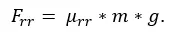
Where,
Urr is the co-efficient of friction.
m is the mass of the vehicle and the mass of the aircraft in Kg.
g is the acceleration due to gravity in m/s^2.
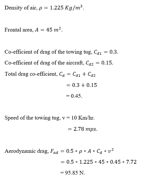
The equation for aerodynamic drag is,

Where,
P is the density of air in Kg/m^3.
Cd is the co-efficient of drag.
v is the speed of the towing tug in m/s.
The power required for the towing tug to push/pull the aircraft.
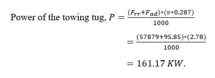
Therefore the forces and the power require for the tow tug to push/pull and aircraft are,
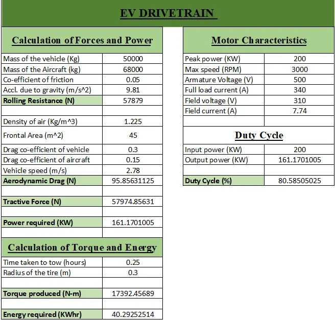
Rolling resistance force = 57879 N.
Aerodynamic drag force = 95.85 N.
Power required to tow the aircraft = 161.17 KW.
7. DESIGN AN ELECTRIC POWERTRAIN ON SIMULINK TO TOW AN AIRCRAFT WITH MOTOR TYPE, POWER RATING, ENERGY REQUIREMENT AND DUTY CYCLE :-
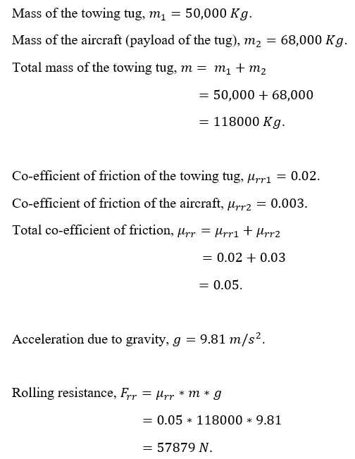
We consider the same parameters of the towing tug in order to calculate the energy required.
Mass of the towing tug = 50,000 Kg.
Mass of the aircraft = 68,000 Kg.
Total mass = 118,000 Kg.
Rolling resistance = 57879 N.
Co-efficient of drag of the towing tug = 0.3.
Co-efficient of drag of the aircraft = 0.15.
Speed of the towing tug = 10 Km/hr = 2.78 m/s.
Aerodynamic drag = 95.85 N.
Power required to tow the aircraft = 161.17 KW.
We also assume more parameter of the towing tug which are,
Time taken to tow the aircraft to the runway,t = 5 minutes = 0.083 hours.
Radius of the tire,r = 0.3 m.
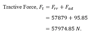
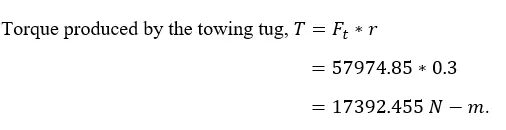
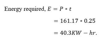
Therefore the energy required to tow the vehicle is 40.3 KWhr.
For this application a brushless DC motor is selected. The specifications of the motor is given below,
Output = 200 KW.
Speed = 3000 RPM.
Armature Voltage = 500 V DC.
Full Load Current = 340 A.
Field Voltage = 310 V DC.
Field Current = 7.74A.
In order to calculate the duty cycle we must know the input and ouput power.
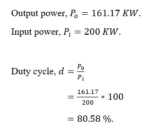
Therefore the duty cycle of the motor is 80.58%.
The simulink model of the EV power train is,
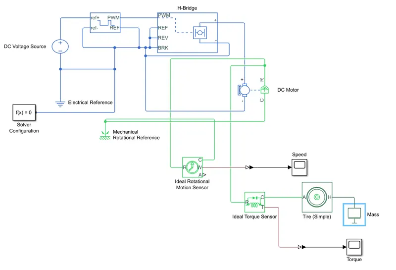
Explanation of the model,
- A DC voltage source block is used to provide the input voltage. It is then connected to the controlled PWM block to generate DC pulses.
- The PWM block is connected to the H-bridge block which acts as the switch for the pulses.
- The H-bridge block is connected to the DC motor block. The electrical section of the DC motor block is connected to an electrical reference and a solver configuration.
- The mechanical section of the DC motor is connected to a rotational sensor to obtain the speed and a torque sensor to obtain the torque.
- The torque sensor is connected to a tire block which is then connected to a translational mass block.
- The tire block and the mass block must be added or else the torque produced will be zero.
The simulation is run and the following plots are obtained.
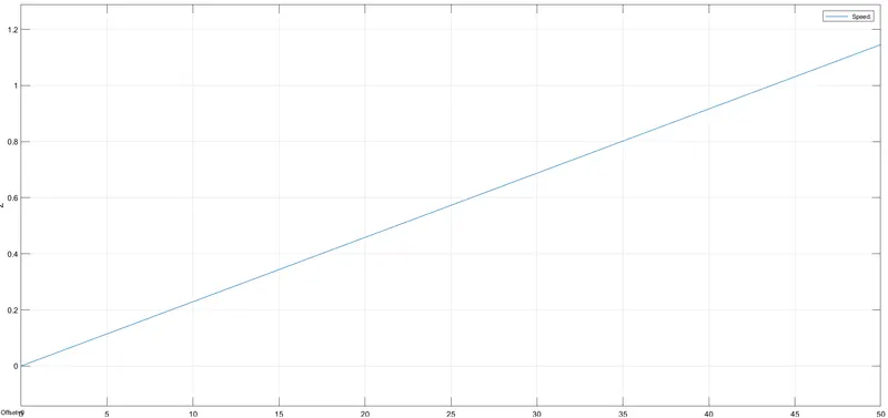
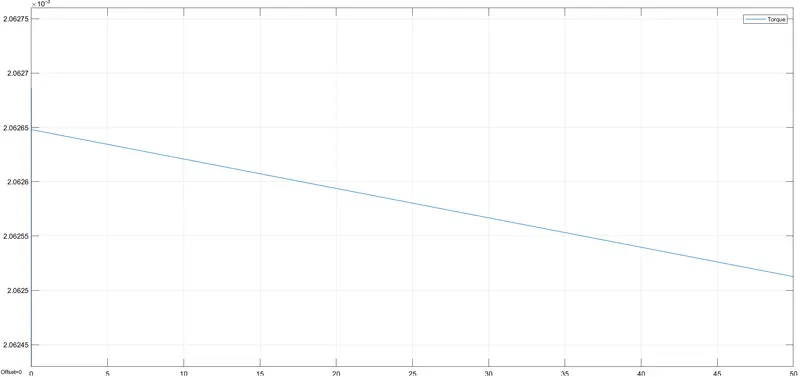
From the above two plots it can be seen that as the speed increases linearly the torque also decreases linearly.
Excel Sheet Data of the above model :-
CONCLUSION :-
- The total weight of various types of aircraft are listed.
- The difference betwen ground speed and air speed is explained.
- The reason for not using aircraft's engine power on the ground is explained.
- How pushback works on aircraft is explained.
- Take off power, rolling resistance, tire design, tire pressure and braking during landing are explained.
- The forces and power required to tow an aircraft are calculated.
- The Simulink model of an EV drivetrain to tow an aircraft was designed.