Powertrain for aircraft in runways
1. Search and list out the total weight of various types of aircraft.
The aircraft gross weight (also known as the all-up weight and abbreviated AUW) is the total aircraft weight at any moment during the flight or ground operation. An aircraft's gross weight will decrease during a flight due to fuel and oil consumption. An aircraft's gross weight may also vary during a flight due to payload dropping or in-flight refueling. At the moment of releasing its brakes, the gross weight of an aircraft is equal to its takeoff weight. During the flight, an aircraft's gross weight is referred to as the en-route weight or in-flight weight. The various types of terms related to weight are as follows.
1. Manufacturer's empty weight (MEW)
It is the weight of the aircraft "as-built" and includes the weight of the structure, power plant, furnishings, installations, systems, and other equipment that are considered an integral part of an aircraft.
2. Zero-Fuel weight (ZFW)
This is the total weight of the airplane and all its contents (including unusable fuel), but excluding the total weight of the usable fuel on board. Maximum zero fuel weight (MZFW) is the maximum weight allowed before usable fuel and other specified usable agents (engine injection fluid, and other consumable propulsion agents) are loaded.
3. Operating empty weight (OEW)
It is the basic weight of an aircraft including the crew, all fluids necessary for operation such as engine oil, engine coolant, water, unusable fuel, and all operator items and equipment required for flight but excluding usable fuel and the payload.
4. Payload
It is the carrying capacity of an aircraft. It includes cargo, people, extra fuel. In the case of a commercial airliner, it may refer only to revenue-generating cargo or paying passengers.
5. Maximum Takeoff Weight (MTOW)
This is the maximum weight at which the pilot of the aircraft is allowed to attempt to take off.
6. Regulated takeoff weight (RTOW)
Depending on different factors (e.g. flap setting, altitude, air temperature, length of runway), RTOW or maximum permissible takeoff weight varies for each takeoff. It can never be higher than MTOW.
7. Maximum landing weight (MLW)
This maximum weight at which an aircraft is permitted to land.
8. Maximum Ramp Weight (MRW)
It is the maximum weight authorized for maneuvering (taxiing or towing) an aircraft on the ground.
9. Aircraft Gross Weight (AGW)
It is the total aircraft weight at any moment during the flight or ground operation. This decreases during the flight due to fuel and oil consumption.
So based on MTOW and MLW, a list of different aircraft is tabulated as shown below.
| TYPE | MTOW | MLW |
| Airbus A380-800 | 5,75,000 | 394 |
| Boeing 747-8F | 4,47,700 | 346.091 |
| Boeing 747-8 | 4,43,613 | 306.175 |
| Boeing 747-400ER | 4,12,770 | 295.742 |
| Boeing 747-400 | 3,96,900 | 295.742 |
| Boeing 777F | 3,47,800 | 260.816 |
| Airbus A330-900 | 3,52,000 | 251.5 |
| Boeing 777-300ER | 3,51,800 | 251.29 |
| Boeing 777-200LR | 3,47,450 | 223.168 |
| Boeing 747-100 | 3,40,200 | 265.3 |
| Airbus A350-1000 | 3,08,000 | 233.5 |
| Boeing 777-300 | 2,99,370 | 237.683 |
| Boeing 777-200ER | 2,97,550 | 213 |
| Airbus A340-300 | 2,76,700 | 190 |
| Airbus A350-900 | 2,70,000 | 175 |
| Airbus A330-300 | 2,42,000 | 185 |
| Airbus A330-200 | 2,42,000 | 180 |
| Lockheed L-1011-500 | 2,31,300 | 166.92 |
| Boeing 787-8 | 2,28,000 | 172.365 |
| Lockheed L-1011-200 | 2,11,400 | |
| Ilyushin IL-86 | 2,08,000 | 175 |
| Boeing 767-400ER | 2,04,000 | 158.758 |
| Airbus A300-600R | 1,92,000 | 140 |
| Boeing 767-300ER | 1,87,000 | 136.08 |
| Concorde | 1,85,000 | 111.1 |
| Airbus A300-600 | 1,63,000 | 138 |
| Boeing 767-300 | 1,59,000 | 136.078 |
| Airbus A310-300 | 1,57,000 | 124 |
| Vickers VC10 | 1,52,000 | 151.9 |
| Boeing 707-320B | 1,51,000 | 97.5 |
| Boeing 707-320C | 1,51,000 | 112.1 |
| Douglas DC-8-61 | 1,47,000 | |
| Airbus A310-200 | 1,42,000 | 123 |
| Airbus A400M | 1,41,000 | 122 |
| Douglas DC-8-32 | 1,40,000 | |
| Douglas DC-8-51 | 1,25,000 | |
| Boeing 757-300 | 1,24,000 | 101.6 |
| Boeing 707-120B | 1,17,000 | 86.3 |
| Boeing 757-200 | 1,16,000 | 89.9 |
| Boeing 720B | 1,06,000 | 79.5 |
| Boeing 720 | 1,04,000 | 79.5 |
| Tupolev Tu-154M | 1,04,000 | 80 |
| Tupolev Tu-204SM | 1,04,000 | 87.5 |
| Convair 880 | 87,500 | |
| Boeing 737-900 | 85,000 | 66.36 |
| Boeing 737-900ER | 85,000 | 71.35 |
| Boeing 727-200 Advanced | 84,000 | 70.1 |
| Boeing 737-400 | 68,000 | 54.9 |
| de Havilland Comet 3 | 68,000 | |
| Boeing 737-600 | 66,000 | 54.66 |
| Airbus A220-300 | 65,000 | 57.61 |
| Airbus A319 | 64,000 | 62.5 |
| Boeing 737-300 | 63,000 | 51.7 |
| Boeing 737-500 | 60,000 | 49.9 |
| Airbus A220-100 | 59,000 | 50.8 |
| Airbus A318 | 59,000 | 57.5 |
| Boeing 717-200HGW | 55,000 | 47.174 |
| Douglas DC-7 | 55,000 | |
| de Havilland Comet 2 | 54,000 | |
| Boeing 717-200BGW | 50,000 | 46.265 |
| de Havilland Comet 1 | 50,000 |
2. Is there any difference between ground speed and airspeed?
There are two different types of speed when talking about airplanes – ground speed and airspeed. While ground speed is the airplane’s speed relative to the surface of the Earth, airspeed – at least true airspeed – is its speed relative to the air it is flying in.
Airspeed Vs Ground speed-
As mentioned above, true airspeed is simply the speed at which an aircraft is moving relative to the air it is flying in. As such, it’s also the speed at which the air is flowing around the aircraft’s wings. Ground speed, on the other hand, is the aircraft’s speed relative to the ground. One thing that should be noted here is that it’s horizontal rather than vertical speed – an aircraft climbing completely vertically would have a ground speed of zero. In other words, while airspeed is what determines whether there is enough airflow around an aircraft to make it fly, ground speed is what determines how fast an aircraft will get to its destination.
Wind's effect on ground speed-
The relationship between airspeed and ground speed is fairly simple. Ground speed is simply the sum of airspeed and wind speed. If the aircraft is flying in the same direction as the wind is blowing, the aircraft experiences tailwind, and its ground speed is higher than its airspeed. On the other hand, if the wind is blowing against the direction the aircraft is traveling in, the aircraft experiences headwind, and its ground speed is lower than its airspeed.
To give an actual example, imagine an aircraft that cruises at an airspeed of 500 miles per hour that has to cover a ground distance of 2,000 miles.
If there is no wind at all, then both the aircraft’s airspeed and ground speed would be the same 500 miles per hour, and the aircraft would reach its destination in four hours.
If there was a 100 miles per hour headwind – wind blowing against the aircraft’s direction of travel – the aircraft would still be traveling at an airspeed of 500 miles per hour. However, its ground speed would be just 400 miles per hour (100 miles per hour slower than its airspeed). And as such, it would take the aircraft five hours to reach its destinations.
Finally, if there was a 100 miles per hour tailwind – wind blowing in the same direction as the aircraft’s travel – the aircraft would still be traveling at an airspeed of 500 miles per hour, but its ground speed would be 100 miles faster. And, at 600 miles an hour, the aircraft would reach its destination in just three hours and twenty minutes.
3. Why is it not recommended to use aircraft engine power to move it on the ground at the Airport?
Aircraft are not always moved with tugs (the small vehicle you refer to). Much of the time, they operate under their own power.
Airliners are generally pushed back from the gate using a tug, as that's the simplest and most efficient method. They then taxi to the runway (and all the way up to the gate, after landing) using their own engines to provide thrust. This is true of both jets and propeller aircraft. This is called taxiing. For example, Boeing commercial airplanes are equipped with engines rated from 18,000 to nearly 100,000 lb of thrust. Such thrust levels provide for a safe takeoff, flight, and landing over a wide range of temperatures, altitudes, gross weights, and payload conditions. However, the exhaust wake from these engines can pose hazards in commercial airport environments. Operators and airport authorities must carefully consider these hazards and the resulting potential for injury to people and damage to or caused by baggage carts, service vehicles, airport infrastructure, and other airplanes.
Maintenance Activity
High engine thrust during maintenance activity can cause considerable damage to airplanes and other elements in the airport environment. An example of this problem occurred after an airplane arrived at its final destination with a log entry indicating the flight crew had experienced anomalous engine operation. The subsequent evaluation resulted in the replacement of an engine control component, followed by an engine test and trim run to verify proper engine operation. The airplane was positioned on an asphalt pad adjacent to a taxiway, with the paved surface extending from the wingtips aft to the empennage. During the high-power portion of the test run, a 20- by 20-ft (6.1- by 6.1-m) piece of the asphalt immediately aft of the engine detached and was lifted from the pad surface. This 4-in (10.2-cm)-thick piece of asphalt drifted up and into the core area of the left engine exhaust wake, where it shattered into numerous smaller pieces. The pieces were driven aft at substantial velocity, striking the aft fuselage and left outboard portion of the horizontal tail.
Foreign Object Damage
Foreign object damage (FOD) caused by high engine thrust can affect airport operations as it relates to
Airplane structure.
In an incident related to FOD caused by high engine thrust, Boeing was informed that a 737 had landed at a European airport and the flight crew had discovered significant damage during their walkaround inspection. Damaged areas included the right horizontal stabilizer leading edge and lower surface and elevator lower surface. Upon inspection, a piece of bricklike paving material was found embedded within the stabilizer structure.
Flight controls.
FOD can also affect flight control system component interaction and system displacement force, which are intimately related to properly functioning primary control surfaces. In most airplanes, the elevator is powered by independent hydraulic systems through power control units. Even subtle FOD to the external portions of the elevator can change the surface balance and alter the airflow characteristics in a way that may induce surface flutter. This dynamic and uncommanded movement of the surface can grow in both amplitude and frequency, causing additional damage. Portions of the surface may be destroyed by the violence of the induced motion. If this motion is great enough, it can be coupled into nearby airplane structures and cause collateral damage. In exceptional cases, control surface flutter could lead to loss of airplane control.
Equipment and personnel.
FOD also has the potential to affect the many aspects of ramp operations. These operations subject people, baggage carts, service vehicles, and airport infrastructure to injury and damage.
Due to the above-mentioned reasons, it is not recommended to use aircraft engine power to move it on the ground at the airport.
4. How an aircraft is pushed to the runway when it's ready to take off?
An aircraft is pushed to the runway when it's ready to take off using 2 methods, taxiing and towing.
Aircraft Towing-
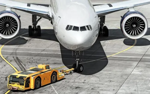
In the parking areas, where taxing the aircraft is not practical or is unsafe, such as moving aircraft in and out of maintenance hangars, or moving aircraft that are not under their own power or moving backward, then towing of aircraft is performed using the power of a specialized ground vehicle attached to or supporting the nose landing gear. The traditional method of allowing the ground vehicle to move an aircraft is to attach it to the aircraft nose landing gear utilizing a towbar. As the pilot cannot see what is behind the aircraft, steering is done by pushback tractor driver and depending on the aircraft type and airline procedure, a bypass pin may be temporarily installed into the nose gear to disconnect it from the aircraft's normal steering mechanism. Once the towing is completed, the towbar is disconnected and the aircraft can move forward under its own power.
Aircraft Taxiing-
Taxiing is the movement of an aircraft on the ground under its own power while on the surface. The aircraft always moves following the yellow lines, to avoid collision with the surrounding buildings, vehicles, or other aircraft. The taxiing motion has a speed limit, before making a turn the pilot reduces speed further to prevent the tire skids just like other vehicles. The reason for taxing is to reach the vehicle into the runway or from runway to terminal. Following the taxiway, the aircraft reaches the runway. Take-off is the phase of flight in which an aircraft goes through a transition from moving along the ground to flying in the air, usually starting line of the runway. Usually, the engines are run at full power during take-off. Following the taxi motion, the aircraft stops at the starting line of the runway. Before take-off, the engines particularly, piston engines are routinely run at high power to check for engine-related problems. This makes considerable noise. When the pilot releases the brakes, the aircraft starts accelerating rapidly until the necessary speed for take-off is achieved. The take-off speed required varies with air density, aircraft weight, and aircraft configuration. Air density is affected by factors such as field elevation and air temperature.
5. Learn about take-off power, tire design, rolling resistance, tire pressure, brake forces when landing.
1. Take-off power-
Take-off power is the phase of flight in which an aerospace vehicle leaves the ground and becomes airborne.
For the aircraft that take off horizontally, this usually involves starting with a transition from moving along the ground on a runway. The take-off speed requires varies with air density, aircraft gross weight, and aircraft configuration.
The power from the engine of the aircraft used to achieve the flight is called take-off power and for light aircraft usually, full power is required during take-off, large transport category may use reduced power for take-off, where less than full power is applied to prolong the engine life, reduce maintaining cost, and reduce noise emotions.
This term is also known as take-off thrust. Pilots use a great amount of thrust at take-off to decrease engine wear take-off. The performance is carefully calculated before each take-ff ensuring proper speed, power setting, and flaps are used for the weight of the take-off on the runway intended and at the proper temperature. When using this method to take-off, it is always possible to increase to full power if the situation requires.
2. Aircraft tire design-
When one considers the forces that aircraft tires endure, it seems amazing that engineers were ever able to develop these special products. Some tires are subjected to speeds as fast as a race car while at the same time supporting more weight than the largest land moving machines. They go through cyclic exposure to varying temperatures and pressures. These factors make aircraft tire design a critical process and tire maintenance an ever-important step in safe aircraft operation.
Designing aircraft tires is a very intense undertaking. Once an aircraft manufacturer goes to the tire manufacturer with the size and weight requirements, the tire manufacturer begins the process of designing a tire that meets the needs of the aircraft manufacturer as well as all regulatory requirements — including foreign regulations in many cases.
Engineers are challenged with designing tires with cool running, heat-resistant materials while simultaneously exceeding tire service requirements. Tire prototypes are put through rigorous tests that simulate cycles of landings, take-offs, and taxi operations. It is only after the tires pass all mandatory tests and meet the requirements of the aircraft manufacturer and airworthiness authorities that the tires are put into production. Two types of tires are used in aircraft applications — bias-ply tires and radial tires. Although both types of tires share some similarities in design, some differences need to be noted.
Bias-ply tire construction
A cutaway of a typical bias-ply tire is shown in the figure below. Bias-ply tires are popular choices for aircraft tires because of their durability and retreadability. The tire construction consists of the following components:
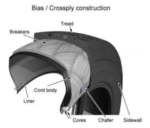
Tread: The tread is made of rubber mixed with other additives to obtain the desired level of toughness, durability, and resistance to wear. The tread pattern is designed to aircraft operational requirements, with the ribbed tread design used widely due to its good traction under varying runway conditions.
Sidewall: The sidewall is a protective layer of rubber that covers the outer casing ply. It extends from the tread edge to the bead area.
Tread Reinforcing Ply: One or more layers of fabric that strengthens and stabilizes the tread area for high-speed operation. It also serves as a reference for the buffing process when tires are retreaded.
Buff Line Cushion: The buff line cushion is made of rubber compound to enhance the adhesion between the tread reinforcing ply and the breakers or casing plies. It is of sufficient thickness to allow for the removal of the old tread when the tire is retreaded.
Breakers: Breakers are reinforcing plies of rubber-coated fabric placed under the buff line cushion to protect casing plies and strengthen and stabilize the tread area. They are considered an integral part of the casing construction.
Casing Plies: Alternate layers of rubber-coated fabric (running at opposite angles to one another) provide the strength of the tire.
Wire Beads: Hoops of high tensile strength steel wire that anchor the casing plies and provide a firm mounting surface on the wheel. The outer edge of the bead that fits against the wheel flange is called the bead heel. The inner bead edge is called the bead toe.
Apex Strip: A wedge of rubber affixed to the top of the bead bundle.
Flippers: Layers of rubberized fabric that help anchor the bead wires to the casing and improve the durability of the tire.
Ply Turnups: The casing plies are anchored by wrapping them around the wire beads, thus forming the ply turnups.
Chafer: A protective layer of rubber and/or fabric located between the casing plies and wheel to minimize chafing.
Liner: In tubeless tires, the liner is a layer of low permeability rubber that acts as a built-in tube and restricts gas from diffusing into the casing plies. In tube-type tires, a thinner liner is used to prevent tube chafing against the inside ply.
Radial-ply tire construction
A typical radial tire is illustrated in the figure below. With their rigid belt, they provide increased landings and reduced rolling resistance. They have fewer components in their construction and are lighter than similarly sized bias-ply tires. Components that differ from bias-ply construction as follows:
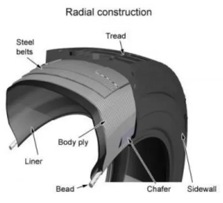
Overlay: A layer of reinforcing rubber-coated fabric placed on top of the belts to aid in high-speed operation.
Belt Plies: A composite structure that stiffens the tread area for increased landings. The belt plies increase the tire strength in the tread area.
Casing Plies: As in bias-ply tires, the casing plies are layers of rubber-coated fabric. However, unlike those in bias plies that run at opposite angles to one another, radial plies run radially from bead to bead.
Chippers: The chippers are layers of rubber-coated fabric applied at diagonal angles that improve the durability of the tire in the bead area.
3. Rolling resistance
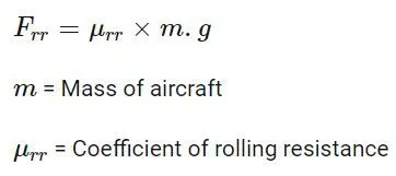
Rolling resistance is the force resisting the motion when a body rolls on a surface.
Rolling resistance can be seen in the aircraft when the aircraft takes-off from the runway and while landing at the runway with the help of their wheels.
It can be expressed as-
4. Tyre pressure -
An aircraft tire or tire is designed to withstand extremely heavy loads for short durations. The number of tires required for aircraft increases with the weight of the aircraft, as the weight of the airplane needs to be distributed more evenly. Aircraft tire tread patterns are designed to facilitate stability in high crosswind conditions, to channel water away to prevent hydroplaning, and for the braking effect.
Aircraft tires also include fusible plugs (which are assembled on the inside of the wheels), designed to melt at a certain temperature. Tires often overheat if maximum braking is applied during an aborted takeoff or an emergency landing. The fuses provide a safer failure mode that prevents tire explosions by deflating in a controlled manner, thus minimizing damage to aircraft and objects in the surrounding environment.
Each of the twelve Boeing 777-300ER main tires is inflated to 220 psi (15 bar; 1,500 kPa), weighs 120 kg (260 lb), has a diameter of 134 cm (53 in), and is changed every 300 cycles while the brakes are changed every 2000 cycles. Each tire is worth about $5,000. Aircraft tires generally operate at high pressures, up to 200 psi (14 bar; 1,400 kPa) for airliners, and even higher for business jets. The main landing gear on the Concorde was typically inflated to 232 psi (16.0 bar), whilst its tail bumper gear tires were as high as 294 psi (20.3 bar). The high pressure and weight load on the Concorde tires were a significant factor in the loss of Air France Flight 4950.
Tests of airliner aircraft tires have shown that they can sustain pressures of a maximum of 800 psi (55 bar; 5,500 kPa) before bursting. During the tests, the tires have to be filled with water, to prevent the test room from being blown apart by the energy that would be released by gas when the tire bursts. Aircraft tires are usually inflated with nitrogen to minimize expansion and contraction from extreme changes in ambient temperature and pressure experienced during flight. Dry nitrogen expands at the same rate as other dry atmospheric gases (normal air is about 80% nitrogen), but common compressed air sources may contain moisture, which increases the expansion rate with temperature.
The requirement that an inert gas, such as nitrogen, be used instead of air for inflation of tires on certain transport category airplanes was prompted by at least three cases in which the oxygen in air-filled tires had combined with volatile gases given off by a severely overheated tire and exploded upon reaching autoignition temperature. The use of inert gas for tire inflation eliminates the possibility of a tire explosion.
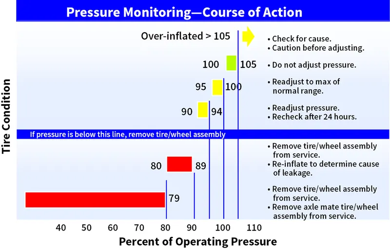
Improper tire pressure maintenance can have serious consequences for aircraft safety. One relatively easy way to help avoid those consequences is to check tire pressures regularly and service them as necessary. Following these three actions is a good way to make sure you get the most value out of your tires and contribute to the safe operation of your aircraft:
1. Perform daily pressure checks with a calibrated gauge.
2. Target the highest pressure recommended in the AMM or POH (105 percent of operating pressure).
3. Compensate for ambient temperature changes.
5. Brake Forces while landing -
Aircraft brakes stop moving the aircraft by converting its kinetic energy to heat energy using friction between rotating and stationary discs located in brake assemblies in the wheels. Brakes provide this critical stopping function during landings to enable airplanes to stop within the length of the runway.
Following braking devices are used to decelerate the aircraft -
1. Ground spoilers -
They are usually deployed automatically upon main-landing-gear-touchdown or activation of the thrust reverser.
Ground spoilers provide two aerodynamic effects-
- Increased aerodynamic drag contributes to aircraft deceleration.
- Lift-Dumping increases the load on the wheels and thus increases the wheel braking efficiency.
2. Wheel Brakes -
Braking action results from friction force between the tires and the runway surface. The friction force is affected by -
- Wheel speed (i.e, Free rolling, skidding, or rocked)
- Tire condition and pressure (i.e, friction surface)
- Runway condition (i.e, Runway friction coefficient)
- The load applied on the wheel
The braking force is equal to the load applied on the wheel multiplied by the runway friction coefficient. Anti-skid systems are designed to maintain the wheel-skidding factor near the point providing the maximum friction force, which is approximately 10% on a scale from 0% to 100% locked wheel.
Autobrake systems are designed to provide a selectable declaration rate, typically between three knots/sec to six knots/sec. When a low auto brake deceleration rate is selected and the brake pressure is applied usually after a specific time delay to give priority to the thrust reverser deceleration force at high airspeed.
3. Thrust reversers -
They provide a deceleration force that is independent of the runway condition. Thrust reverser efficiency is higher at high airspeed therefore, thrust reversers must be selected as early as possible after touchdown (following standard operating procedures).
Thrust reversers should be returned after reverse idle at low airspeed (to prevent engine stall or foreign object damage) and stowed at a taxi speed. Nevertheless, maximum engine speed can be maintained to a complete stop in an emergency.
6. With necessary assumptions, calculate the force and power required to push/pull an aircraft by a towing vehicle.
Let us assume
Weight of the aircraft (Boeing 747-8F) = 4,47,700 kg
To calculate the total rolling resistance force -
Rolling resistance coefficient of the aircraft (`murr`) = 0.004
Weight of the towing tractor = 50000 kg
Rolling resistance coefficient of the towing tractor (`murrt`) = 0.001
Rolling resistance force of the towing tractor = `murrt*m*g` = 0.001*50000*9.81 = 0.49kN/ 490.5 N
Rolling resistance force of the aircraft = `murr*m*g`= 0.004*447700*9.81 = 17.567kN/17567.75 N
Total Resistance force = Rolling resistance force of the aircraft + Rolling resistance force of the towing tractor = 0.49+17.56 = 18.05 kN.
To calculate the total air-drag force -
The equation is given by
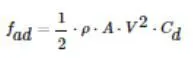
`rho`= Density of the air medium
A = frontal area of the vehicle which the airstrikes.
V = velocity with which the vehicle moves
Cd= Coefficient of drag which varies different shapes of the frontal area.
Let us now assume.
The velocity of aircraft while towing = 25 kmph (6.944 m/s)
The density of air medium = 1.225
The frontal area of the aircraft = 40 m^2.
The coefficient of the drag of the aircraft = 0.026
Air drag force = 0.5*`rho`*A*`V^2`*Cd = 0.5*1.225*40*6.944*0.026 = 30.7155 N = 0.0307 kN
We can ignore the air drag force experienced by the towing truck as it will be negligible compared to the air drag force experienced by the aircraft.
Therefore,
The total force that motor needs to overcome = Total rolling resistance force + Drag force acting on the aircraft
Total force = 18.05 + 0.0307 = 18.08 kN.
To calculate the power required by the motor-
The average speed of Push/Pull = 20 kmph = 5.5 m/s
Power required by the motor = Total force * velocity = 18.08*5.5 = 99.44 kW
To calculate the torque of the towing tractor -
Fte= The total tractive force (Rolling resistance + Drag force)
T=Torque output
r= Radius of tire
G=Gear ratio
For heavy-duty towing tractor, we assume -
G = 11 (for delivering high torque)
r = radius of tire = 25 inches = 0.635m
Therefore, T = Fte*r/G
The torque required to push or pull for the above-stated condition = 18.08*0.635/11 = 1.043 kNm
7. Design an electric powertrain with the type of motor, its power rating, and energy requirement to fulfill aircraft towing application. Estimate the duty cycle range to control the aircraft speed from zero to highest. Make all required assumptions. Prepare a table of assumed parameters. Draw a block diagram of the powertrain.
An aircraft pushback vehicle is required to move aircraft away from airport terminals. A powertrain is a system that covers all the drivetrain components which propel the vehicle on the road.
We consider an all-wheel-drive EV pushback vehicle that can achieve better wheel propulsion. This approach adds to the controllability of each wheel and decreasing the weight of the chassis. With proper control of each wheel, it is possible to achieve better acceleration, torque control, and regenerative braking. Implementation of Antilock Braking System (ABS), Collision Avoidance System (CAS), by-wire steering, and better overall dynamic stability control is much simpler using four in-wheel motors. The pushback vehicle must be able to generate a large towing tractive force, but also have a relatively high top speed to travel quickly between pushback operations (~30kmph unloaded).
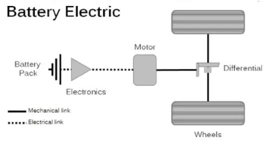
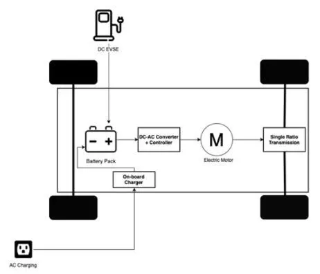
A simple block diagram of an electric powertrain is shown below.
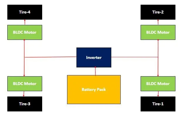
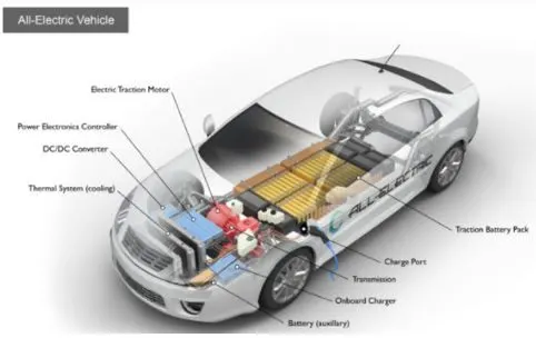
An EV powertrain has 60% fewer components than the powertrain of an ICE vehicle. These components are described below-
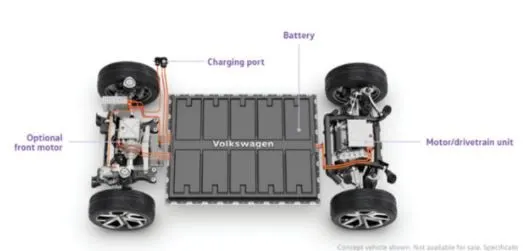
Battery pack - The battery pack is made up of multiple lithium-ion cells and stores the energy needed to run the vehicle. The battery pack provides the DC output.
DC-AC converter- The DC supplied by the battery pack is converted to AC and supplied to an electric motor. This power transfer is managed by a sophisticated motor control mechanism that controls the frequency and magnitude of the voltage supplied to the electric motor to manage the speed and acceleration as per the driver's instructions communicated via acceleration/brakes.
Electric motor - converts electrical energy to mechanical energy which is delivered to the wheels via single ratio transmission. Many EVs use motor generators that can perform regeneration as well.
On-Board charger - converts AC received through charge port to DC and controls the amount of current flowing into the battery pack.
Core components of EV powertrain -
Motor Design -
- Type of motor= BLDC motor
- Rated power = 20-25 kW
- Peak Power = 50kW
- Speed = 3200-5000 RPM
- Rated torque = 80 Nm
- Peak Torque = 160 Nm
- Efficiency = > 80%
Power Rating -
The rated power of the motor is 25kW and the peak power of the motor is double the rated power of the motor which is 50 kW.
The converter used in this is a DC-AC converter.
Assuming the input voltage = 349 V
Input current = 70 A
Now, Power input = Voltage * Current = 349*70 = 24.30 kW
Energy requirements -
The energy requirement for an EV is similar to the towing vehicle to push/pull the aircraft and is calculated based on time.
Let, Energy = Power*time taken by towing the vehicle to push/pull the aircraft
We know that power = 24.30 kW
Time taken by the towing vehicle to push/pull the aircraft = 15 min
So, energy = 24.30*15*60= 21870 kJ
Therefore, the power required by a single towing vehicle is 6.075 kW.
Duty Cycle-
The duty cycle of the electric powertrain is calculated as output power by the input power. By this, we get an efficiency of the duty cycle.
So, in our case,
Let, Output power = 19.94 kW
Input power = 24.30 kW
Therefore, the duty cycle = 19.94/24.30 = 0.82/82%
Therefore, the efficiency of the duty cycle we get for this electric powertrain is 0 to 0.82 or 0 to 82%