Powertrain for aircraft in runways
Question
- Search and list out the total weight of various types of aircrafts.
- Is there any difference between ground speed and air speed?
- Why is it not recommended to use aircraft engine power to move it on the ground at Airport?
- How an aircraft is pushed to runway when its ready to take off?
- Learn about take off power, tyre design, rolling resistance, tyre pressure, brake forces when landing.
- With necessary assumptions, calculate the force and power required to push / pull an aircraft by a towing vehicle.
7. Design an electric powertrain with type of motor, it’s power rating, and energy requirement to fulfill aircraft towing application. Estimate the duty cycle range to control the aircraft speed from zero to highest. Make all required assumptions. Prepare a table of assumed parameters. Draw a block diagram of powertrain.
Answers
#1
The different classification of aircrafts
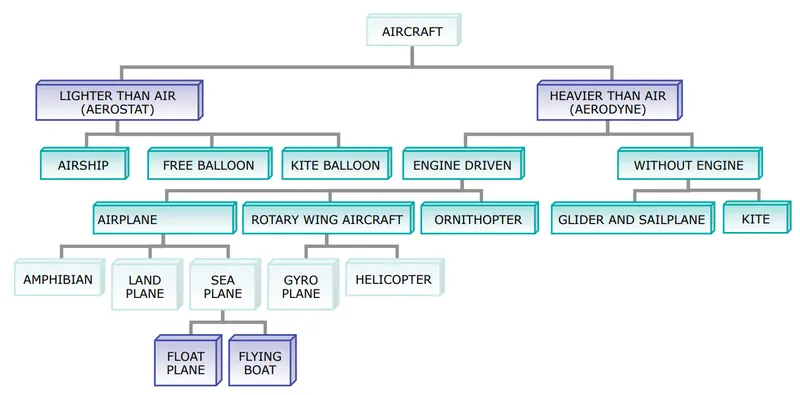
Aircrafts classified by their maximum takeoff weight and FAA category,
| Aircraft | Maximum Takeoff Weight [kg] | FAA Category |
| Antonov AN-225 | 640,000 | Super |
| Scaled Composites Model 351 Stratolaunch | 589,670 | Super |
| Airbus A380-800 | 575,000 | Super |
| Boeing 747-8F | 447,700 | Heavy |
| Boeing 747-8 | 443,613 | Heavy |
| Boeing 747-400ER | 412,770 | Heavy |
| Douglas DC-8-51 | 125,000 | Large |
| Boeing 757-300 | 124,000 | Large |
| Boeing 707-120B | 117,000 | Large |
| ATR 42-500 | 18,600 | Small |
| Saab 340 | 13,150 | Small |
| Embraer 120 Brasilia | 11,500 | Small |
#2
Airspeed is simply the speed at which an aircraft is moving relative to the air it is flying in. It is also the speed at which the air is flowing around the aircraft's wing. Airspeed is the difference between the ground speed and wind speed.
Ground speed, on the other hand, is the aircraft's speed relative to the ground. For a reference point picked on the ground, the aircraft moves relative to the reference point at the ground speed. The relationship is that the sum of airspeed and wind speed.
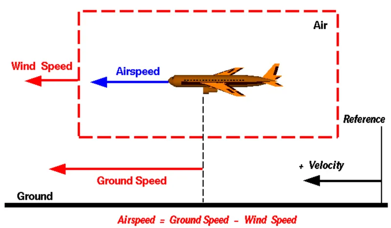
The importance of relative velocity explains why airplanes take off and land on different runways on different days. Airplanes always try to take off and land into the wind, as this requires a lower ground speed, which means the plane can take off or land in the shortest distance travelled along the ground.
#3
Commercial airplanes are equipped with engines rated from 18,000 to nearly 100,000 lb of thrust. Such immense thrust provides for safe take off, flight and landing over a wide range of temperatures, altitudes, gross weights and payload conditions. However, the exhaust wake from these engines can pose hazards in a commerical airport environment. The exhaust wake can exceed speeds of 600km/h immediately aft of the engine exhaust nozzle. This exhaust flow field extends aft in a rapidly expaning cone, this can blow away dust and even asphalt from the paved surface. The jet blasts from these engines might cause damage to the nearby equipments or other aircrafts or terminal buildings or even cause injuries and fatalities to human lives.
Exhaust wake from maximum takeoff thrust,
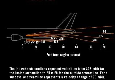
Takeoff thrust power hazard area,
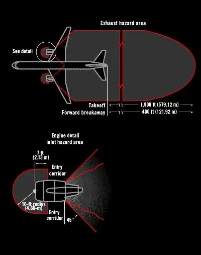
In the case of low mounted engines, there is a high probability that any gravel from the ground surface might get sucked into the engine and cause damage.
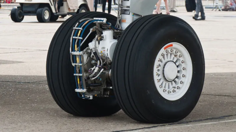
Another reason is the wastage of fuel. The movement of the airplane on the ground is called 'Taxiing'. Generally the jet engine is used as the main mode of propulsion for the ground movement but this results in huge loss of fuel which could have been used for flight. Also this unnecessary use of fuel causes further emissions. To solve this issue Electric taxiing systems (this system uses electric motors fitted inside the landing wheels of the airplanes, they are powered by the on-board Auxiliary Power Unit.) and Pushback trucks are used.
The benefits of using the electric taxiing system are
- more than 50% reduction in on-ground fuel burn
- 50-75% reduction in on-ground emissions `(NO_x, CO, HC, CO_2)`
- Improved safety of ground personnels
- Decreased engine maintenance by limiting Foreign Object Damage (FOD)
- Reduced brake use during taxi
- Reduced noise at the gate area
#4
As mention above, the movement of the airplane on the ground is called taxiing. This exludes the acceleration and deceleration run on the runway before takeoff and after landing respectively. The airplane can use its own engine power to move around on the ground but there are possibilies for various hazards. There it is prefered that taxiing is either done by using the Electric Taxiing System on the airplane or by using a Pushback truck.
Landing gear of an airplane with an Electric Taxiing System - the electric motor can be seen here,
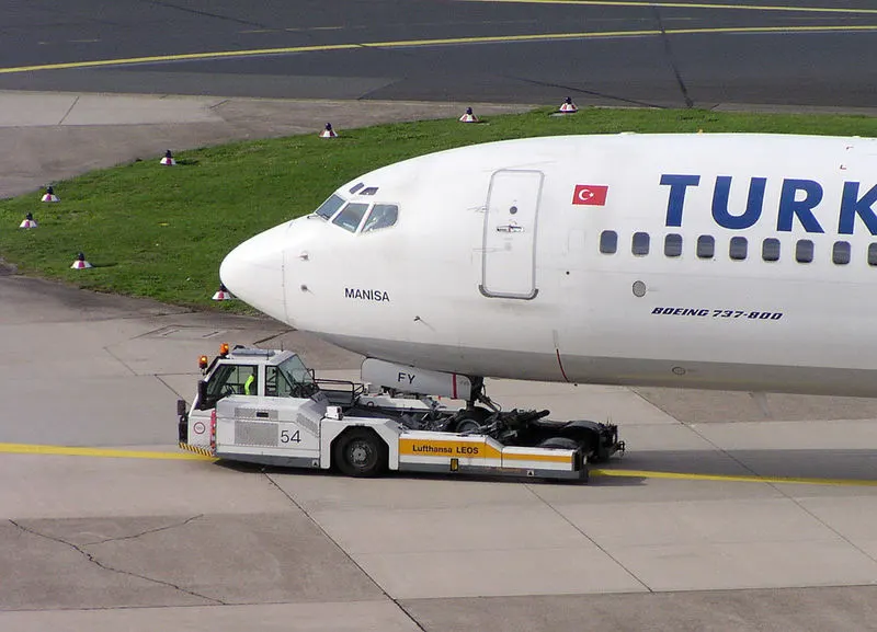
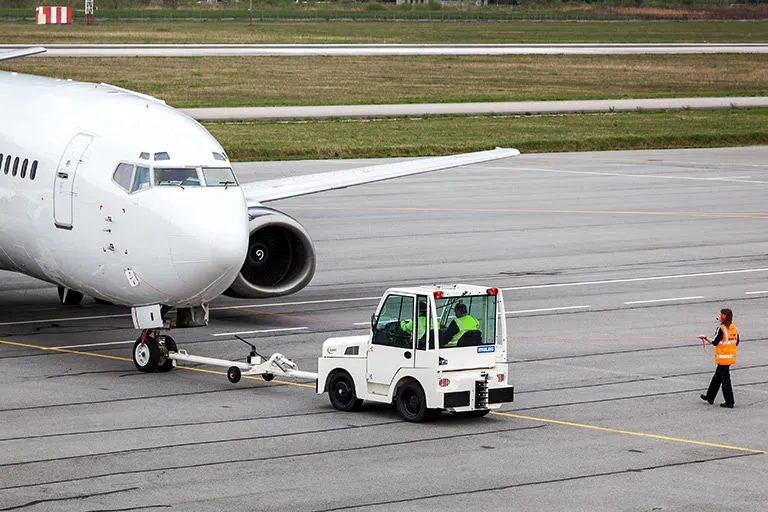
Pushback truck is specialized ground vehicles that have low profile design such that the are able to fit under the airplane nose, and uses a link to attach or support the nose landing gear. And the airplane can be pushed or pulled away from the airport gate to the runway. Most of the steering will be done by the driver in the pushback truck.
Images of airplanes being towed by Pushback trucks,
#5
TakeOff
Most takeoffs use derated thrust to save engine wear. For each takeoff the performance is carefully calculated, ensuring that the proper speeds, power setting and flaps are used for the weight of the takeoff on the runway intended. Usually this is below the maximum available thrust level and is known as derated thrust takeoff, such takeoffs are normal and frequently used, it is also possible to increase to full power if the situation requires. After all the captain makes the final decision.
The takeoff speed varies with air density, airplane weight, flap configuration.
Tyre Design
An aircraft tyre is designed to withstand extremely heavy loads for short durations unlike automobile tyres it doesn't have to carry load for long period of continous operations. The aircraft tyres have to absorb high impact loads of landing and be able to operate at very high speeds.
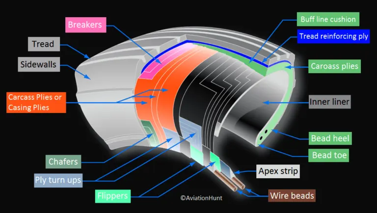
- The tyre bead is an important part of an aircraft tyre. It anchors the tire carcass and provides a dimensioned, firm mounting surface for the tyre on the wheel rim. Tyre beads are strong, they are made from high strength carbon steel wire bundles encased in rubber. Depending upon the load the tyre is designed to handle 1-3 bundles of beads can be found on each side of the tyre. The beads transfer the impact loads and deflection forces to the wheel rim.
- An apex strip is additional rubber formed around the bead to give a contour for anchoring the ply turnups. Chafer strips made of fabric or rubber are laid over the outer carcass piles, after the piles are wrapped around the beads. The chafers help reduce effect of wear and chafing between the wheel rim and the tyre bead during dynamic operations.
- Carcass piles, or casing piles as they are sometimes called are used to form the tire. Each ply consists of fabric, usually nylon, sandwiched between 2 layers of rubber. The piles are applied in layers to give the tyre strength and form the carcass body of the tyre. The angle of the fibre in the ply is manipulated to create a bias tyre or radial tyre as desired.
- The tread is the crown area of the tyre designed to come in contact with the ground. It is a rubber compound formulated to resist wear, abrasion, cutting, cracking and heat build-up. The tread is formed with circumferential grooves that create tyre ribs. The grooves provide cooling and help channel water from under the tyre in wet conditions to increase adhesion to the ground surface. The tread is designed to stabilize the aircraft on the operating surface and wears with use.
- The sidewall of an aircraft tyre is a layer of rubber designed to protect the carcass piles. The information about the tyre is contained on the sidewall. It may contain compunds to resist the negative effects of ozone on the tyre. The sidewall imparts little strength to the core body and its main function is protection.
Tyre Pressure
Aircraft tyres generally operate at high pressures, upto 200 psi (14 bar) for airliners and even higher for business jets. For example the Boeing 777-300ER main tyres are inflated to 220 psi (15 bar). The tyres are usually inflated with nitrogen to minimize expansion and contraction from extreme changes in ambient temperature and pressure experienced during operation.
Rolling Resistance
Rolling resistance or rolling friction is the force resisting the motion of a body when it rolls on a surface. It is mainly caused by non-elastic effects, that is, not all the energy needed for deformation of the wheel, is recovered when the pressure is removed. Two forms of this are hysteresis losses and permanent deformation of the object or the surface.
Rolling resistance can be expressed by the following equation,
`F_(rr) = mumg`
`F` - the rolling resistance force
`mu` - coefficient of rolling resistance
`m` - mass of the object
`g` - acceleration due to gravity
Brake Force
Braking force on an aircraft is provided by three systems - Aircraft disc brakes, Thrust reversers and Air brakes.
The disc brakes in the landing gear are operated hydraulicallyt or electrically (uses electric acctuators to save weight).
Thrust reversal is a temporary diversion of an aircraft engine's thrust for it to act against the forward travel of the aircraft, providing deceleration. These systems help slow down just after touch-down, reducing wear on the mechanical brakes and enablong shorter landing distances
Air brakes are a type of flight control surface used on an aircraft to increase the drag. Air brakes differ from spoilers in that air brakes are designed to increase drag while making little change to lift, whereas spoilers reduce the lift-to-drag ratio and require a higher angle of attack to maintain lift thereby resulting in a higher stall speed.
Aircraft brakes are designed considering the worst case scenario of rejected takeoff (RTO) at maximum rolling speed. Above this speed, a takeoff cannot be safely aborted without serious risk of the aircraft failing to stop before the end of the runway.
For example, Airbus A320 is one of the most popular aircraft. It has a maximum takeoff weight of 93000 kg and a takeoff speed around 275 kmph. Lets do an estimation for the maximum energy the brakes of the A320 need to dissipate during an RTO.
Kinetic energy of A320 during RTO, `KE = 1/2mv^2`
`KE = 0.5xx93000xx76.38^2 = 2.712xx10^8 J approx 75.35KWh`
To dissipate this much energy within the length of the runway the aircraft need to have disc brakes on most of its wheels, if not all. The A320 uses carbon composite brakes.
#6
The towing vehicle will experience two kinds of forces acting on it when required to push or pull an aircraft - Rolling resistance force, Aerodynamic drag and Gradient force.
Rolling resistance is the force resisting the motion when a body rolls on a surface.
Rolling resistance is given by, `F_(rr) = mumg`
where, `mu` is the coefficient of rolling resistance, `m` is the mass and `g` is acceleration due to gravity.
For airplane assume that, `mu = 0.017, m = 65000 kg`
`F_(airplan e) = 0.017xx65000xx9.81 = 10840.05 N`
For towing vehicle assume that, `mu = 0.012, m = 3500 kg`
`F_(pushback) = 0.012*3500*9.81 = 412.02 N`
Total rolling resistance, `F_T = F_(airplan e) + F_(pushback)`
`F_(rr) = 10840.05 + 412.02 = 11252.07 N`
Let us assume that the ground surface is an absolute flat and the airplane is being towed at a very low speed. Therefore we can neglect the gradient force.
Let the towing speed be `v = 20 (km)/h = 5.55 m/s`
Density of air, `rho = 1.225 (kg)/m^3`
Drag coefficient of aircraft, `C_d = 0.018`
Frontal Area of aircraft, `A = 16 m^2`
Force due to aerodynamic drag, `F_(ad) = (rhoAV^2C_d)/2`
`F_(ad) = 5.43 N`
Total Force acting,
`F_T = F_(rr) + F_(ad)`
`F_T = 11252.07 + 5.43 = 11257.5 N = 11.26 kN`
Power required by the tow vehicle to pull the aircraft,
`P = F_Txxv`
`P = 11.26xx5.55 = 62.5 kW`
The towing vehicle will require a power of 62.5 kW to pull the above aircraft at a speed of 20 kmph.
#7
Here, all the assumptions in the previous question is used.
Assumptions is as follows,
| Weight of aircraft | 65000 kg |
| Weight of towing vehicle | 3500 kg |
| Coefficient of rolling resistance of aircraft | 0.017 |
| Coefficient of rolling resistance of towing vehicle | 0.012 |
| Density of air | 1.225 kg/m^3 |
| Velocity of aircraft while towing | 20 km/h = 5.55 m/s |
| Drag coefficient of aircraft | 0.018 |
| Frontal Area | 16 m^2 |
| Wheel radius of towing vehicle | 0.52m |
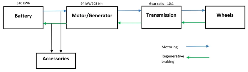
| Gear ratio of transmission | 10:1 |
| Acceleration due to gravity | 9.81 m/s^2 |
Let the tyre radius of the towing vehicle be, `r_w = 0.52 m`
Torque needed at the wheels of the towing vehicle = Total force x Radius of the wheel
`T_w = F_Txxr_w`
`T_w = 11257.5xx0.52 = 5853.9 Nm`
Let the gear ratio between the motor and the wheel be, `G = 10:1`
For every 10 rotation of the motor the wheel rotates once.
Motor torque required, `T_m = T_w/G = 585.39 Nm`
Assuming a transmission losses of 10% and motor losses of 10%, the motor torque required is,
`T_m = 585.39 + 585.39xx(0.1+0.1)`
`T_m = 703 Nm`
Power needed to pull the aircraft, `P = 62.5 kW`
Motor efficiency is 95% and it is required to run at 70% full capacity for safety reasons.
Motor power required, `P_m = P/(0.95xx0.7)`
`P_m = 62.5/(0.95xx0.7) = 94 kW or 126 HP`
Motor Specifications Required
Torque = 703 Nm / 520 ft lbs
Power = 94 kW / 126 HP (peak)
Required power from motor is 62.5 kW and rated motor peak power is 94 kW
Duty cycle, `D = 62.5/94 = 0.664 approx 0.67`
The duty cycle range is from 0 to 0.67.
Let us assume that the average time for taxiing for an aircraft is 15 minutes. Calculation for the energy required to move the aircraft is as follows,
Energy = Power x Time
`E = Pxx15xx60`
`E=62.5xx15xx60`
`E = 56250 kJ = 15.625 kWh`
Therefore, the energy required to operate the towing vehicle to pull the aircraft once is 15.625 kWh.
Also the tow vehicle will require to move from its station to the aircraft and then from the runway and back to the station. Assuming that these movements will consume around 1 kWh energy. Apart from this, there will be power conversion losses. Let us assume that the power loss and the power consumed by other accessories for one trip is 0.375 kWh.
Total power consumed by the towing vehicle for one trip,
`E_1 = 15.625 + 1 + 0.375 = 17 kWh`
Assuming that on a full charge of battery the tow vehicle can perform 20 operations
Therefore, the required battery capacity = 17 kWh x 20 = 340 kWh
Electric Powertrain Specifications
Motor specifications -> Power - 94 kW, Torque - 703 Nm
Power Inverter specification -> Duty cycle range - 0 to 0.67%. Handling capacity - 94kW
Battery Capacity -> 340 kWh
Block Diagram showing the flow of power in the electric powertrain of the towing vehicle,